Virtualization product documentation
OpenShift Virtualization installation, usage, and release notes
Abstract
Chapter 1. About
1.1. About OpenShift Virtualization
OpenShift Virtualization provides a comprehensive virtualization solution that allows you to run and manage virtual machine workloads alongside container workloads in your OpenShift Container Platform cluster.
1.1.1. What you can do with OpenShift Virtualization
OpenShift Virtualization provides the scalable, enterprise-grade virtualization functionality in Red Hat OpenShift. You can use it to manage virtual machines (VMs) exclusively or alongside container workloads.
If you have a Red Hat OpenShift Virtualization Engine subscription, you can run unlimited VMs on subscribed hosts, but you cannot run application instances in containers. For more information, see the subscription guide section about "Red Hat OpenShift Virtualization Engine and related products".
OpenShift Virtualization adds new objects into your OpenShift Container Platform cluster by using Kubernetes custom resources to enable virtualization tasks. These tasks include:
- Creating and managing Linux and Windows VMs
- Running pod and VM workloads alongside each other in a cluster
- Connecting to VMs through a variety of consoles and CLI tools
- Importing and cloning existing VMs
- Managing network interface controllers and storage disks attached to VMs
- Live migrating VMs between nodes
You can manage your cluster and virtualization resources by using the Virtualization perspective of the OpenShift Container Platform web console, and by using the OpenShift CLI (oc).
For supported and unsupported OVN-Kubernetes network plug-in use cases, see "OVN-Kubernetes purpose".
OpenShift Virtualization is designed and tested to work well with Red Hat OpenShift Data Foundation features.
When you deploy OpenShift Virtualization with OpenShift Data Foundation, you must create a dedicated storage class for Windows virtual machine disks. See "Optimizing ODF PersistentVolumes for Windows VMs" for details.
You can use OpenShift Virtualization with OVN-Kubernetes or one of the other certified network plug-ins listed in "Certified OpenShift CNI Plug-ins".
You can check your OpenShift Virtualization cluster for compliance issues by installing the Compliance Operator and running a scan with the ocp4-moderate and ocp4-moderate-node profiles. The Compliance Operator uses OpenSCAP, a NIST-certified tool, to scan and enforce security policies.
For information about partnering with Independent Software Vendors (ISVs) and Services partners for specialized storage, networking, backup, and additional functionality, see the Red Hat Ecosystem Catalog.
1.1.2. Comparing OpenShift Virtualization to VMware vSphere
If you are familiar with VMware vSphere, the following table lists OpenShift Virtualization components that you can use to accomplish similar tasks.
However, because OpenShift Virtualization is conceptually different from vSphere, and much of its functionality comes from the underlying OpenShift Container Platform, OpenShift Virtualization does not have direct alternatives for all vSphere concepts or components.
Table 1.1. Mapping of vSphere concepts to their closest OpenShift Virtualization counterparts
| vSphere concept | OpenShift Virtualization | Explanation |
|---|---|---|
| Datastore | Persistent volume (PV) Persistent volume claim (PVC) |
Stores VM disks. A PV represents existing storage and is attached to a VM through a PVC. When created with the |
| Dynamic Resource Scheduling (DRS) | Pod eviction policy Descheduler | Provides active resource balancing. A combination of pod eviction policies and a descheduler allows VMs to be live migrated to more appropriate nodes to keep node resource utilization manageable. |
| NSX | Multus OVN-Kubernetes Third-party container network interface (CNI) plug-ins | Provides an overlay network configuration. There is no direct equivalent for NSX in OpenShift Virtualization, but you can use the OVN-Kubernetes network provider or install certified third-party CNI plug-ins. |
| Storage Policy Based Management (SPBM) | Storage class | Provides policy-based storage selection. Storage classes represent various storage types and describe storage capabilities, such as quality of service, backup policy, reclaim policy, and whether volume expansion is allowed. A PVC can request a specific storage class to satisfy application requirements. |
| vCenter vRealize Operations | OpenShift Metrics and Monitoring | Provides host and VM metrics. You can view metrics and monitor the overall health of the cluster and VMs by using the OpenShift Container Platform web console. |
| vMotion | Live migration |
Moves a running VM to another node without interruption. For live migration to be available, the PVC attached to the VM must have the |
| vSwitch DvSwitch | NMState Operator Multus | Provides a physical network configuration. You can use the NMState Operator to apply state-driven network configuration and manage various network interface types, including Linux bridges and network bonds. With Multus, you can attach multiple network interfaces and connect VMs to external networks. |
1.1.3. Supported cluster versions for OpenShift Virtualization
OpenShift Virtualization 4.21 is supported for use on OpenShift Container Platform 4.21 clusters. To use the latest z-stream release of OpenShift Virtualization, you must first upgrade to the latest version of OpenShift Container Platform. The latest stable release of OpenShift Virtualization 4.21 is 4.21.8.
1.1.4. About volume and access modes for virtual machine disks
If you use the storage API with known storage providers, the volume and access modes are selected automatically. However, if you use a storage class that does not have a storage profile, you must configure the volume and access mode.
For a list of known storage providers for OpenShift Virtualization, see the Red Hat Ecosystem Catalog.
For best results, use the ReadWriteMany (RWX) access mode and the Block volume mode. This is important for the following reasons:
-
ReadWriteMany(RWX) access mode is required for live migration. The
Blockvolume mode performs significantly better than theFilesystemvolume mode. This is because theFilesystemvolume mode uses more storage layers, including a file system layer and a disk image file. These layers are not necessary for VM disk storage.For example, if you use Red Hat OpenShift Data Foundation, Ceph RBD volumes are preferable to CephFS volumes.
You cannot live migrate virtual machines with the following configurations:
-
Storage volume with
ReadWriteOnce(RWO) access mode - Passthrough features such as GPUs
Set the evictionStrategy field to None for these virtual machines. The None strategy powers down VMs during node reboots.
1.1.5. Single-node OpenShift differences
You can install OpenShift Virtualization on single-node OpenShift.
However, you should be aware that Single-node OpenShift does not support the following features:
- High availability
- Pod disruption
- Live migration
- Virtual machines or templates that have an eviction strategy configured
1.1.6. Additional resources
- This content is not included.Red Hat OpenShift Virtualization Engine and related products
- OVN-Kubernetes
- Optimizing ODF PersistentVolumes for Windows VMs
- Compliance Operator
- Supported compliance profiles
- OpenShift Virtualization supported limits
- OVN-Kubernetes purpose
- Glossary of common terms for OpenShift Container Platform storage
- About single-node OpenShift
- This content is not included.Using the OpenShift Assisted Installer Service to Deploy an OpenShift Cluster on Bare Metal and vSphere
- Certified OpenShift CNI Plug-ins
- Content from www.nist.gov is not included.NIST-certified tool
- Content from red.ht is not included.Red Hat Ecosystem Catalog
- Pod disruption budgets
- About live migration
- Configure eviction and run strategies
- Tuning & Scaling Guide in the Red Hat Knowledgebase
1.2. Supported limits
You can refer to tested object maximums when planning your OpenShift Container Platform environment for OpenShift Virtualization. However, approaching the maximum values can reduce performance and increase latency. Ensure that you plan for your specific use case and consider all factors that can impact cluster scaling.
For more information about cluster configuration and options that impact performance, see the "OpenShift Virtualization - Tuning & Scaling Guide" in the Red Hat Knowledgebase.
1.2.1. Tested maximums for OpenShift Virtualization
The following limits apply to a large-scale OpenShift Virtualization 4.x environment. They are based on a single cluster of the largest possible size. When you plan an environment, remember that multiple smaller clusters might be the best option for your use case.
1.2.1.1. Virtual machine maximums
The following maximums apply to virtual machines (VMs) running on OpenShift Virtualization. These values are subject to the limits specified in Virtualization limits for Red Hat Enterprise Linux with KVM.
| Objective (per VM) | Tested limit | Theoretical limit |
|---|---|---|
| Virtual CPUs | 216 vCPUs | 255 vCPUs |
| Memory | 6 TB | 16 TB |
| Single disk size | 100 TB | 100 TB |
| Hot-pluggable disks | 255 disks | N/A |
Each VM must have at least 512 MB of memory. The fstype in the guest operating system (OS) must support the maximum limits. Do not use preallocation in data volumes that are larger than 99 TB.
1.2.1.2. Host maximums
The following maximums apply to the OpenShift Container Platform hosts used for OpenShift Virtualization.
| Objective (per host) | Tested limit | Theoretical limit |
|---|---|---|
| Logical CPU cores or threads | Same as Red Hat Enterprise Linux (RHEL) | N/A |
| RAM | Same as RHEL | N/A |
| Simultaneous live migrations | Defaults to 2 outbound migrations per node, and 5 concurrent migrations per cluster | Depends on NIC bandwidth |
| Live migration bandwidth | No default limit | Depends on NIC bandwidth |
1.2.1.3. Cluster maximums
The following maximums apply to objects defined in OpenShift Virtualization.
| Objective (per cluster) | Tested limit | Theoretical limit |
|---|---|---|
| Number of attached PVs per node | N/A | CSI storage provider dependent |
| Maximum PV size | N/A | CSI storage provider dependent |
| Hosts | 500 hosts (100 or fewer recommended) [1] | Same as OpenShift Container Platform |
| Defined VMs | 10,000 VMs [2] | Same as OpenShift Container Platform |
If you use more than 100 nodes, consider using Red Hat Advanced Cluster Management (RHACM) to manage multiple clusters instead of scaling out a single control plane. Larger clusters add complexity, require longer updates, and depending on node size and total object density, they can increase control plane stress.
Using multiple clusters can be beneficial in areas like per-cluster isolation and high availability.
The maximum number of VMs per node depends on the host hardware and resource capacity. It is also limited by the following parameters:
-
Settings that limit the number of pods that can be scheduled to a node. For example:
maxPods. -
The default number of KVM devices. For example:
devices.kubevirt.io/kvm: 1k.
-
Settings that limit the number of pods that can be scheduled to a node. For example:
1.2.2. Additional resources
1.3. Security policies
OpenShift Virtualization provides built-in security features and authorization policies to protect virtual machine workloads and ensure secure cluster operations across your environment.
Key points
-
OpenShift Virtualization adheres to the
restrictedKubernetes pod security standards profile, which aims to enforce the current best practices for pod security. - Virtual machine (VM) workloads run as unprivileged pods.
-
Security context constraints (SCCs) are defined for the
kubevirt-controllerservice account. For more information about SSCs, see "Additional resources". - TLS certificates for OpenShift Virtualization components are renewed and rotated automatically.
1.3.1. About workload security
By default, virtual machine (VM) workloads do not run with root privileges in OpenShift Virtualization, and there are no supported OpenShift Virtualization features that require root privileges.
For each VM, a virt-launcher pod runs an instance of libvirt in session mode to manage the VM process. In session mode, the libvirt daemon runs as a non-root user account and only permits connections from clients that are running under the same user identifier (UID). Therefore, VMs run as unprivileged pods, adhering to the security principle of least privilege.
1.3.2. TLS certificates
TLS certificates for OpenShift Virtualization components are renewed and rotated automatically. You are not required to refresh them manually.
1.3.2.1. Automatic renewal schedules
TLS certificates are automatically deleted and replaced according to the following schedule:
- KubeVirt certificates are renewed daily.
- Containerized Data Importer controller (CDI) certificates are renewed every 15 days.
- MAC pool certificates are renewed every year. Automatic TLS certificate rotation does not disrupt any operations. For example, the following operations continue to function without any disruption:
- Migrations
- Image uploads
- VNC and console connections
1.3.3. Authorization
OpenShift Virtualization uses role-based access control (RBAC) to define permissions for human users and service accounts. The permissions defined for service accounts control the actions that OpenShift Virtualization components can perform.
You can also use RBAC roles to manage user access to virtualization features. For example, an administrator can create an RBAC role that provides the permissions required to launch a virtual machine. The administrator can then restrict access by binding the role to specific users.
1.3.3.1. Default cluster roles for OpenShift Virtualization
By using cluster role aggregation, OpenShift Virtualization extends the default OpenShift Container Platform cluster roles to include permissions for accessing virtualization objects. Roles unique to OpenShift Virtualization are not aggregated with OpenShift Container Platform roles.
Table 1.2. OpenShift Virtualization cluster roles
| Default cluster role | OpenShift Virtualization cluster role | OpenShift Virtualization cluster role description |
|---|---|---|
|
|
| A user that can view all OpenShift Virtualization resources in the cluster but cannot create, delete, modify, or access them. For example, the user can see that a virtual machine (VM) is running but cannot shut it down or gain access to its console. |
|
|
| A user that can modify all OpenShift Virtualization resources in the cluster. For example, the user can create VMs, access VM consoles, and delete VMs. |
|
|
|
A user that has full permissions to all OpenShift Virtualization resources, including the ability to delete collections of resources. The user can also view and modify the OpenShift Virtualization runtime configuration, which is located in the |
|
|
|
A user that can create, delete, and update VM live migration requests, which are represented by namespaced |
1.3.3.2. RBAC roles for storage features in OpenShift Virtualization
The following permissions are granted to the Containerized Data Importer (CDI), including the cdi-operator and cdi-controller service accounts.
1.3.3.2.1. Cluster-wide RBAC roles
Table 1.3. Aggregated cluster roles for the cdi.kubevirt.io API group
| CDI cluster role | Resources | Verbs |
|---|---|---|
|
|
|
|
|
|
| |
|
|
|
|
|
|
| |
|
|
|
|
|
|
| |
|
|
|
|
Table 1.4. Cluster-wide roles for the cdi-operator service account
| API group | Resources | Verbs |
|---|---|---|
|
|
|
|
|
|
|
|
|
|
|
|
|
|
|
|
|
|
|
|
|
|
|
|
|
|
Allow list: |
|
|
|
Allow list: |
|
|
|
|
|
Table 1.5. Cluster-wide roles for the cdi-controller service account
| API group | Resources | Verbs |
|---|---|---|
|
|
|
|
|
|
|
|
|
|
|
|
|
|
|
|
|
|
|
|
|
|
|
|
|
|
|
|
|
|
|
|
|
|
|
|
|
|
|
|
|
|
|
|
|
|
|
|
|
|
|
|
|
|
|
|
|
|
|
|
|
|
|
|
1.3.3.2.2. Namespaced RBAC roles
Table 1.6. Namespaced roles for the cdi-operator service account
| API group | Resources | Verbs |
|---|---|---|
|
|
|
|
|
|
|
|
|
|
|
|
|
|
|
|
|
|
|
|
|
|
|
|
|
|
|
|
Table 1.7. Namespaced roles for the cdi-controller service account
| API group | Resources | Verbs |
|---|---|---|
|
|
|
|
|
|
|
|
|
|
|
|
|
|
|
|
|
|
|
|
|
|
|
|
|
|
|
|
1.3.3.3. Additional SCCs and permissions for the kubevirt-controller service account
Security context constraints (SCCs) control permissions for pods. These permissions include actions that a pod, a collection of containers, can perform and what resources it can access. You can use SCCs to define a set of conditions that a pod must run with to be accepted into the system.
The virt-controller is a cluster controller that creates the virt-launcher pods for virtual machines in the cluster.
By default, virt-launcher pods run with the default service account in the namespace. If your compliance controls require a unique service account, assign one to the VM. The setting applies to the VirtualMachineInstance object and the virt-launcher pod.
The kubevirt-controller service account is granted additional SCCs and Linux capabilities so that it can create virt-launcher pods with the appropriate permissions. These extended permissions allow virtual machines to use OpenShift Virtualization features that are beyond the scope of typical pods.
The kubevirt-controller service account is granted the following SCCs:
scc.AllowHostDirVolumePlugin = true- This allows virtual machines to use the hostpath volume plugin.
scc.AllowPrivilegedContainer = false-
This ensures the
virt-launcherpod is not run as a privileged container. scc.AllowedCapabilities = []corev1.Capability{"SYS_NICE", "NET_BIND_SERVICE"}-
SYS_NICEallows setting the CPU affinity. -
NET_BIND_SERVICEallows DHCP and Slirp operations.
-
1.3.3.3.1. Viewing the SCC and RBAC definitions for the kubevirt-controller
You can view the SecurityContextConstraints definition for the kubevirt-controller by using the oc tool:
$ oc get scc kubevirt-controller -o yaml
You can view the RBAC definition for the kubevirt-controller clusterrole by using the oc tool:
$ oc get clusterrole kubevirt-controller -o yaml
1.3.4. Additional resources
- Content from kubernetes.io is not included.Pod Security Standards
- About Security context constraints
- Using RBAC to define and apply permissions
- Managing security context constraints
- Creating a cluster role
- Cluster role binding commands
- Enabling user permissions to clone data volumes across namespaces
1.4. OpenShift Virtualization Architecture
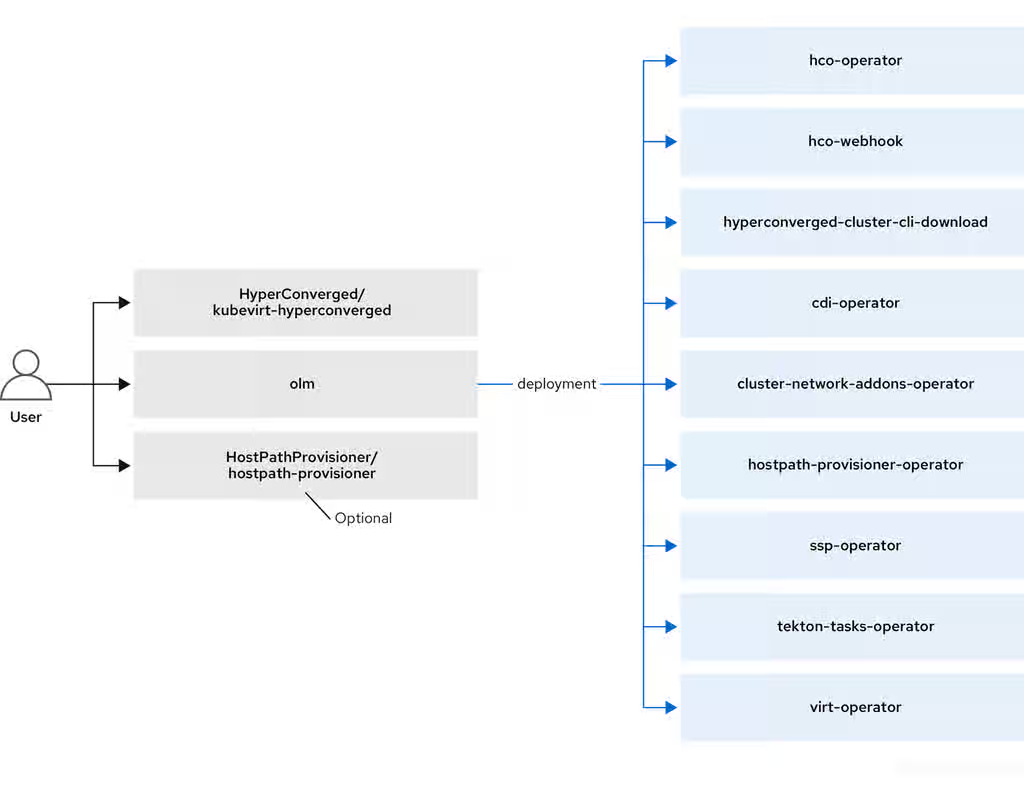
OpenShift Virtualization architecture consists of several Operators and components that manage the lifecycle, storage, networking, and scheduling of virtual machine workloads within the cluster.
The Operator Lifecycle Manager (OLM) deploys operator pods for each component of OpenShift Virtualization:
-
Compute:
virt-operator -
Storage:
cdi-operator -
Network:
cluster-network-addons-operator -
Scaling:
ssp-operator
OLM also deploys the hyperconverged-cluster-operator pod, which is responsible for the deployment, configuration, and life cycle of other components, and several helper pods: hco-webhook, and hyperconverged-cluster-cli-download.
After all operator pods are successfully deployed, you should create the HyperConverged custom resource (CR). The configurations set in the HyperConverged CR serve as the single source of truth and the entrypoint for OpenShift Virtualization, and guide the behavior of the CRs.
The HyperConverged CR creates corresponding CRs for the operators of all other components within its reconciliation loop. Each operator then creates resources such as daemon sets, config maps, and additional components for the OpenShift Virtualization control plane. For example, when the HyperConverged Operator (HCO) creates the KubeVirt CR, the OpenShift Virtualization Operator reconciles it and creates additional resources such as virt-controller, virt-handler, and virt-api.
The OLM deploys the Hostpath Provisioner (HPP) Operator, but it is not functional until you create a hostpath-provisioner CR.
1.4.1. About the HyperConverged Operator (HCO)
The HCO, hco-operator, provides a single entry point for deploying and managing OpenShift Virtualization and several helper operators with opinionated defaults. It also creates custom resources (CRs) for those operators.
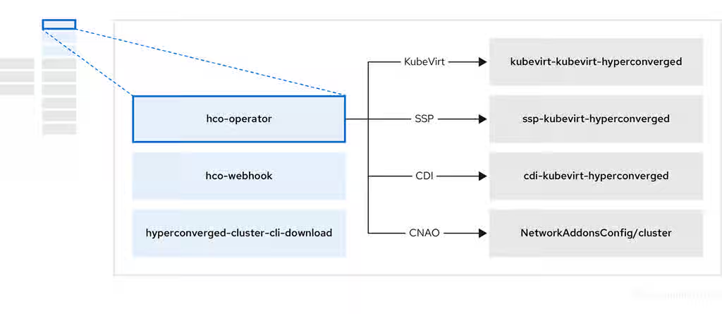
Table 1.8. HyperConverged Operator components
| Component | Description |
|---|---|
|
|
Validates the |
|
|
Provides the |
|
| Contains all operators, CRs, and objects needed by OpenShift Virtualization. |
|
| A Scheduling, Scale, and Performance (SSP) CR. This is automatically created by the HCO. |
|
| A Containerized Data Importer (CDI) CR. This is automatically created by the HCO. |
|
|
A CR that instructs and is managed by the |
1.4.2. About the Containerized Data Importer (CDI) Operator
The CDI Operator, cdi-operator, manages CDI and its related resources, which imports a virtual machine (VM) image into a persistent volume claim (PVC) by using a data volume.
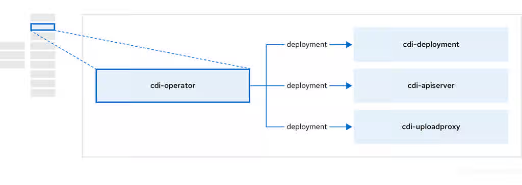
Table 1.9. CDI Operator components
| Component | Description |
|---|---|
|
| Manages the authorization to upload VM disks into PVCs by issuing secure upload tokens. |
|
| Directs external disk upload traffic to the appropriate upload server pod so that it can be written to the correct PVC. Requires a valid upload token. |
|
| Helper pod that imports a virtual machine image into a PVC when creating a data volume. |
1.4.3. About the Cluster Network Addons Operator
The Cluster Network Addons Operator, cluster-network-addons-operator, deploys networking components on a cluster and manages the related resources for extended network functionality.
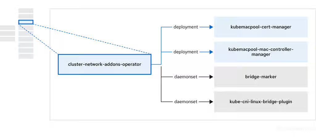
Table 1.10. Cluster Network Addons Operator components
| Component | Description |
|---|---|
|
| Manages TLS certificates of Kubemacpool’s webhooks. |
|
| Provides a MAC address pooling service for virtual machine (VM) network interface cards (NICs). |
|
| Marks network bridges available on nodes as node resources. |
|
| Installs Container Network Interface (CNI) plugins on cluster nodes, enabling the attachment of VMs to Linux bridges through network attachment definitions. |
1.4.4. About the Hostpath Provisioner (HPP) Operator
The HPP Operator, hostpath-provisioner-operator, deploys and manages the multi-node HPP and related resources.
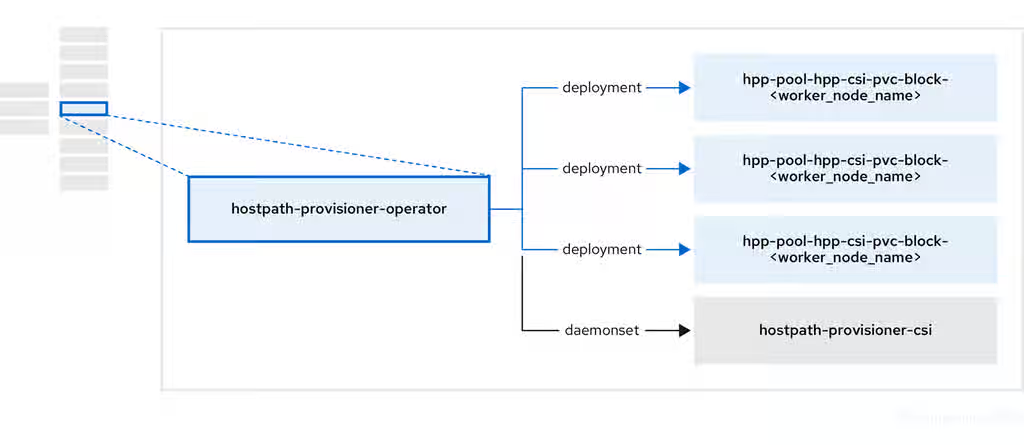
Table 1.11. HPP Operator components
| Component | Description |
|---|---|
|
| Provides a worker for each node where the HPP is designated to run. The pods mount the specified backing storage on the node. |
|
| Implements the Container Storage Interface (CSI) driver interface of the HPP. |
|
| Implements the legacy driver interface of the HPP. |
1.4.5. About the Scheduling, Scale, and Performance (SSP) Operator
The SSP Operator, ssp-operator, deploys the common templates, the related default boot sources, the pipeline tasks, and the template validator.
1.4.6. About the OpenShift Virtualization Operator
The OpenShift Virtualization Operator, virt-operator, deploys, upgrades, and manages OpenShift Virtualization without disrupting current virtual machine (VM) workloads. In addition, the OpenShift Virtualization Operator deploys the common instance types and common preferences.
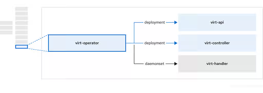
Table 1.12. virt-operator components
| Component | Description |
|---|---|
|
| HTTP API server that serves as the entry point for all virtualization-related flows. |
|
|
Observes the creation of a new VM instance object and creates a corresponding pod. When the pod is scheduled on a node, |
|
|
Monitors any changes to a VM and instructs |
|
|
Contains the VM that was created by the user as implemented by |
1.4.7. Additional resources
Chapter 2. Release notes
2.1. OpenShift Virtualization release notes
These release notes describe new features and enhancements, Technology Preview features, deprecated and removed features, fixed issues, and known issues for OpenShift Virtualization 4.21.
2.1.1. Supported guest operating systems
To view the supported guest operating systems for OpenShift Virtualization, see Certified Guest Operating Systems in Red Hat OpenStack Platform, Red Hat Virtualization, OpenShift Virtualization and Red Hat Enterprise Linux with KVM.
2.1.2. Microsoft Windows SVVP certification
OpenShift Virtualization is certified in Microsoft’s Windows Server Virtualization Validation Program (SVVP) to run Windows Server workloads.
The SVVP certification applies to:
- Red Hat Enterprise Linux CoreOS workers. In the Microsoft SVVP Catalog, they are named Red Hat OpenShift Container Platform 4.21.
- Intel and AMD CPUs.
2.1.3. New features and enhancements
- Remove the Migration Toolkit for Containers (MTC) Operator during the upgrade process
With this update, cluster administrators can optionally remove the MTC Operator when they upgrade from previous OpenShift Virtualization versions to version 4.21. MTC is end-of-life and no longer needed in OpenShift Virtualization version 4.21 to support live storage migration.
- IBM® Secure Execution for VMs on IBM Z® and IBM® LinuxONE is generally available
- IBM® Secure Execution for VMs on IBM Z® and IBM® LinuxONE is now generally available. This capability provides hardware based memory encryption that protects virtual machine workloads from access by the host or hypervisor environment. For more information, see Configuring IBM® Secure Execution virtual machines on IBM Z® and IBM® LinuxONE.
- OpenShift Virtualization on IBM Cloud® bare-metal nodes is generally available
Installing OpenShift Virtualization on IBM Cloud® bare-metal nodes is now generally available. This update provides the ability to install OpenShift Virtualization on IBM Cloud provisioned bare-metal nodes by using Assisted Installer.
- Custom MAC pool range configuration
With this update, cluster administrators can specify a custom MAC pool range for a OpenShift Virtualization environment, preventing potential MAC address conflicts with other virtualization solutions on the same network. This gives cluster administrators more control over network resources, ensuring greater network stability and resource management efficiency.
- Import VMs into OpenShift Virtualization while maintaining their previously assigned IP and MAC addresses
With this update, you can import VMs into OpenShift Virtualization, preserving their original IP and MAC addresses when connected to custom, primary layer 2 networks. This enhancement streamlines the import process, ensuring network consistency and a seamless transition of VMs, resulting in minimal disruption.
- Migrate VM disks to different storage classes
Previously, installation of Migration Toolkit for Containers (MTC) was required before migrating VM disks to different storage classes. This requirement no longer exists, as VM disk storage class migration is now native to OpenShift Virtualization.
In addition, it is no longer a requirement that the VMs you select for each bulk migration be in the same namespace.
- Defining
ClusterUserDefinedNetworkresources with a localnet topology With this update, you can create and manage
ClusterUserDefinedNetworkresources within the localnet topology, using the OpenShift Container Platform web console.- Enhancements for the virtual machines Search menu
With this update, the search interface is enhanced, making it more noticeable and user-friendly. A prominent Search button and an advanced search option are introduced, allowing users to initiate a search with either the primary button or the Enter key. This streamlines the user experience and improves overall search functionality.
- Search bar added to the Settings page
With this update, a search bar is added to the Virtualization → Settings page of the OpenShift Container Platform web console. This allows users to easily search for different settings contained within the Cluster, User, or Preview features tabs.
--preserve-sessionflag introduced to prevent unintentional VNC disconnectsAn optional
--preserve-sessionflag has been introduced for VMs. This flag prevents an existing VNC console connection from being disconnected if you attempt to start a new session.If you attempt to create a second connection to the VNC console by using the
virtctlCLI when this flag is set, an error is displayed and the connection fails.If you attempt to create a second connection to the VNC console by using the web console, a warning is displayed, and you are prompted to disconnect the existing session before you create the new session.
- Starting a virtual machine console from the tree-view
You can now start a virtual machine (VM) console session by clicking on the name of the running VM in the navigation panel, and then selecting Open Console.
- Define OVS bonding in the Node network configuration wizard
You can now define an Open vSwitch (OVS) Source Load Balancing (SLB) bonding interface when creating a node network configuration policy in the OpenShift Container Platform web console. Use the Uplink connection tab in the Node network configuration wizard to configure bond network interfaces that provide access to the external physical network to multiple VMs across shared bonded links.
For more information, see Managing policy from the web console.
- Viewing and changing the current memory overcommitment using the web console
You can view and change the memory overcommitment of the cluster from the Virtualization page of the web console.
- Self validation tab added to the Checkups page
With this update, cluster administrators can run a self-validation checkup on an OpenShift Container Platform cluster from the Self validation tab in the Virtualization → Checkups page of the web console. Users can download detailed results from the checkup as a ZIP file. This feature enables cluster administrators to execute extensive test suites on their clusters, helping to identify and address potential issues in advanced features and configurations.
- LiveMigration and Take snapshot actions added to the list of available bulk actions in the web console
With this update, cluster administrators can perform the following additional bulk actions:
- LiveMigration - live migration of multiple selected VMs to a different node.
Take snapshot - taking snapshots of multiple selected VMs.
- Web console Reset button now available
With this update, VM owners can force reboot their VMs by clicking Reset in the web console. This reboot process preserves user-customized data, such as hot plugged storage, by preserving the pod that contains the VM. This enhancement provides a more efficient and user-friendly experience, as users no longer need to manually manage the reboot process or risk losing their customized data.
- VNC console now offers access to function keys F1-F12
With this update, the VNC console now offers access to function keys F1-F12. This enhancement enables a smoother and more seamless experience for VM owners, by expanding the Send key functionality to include function keys.
- Integrate third-party solutions with dynamic plugins
With this update, cluster administrators can integrate third-party solutions into OpenShift Virtualization web console pages by using dynamic plugins. You can use dynamic plugins to add custom tabs or actions, including bulk operations for VM owners.
- Customizable action menu added for Kubevirt plugin
With this update, the Kubevirt plugin introduces a customizable action menu, which allows you to load custom actions from dynamic plugins. This enhancement also offers dynamic loading of local actions, and de-duplication of action lists, resulting in a more flexible user interface.
- New metric to list VM labels as Prometheus labels
The
kubevirt_vm_labelsmetric shows VM labels as Prometheus labels. You can configure the metric to expose and exclude specific labels by editing theallowlistandignorelistfields in thekubevirt-vm-labels-configconfig map.- New alerts in the OpenShift Virtualization runbooks
The following alerts for the OpenShift Virtualization Operator are now included in the OpenShift Virtualization runbooks:
-
DeprecatedMachineType -
GuestFilesystemAlmostOutOfSpace -
GuestVCPUQueueHighCritical -
GuestVCPUQueueHighWarning -
HCOGoldenImageWithNoArchitectureAnnotation -
HCOGoldenImageWithNoSupportedArchitecture -
HCOMultiArchGoldenImagesDisabled -
HCOOperatorConditionsUnhealthy -
HighNodeCPUFrequency -
KubeVirtVMGuestMemoryAvailableLow -
KubeVirtVMGuestMemoryPressure -
PersistentVolumeFillingUp -
VirtLauncherPodsStuckFailed -
VirtualMachineInstanceHasEphemeralHotplugVolume -
VirtualMachineStuckInUnhealthyState -
VirtualMachineStuckOnNode
-
2.1.4. Deprecated features
- The
HotplugVolumefeature gate is deprecated The
HotplugVolumefeature gate, which allows you to add storage without restarting your VM, is deprecated and will be removed in a future release. This feature gate will be replaced byDeclarativeHotplugVolumes.NoteDeclarativeHotplugVolumesdoes not support hot plugging ephemeral volumes. Ephemeral volumes are hot plugged to a VMI and do not persist in the owner VM. Existing ephemeral volumes that are hot plugged are automatically detached after you switch to theDeclarativeHotplugVolumesfeature gate.
2.1.5. Removed features
Removed features are no longer supported in OpenShift Virtualization.
- Legacy virtctl ssh target syntax removed
-
With this release, support for the
virtctl ssh type/name[.namespace]target syntax has been removed. You must specify the target by using an explicit resource type, such asvmi/<name>orvm/<name>. Scripts and automation that rely on the removed syntax must be updated.
- Support for
kubevirt-virtctlRPM removed -
With this release, support for the RHEL 8
kubevirt-virtctlRPM is removed and no longer supported.
2.1.6. Technology Preview features
Some features in this release are currently in Technology Preview. These experimental features are not intended for production use. Note the following scope of support on the Red Hat Customer Portal for these features:
Technology Preview Features Support Scope
- Golden image support for heterogeneous clusters (Technology Preview)
Golden image support is available for heterogeneous clusters, which enables you to create and use golden images for virtual machines in environments with differing node configurations. This capability is a Technology Preview feature.
- Custom video device support in virtual machines (Technology Preview)
You can now configure a custom video device type when creating a virtual machine. Configuring a custom device type overrides the default video configuration, and allows you to specify different video devices, based on your guest operating system requirements and performance needs. This capability is a Technology Preview feature.
2.1.7. Known issues
Some linked Jira tickets are accessible only with Red Hat credentials.
- VMs using the cnv-bridge CNI fail to live migrate after updates from 4.12
When you update from OpenShift Container Platform 4.12 to a newer minor version, virtual machines that use the
cnv-bridgeContainer Network Interface (CNI) fail to live migrate. As a consequence, live migration fails for affected VMs.To work around this problem, change the
spec.config.typefield in yourNetworkAttachmentDefinitionmanifest fromcnv-bridgetobridgebefore you perform the update. As a result, live migration succeeds for VMs that use the updated network attachment definitions.
- Red Hat OpenShift Service Mesh 3.1.1 and Istio 1.25 and later are incompatible with OpenShift Virtualization
Red Hat OpenShift Service Mesh 3.1.1 and Istio versions 1.25 and later are incompatible with OpenShift Virtualization 4.21 because the
traffic.sidecar.istio.io/kubevirtInterfacesannotation is deprecated. As a consequence, service mesh integration with OpenShift Virtualization can fail when you use these versions.To work around this problem, when you install Service Mesh for integration with OpenShift Virtualization, select Red Hat OpenShift Service Mesh version 3.0.4 and Istio 1.24.4 instead of the default versions that are displayed in the web console.
- Node labels remain after uninstalling OpenShift Virtualization
Uninstalling OpenShift Virtualization does not remove the
feature.node.kubevirt.ionode labels that OpenShift Virtualization creates. As a consequence, nodes can still appear as if they are configured for virtualization workloads.To work around this problem, manually remove the
feature.node.kubevirt.iolabels from affected nodes after you uninstall OpenShift Virtualization.
- Live migration fails when VM names exceed 47 characters
Live migration fails if a virtual machine name exceeds 47 characters. As a consequence, you cannot live migrate VMs with longer names.
To work around this problem, use VM names that are 47 characters or fewer when you create VMs that you plan to live migrate.
- Service account volume becomes invalid after VM migration
OpenShift Virtualization links a service account token in use by a pod to that specific pod by creating a disk image that contains the token. If you migrate a VM, the service account volume becomes invalid for the migrated VM. As a consequence, workloads that rely on that service account token can fail after migration.
To work around this problem, use user accounts instead of service accounts, because user account tokens are not bound to a specific pod.
- Upgrading to OpenShift Virtualization 4.21 when using wasp-agent
If you are upgrading OpenShift Virtualization from version 4.20 to 4.21 and using
wasp-agentto increase VM workload density, you must perform the following steps after you begin the upgrade:- Wait for the Machine Configuration Pool (MCP) to complete the updating of the infra nodes.
-
Edit the
KubeletConfigfile to remove thefailSwapOn: falsekey-value pair. - Wait for the MCP to finish updating the worker nodes.
- Duplicate boot sources created after enabling multi-architecture imports
When you enable the
spec.featureGates.enableMultiArchBootImageImportfeature gate after boot sources have already been imported, OpenShift Virtualization recreates the boot source import resources using architecture-suffixed names, such asfedora-amd64orfedora-arm64.The original, non-suffixed boot source resources are not automatically removed and remain in the
openshift-virtualization-os-imagesnamespace. This results in duplicate boot sources appearing in the web console and CLI. These stale resources continue to consume storage space because the associated PVCs orVolumeSnapshotsare retained.To work around this problem, manually delete the stale boot source resources:
-
Identify the currently active
DataSourceobjects that resolve to the PVCs orVolumeSnapshotsyou want to keep. Delete the older, non-suffixed
DataSourceobjects and the PVCs orVolumeSnapshotsthey reference.
-
Identify the currently active
2.1.8. Maintenance releases
2.1.8.1. OpenShift Virtualization 4.21.1 updates
OpenShift Virtualization 4.21.1 is now available with updates to packages and images that fix several bugs and add enhancements.
2.1.8.1.1. New features and enhancements
- OpenShift Virtualization on Google Cloud is generally available
Using OpenShift Virtualization on a Google Cloud cluster with bare-metal nodes is now generally available. For more information, see the following articles in the Red Hat Knowledgebase:
- Running OpenShift Virtualization on Google Cloud requires OpenShift Container Platform 4.21.5 and OpenShift Virtualization 4.21.1, or later versions.
- Resizing an attached Hyperdisk volume is not supported in RWX mode. For more information, see Content from docs.cloud.google.com is not included.Increase the capacity of a Hyperdisk volume in the Google Cloud documentation.
The Google Cloud platform, by default, has limitations that are incompatible with the capabilities of OpenShift Virtualization. You can override these limitations by contacting Google to request project-level allow list approval:
- Multi-writer mode (RWX) is currently not allowed for bare-metal machines. For more information, see Content from docs.cloud.google.com is not included.Limitations for sharing Hyperdisk volumes in multi-writer mode in the Google Cloud documentation.
- While most machine types default to 127 volumes per node, certain bare-metal machine types have lower volume attachment limits. For more information, see Content from docs.cloud.google.com is not included.Disk and capacity limits in the Google Cloud documentation and Volume Attachment Limit Per Node in the Red Hat Knowledgebase.
- Cross-cluster live migration for OpenShift Virtualization is generally available
Cross-cluster live migration is generally available for OpenShift Virtualization 4.21.1. You can now move the workloads of running virtual machines (VMs) from one OpenShift Container Platform cluster to another OpenShift Container Platform cluster without disruption.
2.1.8.2. OpenShift Virtualization 4.21.2 updates
OpenShift Virtualization 4.21.2 is now available with updates to packages and images that fix several bugs and add enhancements.
2.1.8.2.1. New features and enhancements
- OpenShift Virtualization with Google Cloud NetApp Volumes (GCNV) is generally available
OpenShift Virtualization on Google Cloud with Google Cloud NetApp Volumes (GCNV) storage is now generally available (GA). GCNV provides NFS-based shared storage that supports ReadWriteMany (RWX) access in Filesystem mode. The NetApp Trident CSI driver provisions GCNV storage volumes.
For more information, see the following articles in the Red Hat Knowledgebase:
- Storage configuration for OpenShift Virtualization with GCNV
OpenShift Virtualization with GCNV: Known errors and limitations
Important- Running OpenShift Virtualization with GCNV storage requires OpenShift Container Platform 4.21 and OpenShift Virtualization 4.21.2, or later versions.
- Only the Flex File service level is supported in this release. When creating storage pools, select the File storage type. Flex Unified is not supported.
-
Flex File volumes are NFS-only and support
volumeMode: Filesystemexclusively.volumeMode: Blockis not available with Flex File. -
GCNV Flex pools are limited to 50 volumes per pool. To support larger deployments, create multiple storage pools and list them all in the
TridentBackendConfigfile. For more information, see Content from docs.cloud.google.com is not included.GCNV storage pool limits. - Flex File pools can be Zonal or Regional. Regional pools replicate volumes across zones but only support default performance, not custom. For more information on service levels and performance, see Content from docs.cloud.google.com is not included.GCNV service levels.
Chapter 3. Getting started
3.1. Getting started with OpenShift Virtualization
Explore OpenShift Virtualization by taking guided tours, installing the Operator, and configuring a basic environment. Learn how to migrate from your current platform, then learn more about how to deploy and manage virtual machines (VMs) by following the additional resources links.
Cluster configuration procedures require cluster-admin privileges.
3.1.1. Getting started tour
The Getting started tour introduces several key aspects of using OpenShift Virtualization. There are two ways to start the tour.
Prerequisites
- You have access to the OpenShift Container Platform web console.
Procedure
- If you see the Welcome to OpenShift Virtualization dialog, click Start Tour.
- Otherwise, go to Virtualization → Overview → Settings → User → Getting started resources → Guided tour.
3.1.2. Quick start tours
You can explore several OpenShift Virtualization capabilities by taking quick start tours in the web console.
Prerequisites
- You have access to the OpenShift Container Platform web console.
Procedure
- Click the Help icon ? in the menu bar on the header of the OpenShift Container Platform web console.
-
Select Quick Starts. You can filter the list of tours by entering the keyword
virtualin the Filter field.
3.1.3. Migrating to OpenShift Virtualization
To migrate virtual machines from an external provider such as VMware vSphere, Red Hat OpenStack Platform (RHOSP), Red Hat Virtualization, or another OpenShift Container Platform cluster, use the Migration Toolkit for Virtualization (MTV). You can also migrate Open Virtual Appliance (OVA) files created by VMware vSphere.
Migration Toolkit for Virtualization is not part of OpenShift Virtualization and requires separate installation. For this reason, all links in this procedure lead outside of OpenShift Virtualization documentation.
Prerequisites
- The Migration Toolkit for Virtualization Operator is installed.
3.1.4. Additional resources
- Plan your bare-metal cluster for OpenShift Virtualization
- Prepare your cluster for OpenShift Virtualization
- Learn about storage volumes for VM disks
- Use a CSI-enabled storage provider
- Configure local storage for virtual machines
- Install the OpenShift Virtualization Operator
- Install the Kubernetes NMState Operator
- Specify nodes for virtual machines
-
Install and use the
virtctlcommand-line interface (CLI) tool - Create a VM from a Red Hat image
- Create a VM from an instance type
- Import a custom image from a web page
- Upload an image from your local machine
- Clone a persistent volume claim (PVC)
- Connect a VM to a Linux bridge network
- Connect a VM to an Open Virtual Network (OVN)-Kubernetes secondary network
- Connect a VM to a Single Root I/O Virtualization (SR-IOV) network
- Connect to a virtual machine console
- SSH access for virtual machines
- Connect to the desktop viewer by using the web console
- Manage a VM by using the web console
- Export a VM
- Review post-installation configuration options
- Configure storage options and automatic boot source updates
- Learn about monitoring and health checks
- Learn about live migration
- Back up and restore VMs by using the OpenShift API for Data Protection (OADP)
- Tune and scale your cluster
3.2. Using the CLI tools
You can manage OpenShift Virtualization resources by using the virtctl command-line tool. Virtual machine (VM) commands can also be used to manage virtual machine instances (VMIs) unless otherwise specified.
You can access and change VM disk images by using the libguestfs command-line tool. You deploy libguestfs by using the virtctl libguestfs command.
3.2.1. Installing the virtctl binary on RHEL 9 or later, Linux, Windows, or macOS
You can download the virtctl binary by using the OpenShift Container Platform web console and then install it on Red Hat Enterprise Linux (RHEL) 9 or later, Linux, Windows, or macOS.
Procedure
- Navigate to the Virtualization → Overview page in the web console.
-
Click the Download virtctl link to download the
virtctlbinary for your operating system. Install
virtctl:For RHEL and other Linux operating systems:
Decompress the archive file:
$ tar -xvf <virtctl-version-distribution.arch>.tar.gz
Run the following command to make the
virtctlbinary executable:$ chmod +x <path/virtctl-file-name>
Move the
virtctlbinary to a directory in yourPATHenvironment variable.You can check your path by running the following command:
$ echo $PATH
Set the
KUBECONFIGenvironment variable:$ export KUBECONFIG=/home/<user>/clusters/current/auth/kubeconfig
For Windows:
- Decompress the archive file.
-
Navigate the extracted folder hierarchy and double-click the
virtctlexecutable file to install the client. Move the
virtctlbinary to a directory in yourPATHenvironment variable.You can check your path by running the following command:
C:\> path
For macOS:
- Decompress the archive file.
Move the
virtctlbinary to a directory in yourPATHenvironment variable.You can check your path by running the following command:
echo $PATH
3.2.2. virtctl information commands
You can use the following virtctl information commands to view information about the virtctl client.
Table 3.1. Information commands
| Command | Description |
|---|---|
|
|
View the |
|
|
View a list of |
|
| View a list of options for a specific command. |
|
|
View a list of global command options for any |
3.2.3. VM information commands
You can use virtctl to view information about virtual machines (VMs) and virtual machine instances (VMIs).
Table 3.2. VM information commands
| Command | Description |
|---|---|
|
| View the file systems available on a guest machine. |
|
| View information about the operating systems on a guest machine. |
|
| View the logged-in users on a guest machine. |
3.2.4. VM manifest creation commands
You can use the following virtctl create commands to create manifests for virtual machines, instance types, and preferences.
Table 3.3. VM manifest creation commands
| Command | Description |
|---|---|
|
|
Create a |
|
| Create a VM manifest, specifying a name for the VM. |
|
| Create a VM manifest with a cloud-init configuration to create the selected user and either add an SSH public key from the supplied string, or a password from a file. |
|
| Create a VM manifest with a user and password combination injected from the selected secret. |
|
| Create a VM manifest with an SSH public key injected from the selected secret. |
|
|
Create a VM manifest, specifying a config map to use as the sysprep volume. The config map must contain a valid answer file named |
|
| Create a VM manifest that uses an existing cluster-wide instance type. |
|
| Create a VM manifest that uses an existing namespaced instance type. |
|
| Create a manifest for a cluster-wide instance type. |
|
| Create a manifest for a namespaced instance type. |
|
| Create a manifest for a cluster-wide VM preference, specifying a name for the preference. |
|
| Create a manifest for a namespaced VM preference. |
3.2.5. VM management commands
You can use the following virtctl commands to manage and migrate virtual machines (VMs) and VM instances (VMIs).
Table 3.4. VM management commands
| Command | Description |
|---|---|
|
| Start a VM. |
|
| Start a VM in a paused state. This option enables you to interrupt the boot process from the VNC console. |
|
| Stop a VM. |
|
| Force stop a VM. This option might cause data inconsistency or data loss. |
|
| Pause a VM. The machine state is kept in memory. |
|
| Unpause a VM. |
|
| Migrate a VM. |
|
| Cancel a VM migration. |
|
| Restart a VM. |
3.2.6. VM connection commands
You use can use the following virtctl commands to expose ports and connect to virtual machines (VMs) and VM instances (VMIs).
Table 3.5. VM connection commands
| Command | Description |
|---|---|
|
| Connect to the serial console of a VM. |
|
| Create a service that forwards a designated port of a VM and expose the service on the specified port of the node.
Example: |
|
| Copy a file from your machine to a VM. This command uses the private key of an SSH key pair. The VM must be configured with the public key. |
|
| Copy a file from a VM to your machine. This command uses the private key of an SSH key pair. The VM must be configured with the public key. |
|
| Open an SSH connection with a VM. This command uses the private key of an SSH key pair. The VM must be configured with the public key. |
|
| Connect to the VNC console of a VM.
You must have |
|
| Display the port number and connect manually to a VM by using any viewer through the VNC connection. |
|
| Specify a port number to run the proxy on the specified port, if that port is available. If a port number is not specified, the proxy runs on a random port. |
3.2.7. VM export commands
Use virtctl vmexport commands to create, download, or delete a volume exported from a VM, VM snapshot, or persistent volume claim (PVC). Certain manifests also contain a header secret, which grants access to the endpoint to import a disk image in a format that OpenShift Virtualization can use.
Table 3.6. VM export commands
| Command | Description |
|---|---|
|
|
Create a
|
|
|
Delete a |
|
|
Download the volume defined in a
Optional:
|
|
|
Create a |
|
| Retrieve the manifest for an existing export. The manifest does not include the header secret. |
|
| Create a VM export for a VM example, and retrieve the manifest. The manifest does not include the header secret. |
|
| Create a VM export for a VM snapshot example, and retrieve the manifest. The manifest does not include the header secret. |
|
| Retrieve the manifest for an existing export. The manifest includes the header secret. |
|
| Retrieve the manifest for an existing export in json format. The manifest does not include the header secret. |
|
| Retrieve the manifest for an existing export. The manifest includes the header secret and writes it to the file specified. |
3.2.8. Hot plug and hot unplug commands
You can use the following virtctl commands to add or remove resources from running virtual machines (VMs) and VM instances (VMIs).
Table 3.7. Hot plug and hot unplug commands
| Command | Description |
|---|---|
|
| Hot plug a data volume or persistent volume claim (PVC). Optional:
|
|
| Hot unplug a virtual disk. |
3.2.9. Image upload commands
You can use the following virtctl image-upload commands to upload a VM image to a data volume.
Table 3.8. Image upload commands
| Command | Description |
|---|---|
|
| Upload a VM image to a data volume that already exists. |
|
| Upload a VM image to a new data volume of a specified requested size. |
|
|
Upload a VM image to a new data volume and create an associated |
3.2.10. Deploying libguestfs by using virtctl
You can use the virtctl guestfs command to deploy an interactive container with libguestfs-tools and a persistent volume claim (PVC) attached to it.
Procedure
To deploy a container with
libguestfs-tools, mount the PVC, and attach a shell to it, run the following command:$ virtctl guestfs -n <namespace> <pvc_name>
ImportantThe
<pvc_name>argument is required. If you do not include it, an error message appears.
3.2.11. Libguestfs and virtctl guestfs commands
Libguestfs tools help you access and modify virtual machine (VM) disk images. You can use libguestfs tools to view and edit files in a guest, clone and build virtual machines, and format and resize disks.
You can also use the virtctl guestfs command and its sub-commands to modify, inspect, and debug VM disks on a PVC. To see a complete list of possible sub-commands, enter virt- on the command line and press the Tab key. For example:
| Command | Description |
|---|---|
|
| Edit a file interactively in your terminal. |
|
| Inject an ssh key into the guest and create a login. |
|
| See how much disk space is used by a VM. |
|
| See the full list of all RPMs installed on a guest by creating an output file containing the full list. |
|
|
Display the output file list of all RPMs created using the |
|
| Seal a virtual machine disk image to be used as a template. |
By default, virtctl guestfs creates a session with everything needed to manage a VM disk. However, the command also supports several flag options if you want to customize the behavior:
| Flag Option | Description |
|---|---|
|
|
Provides help for |
|
| To use a PVC from a specific namespace.
If you do not use the
If you do not include a |
|
|
Lists the
You can configure the container to use a custom image by using the |
|
|
Indicates that
By default,
If a cluster does not have any
If not set, the |
|
|
Shows the pull policy for the
You can also overwrite the image’s pull policy by setting the |
The command also checks if a PVC is in use by another pod, in which case an error message appears. However, once the libguestfs-tools process starts, the setup cannot avoid a new pod using the same PVC. You must verify that there are no active virtctl guestfs pods before starting the VM that accesses the same PVC.
The virtctl guestfs command accepts only a single PVC attached to the interactive pod.
3.2.12. Additional resources
Chapter 4. Installing
4.1. Preparing your cluster for OpenShift Virtualization
Review platform compatibility information before you install OpenShift Virtualization. For detailed system requirements, see "Hardware, software, and operational requirements" in the Additional resources section.
4.1.1. Compatible platforms
OpenShift Virtualization supports bare-metal servers, ARM64-based systems, and IBM Z® or IBM® LinuxONE systems in logical partitions.
- Compatible platforms
- On-premise bare-metal servers. For more information, see "Planning a bare-metal cluster for OpenShift Virtualization" in the Additional resources section.
-
Bare-metal clusters installed on ARM64-based (
arm64, also known asaarch64) systems. - IBM Z® or IBM® LinuxONE (s390x architecture) systems where an OpenShift Container Platform cluster is installed in logical partitions (LPARs). For more information, see "Preparing to install on IBM Z and IBM LinuxONE" in the Additional resources section.
4.1.2. Cloud platforms
OpenShift Virtualization is compatible with various public cloud platforms. Each platform has specific storage options available.
| Vendor | Status | Storage | Resources |
|---|---|---|---|
| Amazon Web Services (AWS) | GA |
|
|
| Red Hat OpenShift Service on AWS (ROSA) | GA |
|
|
| Oracle Cloud Infrastructure (OCI) | GA |
|
|
| Azure Red Hat OpenShift (ARO) | GA |
|
|
| Google Cloud | GA, as of OpenShift Virtualization 4.21.1 |
|
|
Bare-metal instances or servers offered by other cloud providers are not supported.
For platform-specific networking information, see "Networking overview" in the Additional resources section.
4.1.3. OpenShift Virtualization on AWS bare metal
You can run OpenShift Virtualization on an Amazon Web Services (AWS) bare metal OpenShift Container Platform cluster.
OpenShift Virtualization is also supported on Red Hat OpenShift Service on AWS (ROSA) Classic clusters, which have the same configuration requirements as AWS bare-metal clusters.
4.1.4. ARM64 compatibility
OpenShift Virtualization on ARM64 systems is generally available (GA) with specific limitations for operating systems and live migration.
Before using OpenShift Virtualization on an ARM64-based system, consider the following limitations:
- Operating system
- Only Linux-based guest operating systems are supported.
- All virtualization limitations for RHEL also apply to OpenShift Virtualization. For more information, see How virtualization on ARM64 differs from AMD64 and Intel 64 in the RHEL documentation.
- Live migration
- Live migration is not supported on ARM64-based OpenShift Container Platform clusters.
- Hotplug is not supported on ARM64-based clusters because it depends on live migration.
- VM creation
- RHEL 10 supports instance types and preferences, but not templates.
- RHEL 9 supports templates, instance types, and preferences.
4.1.5. IBM Z and IBM LinuxONE compatibility
You can use OpenShift Virtualization in an OpenShift Container Platform cluster that is installed in logical partitions (LPARs) on an IBM Z® or IBM® LinuxONE (s390x architecture) system.
Some features are not currently available on s390x architecture, while others require workarounds or procedural changes. These lists are subject to change.
- Currently unavailable features
The following features are currently not available on
s390xarchitecture:- Memory hot plugging and hot unplugging
- Node Health Check Operator
- SR-IOV Operator
- PCI passthrough
- OpenShift Virtualization cluster checkup framework
- OpenShift Virtualization on a cluster installed in FIPS mode
- IPv6
- IBM® Storage scale
- Hosted control planes for OpenShift Virtualization
VM pages using HugePages
The following features are not applicable on
s390xarchitecture:- virtual Trusted Platform Module (vTPM) devices
- UEFI mode for VMs
- USB host passthrough
- Configuring virtual GPUs
- Creating and managing Windows VMs
- Hyper-V
- Functionality differences
The following features are available for use on s390x architecture but function differently or require procedural changes:
- When deleting a virtual machine by using the web console, the grace period option is ignored. For more information, see "Deleting a virtual machine by using the web console" in the Additional resources section.
-
When configuring the default CPU model, the
spec.defaultCPUModelvalue is"gen15b"for an IBM Z cluster. For more information, see "Configuring the default CPU model" in the Additional resources section. -
When configuring a downward metrics device, if you use a VM preference, the
spec.preference.namevalue must be set torhel.9.s390xor another available preference with the format*.s390x. For more information, see "Configuring a downward metrics device" in the Additional resources section. -
When creating virtual machines from instance types, you are not allowed to set
spec.domain.memory.maxGuestbecause memory hot plugging is not supported on IBM Z®. For more information, see "Creating virtual machines from instance types" in the Additional resources section. -
Prometheus queries for VM guests could have inconsistent outcome in comparison to
x86.
4.1.6. Important considerations for any platform
Before installing OpenShift Virtualization, note key considerations about installation methods, storage, IPv6, and FIPS mode.
- Installation method considerations
- You can use any installation method, including user-provisioned, installer-provisioned, or Assisted Installer, to deploy OpenShift Container Platform. However, the installation method and the cluster topology might affect OpenShift Virtualization functionality, such as snapshots or live migration. For more information about live migration, see "Hardware, software, and operational requirements" in the Additional resources section.
- Red Hat OpenShift Data Foundation
- If you deploy OpenShift Virtualization with Red Hat OpenShift Data Foundation, you must create a dedicated storage class for Windows virtual machine disks. For more information, see "Optimizing ODF PersistentVolumes for Windows VMs" in the Additional resources section.
- IPv6
- OpenShift Virtualization support for single-stack IPv6 clusters is limited to the OVN-Kubernetes localnet and Linux bridge Container Network Interface (CNI) plugins.
{FeatureName} is a Technology Preview feature only. Technology Preview features are not supported with Red Hat production service level agreements (SLAs) and might not be functionally complete. Red Hat does not recommend using them in production. These features provide early access to upcoming product features, enabling customers to test functionality and provide feedback during the development process.
For more information about the support scope of Red Hat Technology Preview features, see Technology Preview Features Support Scope.
- FIPS mode
- If you install your cluster in FIPS mode, no additional setup is required for OpenShift Virtualization. For more information, see "Installing a FIPS-compliant cluster" in the Additional resources section.
4.1.7. Object maximums
Consider tested object maximums for both OpenShift Container Platform and OpenShift Virtualization when planning your cluster.
- OpenShift Container Platform
- See "OpenShift Container Platform object maximums" in the Additional resources section.
- OpenShift Virtualization
- See "OpenShift Virtualization supported limits" in the Additional resources section.
4.1.8. Additional resources
- Hardware, software, and operational requirements
- Planning a bare-metal cluster for OpenShift Virtualization
- Preparing to install on IBM Z and IBM LinuxONE
- Installing a cluster on AWS with customizations
- OpenShift Container Platform object maximums
- OpenShift Virtualization supported limits
- Installing a FIPS-compliant cluster
- Configure CPU models
- Deleting a virtual machine by using the web console
- Configuring a downward metrics device
- Creating virtual machines from instance types
- Networking overview
- Connecting a virtual machine to an OVN-Kubernetes secondary network
- Exposing a virtual machine by using a service
- Optimizing ODF PersistentVolumes for Windows VMs
- Content from docs.cloud.google.com is not included.GCNV service levels
- Glossary of common terms for OpenShift Container Platform storage
4.2. Hardware, software, and operational requirements
Review the hardware, software, and operational requirements for OpenShift Virtualization, including CPU, OS, storage, cluster sizing, and live migration.
4.2.1. CPU requirements
OpenShift Virtualization requires CPUs supported by Red Hat Enterprise Linux (RHEL) 9 with specific virtualization extensions enabled.
- CPU requirements for OpenShift Virtualization
- Must be supported by Red Hat Enterprise Linux (RHEL) 9. See This content is not included.Red Hat Ecosystem Catalog for supported CPUs.
NoteIf your worker nodes have different CPUs, live migration failures might occur because different CPUs have different capabilities. You can mitigate this issue by ensuring that your worker nodes have CPUs with the appropriate capacity and by configuring node affinity rules for your virtual machines.
For more information, see "Configuring a required node affinity rule" in the Additional resources section.
-
Supports AMD64, Intel 64-bit (x86-64-v2), IBM Z® (
s390x), or ARM64-based (arm64oraarch64) architectures and their respective CPU extensions. -
Intel VT-x, AMD-V, or ARM virtualization extensions are enabled, or
s390xvirtualization support is enabled. - NX (no execute) flag is enabled.
-
If you use
s390xarchitecture, the default CPU model is set togen15b. For more information, see "Configuring the default CPU model" in the Additional resources section.
4.2.2. Operating system requirements
OpenShift Virtualization requires Red Hat Enterprise Linux CoreOS (RHCOS) on worker nodes. RHEL worker nodes are not supported.
For more information, see "About RHCOS" in the Additional resources section.
4.2.3. Storage requirements
OpenShift Virtualization requires OpenShift Container Platform-supported storage with specific configuration for VM workloads and snapshots.
- Storage requirements for OpenShift Virtualization
- Storage must be supported by OpenShift Container Platform. For more information, see "Optimizing storage" in the Additional resources section.
You must create a default OpenShift Virtualization or OpenShift Container Platform storage class. The purpose of this is to address the unique storage needs of VM workloads and offer optimized performance, reliability, and user experience. If both OpenShift Virtualization and OpenShift Container Platform default storage classes exist, the OpenShift Virtualization class takes precedence when creating VM disks.
NoteTo mark a storage class as the default for virtualization workloads, set the annotation
storageclass.kubevirt.io/is-default-virt-classto"true".-
If the storage provisioner supports snapshots, you must associate a
VolumeSnapshotClassobject with the default storage class.
4.2.3.1. About volume and access modes for virtual machine disks
If you use the storage API with known storage providers, the volume and access modes are selected automatically. However, if you use a storage class that does not have a storage profile, you must configure the volume and access mode.
For a list of known storage providers for OpenShift Virtualization, see the Red Hat Ecosystem Catalog.
For best results, use the ReadWriteMany (RWX) access mode and the Block volume mode. This is important for the following reasons:
-
ReadWriteMany(RWX) access mode is required for live migration. The
Blockvolume mode performs significantly better than theFilesystemvolume mode. This is because theFilesystemvolume mode uses more storage layers, including a file system layer and a disk image file. These layers are not necessary for VM disk storage.For example, if you use Red Hat OpenShift Data Foundation, Ceph RBD volumes are preferable to CephFS volumes.
You cannot live migrate virtual machines with the following configurations:
-
Storage volume with
ReadWriteOnce(RWO) access mode - Passthrough features such as GPUs
Set the evictionStrategy field to None for these virtual machines. The None strategy powers down VMs during node reboots.
4.2.4. Physical resource overhead requirements
OpenShift Virtualization is an add-on to OpenShift Container Platform and imposes additional overhead that you must account for when planning a cluster.
Each cluster machine must accommodate the following overhead requirements in addition to the OpenShift Container Platform requirements. Oversubscribing the physical resources in a cluster can affect performance.
The numbers noted in this documentation are based on Red Hat’s test methodology and setup. These numbers can vary based on your own individual setup and environments.
4.2.4.1. Memory overhead
Calculate the memory overhead values for OpenShift Virtualization by using the equations below.
- Cluster memory overhead
Memory overhead per infrastructure node ≈ 150 MiB
Memory overhead per worker node ≈ 360 MiB
Additionally, OpenShift Virtualization environment resources require a total of 2179 MiB of RAM that is spread across all infrastructure nodes.
- Virtual machine memory overhead
Memory overhead per virtual machine ≈ (0.002 × requested memory) \ + 218 MiB \ + 8 MiB × (number of vCPUs) \ + 16 MiB × (number of graphics devices) \ + (additional memory overhead)-
218 MiBis required for the processes that run in thevirt-launcherpod. -
8 MiB × (number of vCPUs)refers to the number of virtual CPUs requested by the virtual machine. -
16 MiB × (number of graphics devices)refers to the number of virtual graphics cards requested by the virtual machine. Additional memory overhead:
- If your environment includes a Single Root I/O Virtualization (SR-IOV) network device or a Graphics Processing Unit (GPU), allocate 1 GiB additional memory overhead for each device.
- If Secure Encrypted Virtualization (SEV) is enabled, add 256 MiB.
- If Trusted Platform Module (TPM) is enabled, add 53 MiB.
-
4.2.4.2. CPU overhead
Calculate the cluster processor overhead requirements for OpenShift Virtualization by using the equation below. The CPU overhead per virtual machine depends on your individual setup.
- Cluster CPU overhead
CPU overhead for infrastructure nodes ≈ 4 cores
OpenShift Virtualization increases the overall utilization of cluster level services such as logging, routing, and monitoring. To account for this workload, ensure that nodes that host infrastructure components have capacity allocated for 4 additional cores (4000 millicores) distributed across those nodes.
CPU overhead for worker nodes ≈ 2 cores + CPU overhead per virtual machine
Each worker node that hosts virtual machines must have capacity for 2 additional cores (2000 millicores) for OpenShift Virtualization management workloads in addition to the CPUs required for virtual machine workloads.
- Virtual machine CPU overhead
- If dedicated CPUs are requested, there is a 1:1 impact on the cluster CPU overhead requirement. Otherwise, there are no specific rules about how many CPUs a virtual machine requires.
4.2.4.3. Storage overhead
Use the guidelines below to estimate storage overhead requirements for your OpenShift Virtualization environment.
- Cluster storage overhead
Aggregated storage overhead per node ≈ 10 GiB
10 GiB is the estimated on-disk storage impact for each node in the cluster when you install OpenShift Virtualization.
- Virtual machine storage overhead
- Storage overhead per virtual machine depends on specific requests for resource allocation within the virtual machine. The request could be for ephemeral storage on the node or storage resources hosted elsewhere in the cluster. OpenShift Virtualization does not currently allocate any additional ephemeral storage for the running container itself.
- Example
- As a cluster administrator, if you plan to host 10 virtual machines in the cluster, each with 1 GiB of RAM and 2 vCPUs, the memory impact across the cluster is 11.68 GiB. The estimated on-disk storage impact for each node in the cluster is 10 GiB and the CPU impact for worker nodes that host virtual machine workloads is a minimum of 2 cores.
4.2.5. Single-node OpenShift differences
You can install OpenShift Virtualization on single-node OpenShift.
However, you should be aware that Single-node OpenShift does not support the following features:
- High availability
- Pod disruption
- Live migration
- Virtual machines or templates that have an eviction strategy configured
4.2.6. Object maximums
Consider tested object maximums for both OpenShift Container Platform and OpenShift Virtualization when planning your cluster.
- OpenShift Container Platform
- See "OpenShift Container Platform object maximums" in the Additional resources section.
- OpenShift Virtualization
- See "OpenShift Virtualization supported limits" in the Additional resources section.
4.2.7. Live migration requirements
Live migration requires shared storage, sufficient resources, and compatible CPUs across nodes.
- Live migration requirements
-
Shared storage with
ReadWriteMany(RWX) access mode. Sufficient RAM and network bandwidth.
NoteYou must ensure that there is enough memory request capacity in the cluster to support node drains that result in live migrations. You can determine the approximate required spare memory by using the following calculation:
Product of (Maximum number of nodes that can drain in parallel) and (Highest total VM memory request allocations across nodes)
The default number of migrations that can run in parallel in the cluster is 5. For more information, see "Configuring live migration" in the Additional resources section.
- If the virtual machine uses a host model CPU, the nodes must support the virtual machine’s host model CPU.
-
Shared storage with
A dedicated Multus network for live migration is highly recommended. For more information, see "Using a dedicated network for live migration" in the Additional resources section. A dedicated network minimizes the effects of network saturation on tenant workloads during migration.
4.2.8. Cluster high availability options
Configure high availability (HA) for your cluster using installer-provisioned infrastructure (IPI), Node Health Check Operator, or manual monitoring.
- Methods of configuring HA
- Automatic high availability for installer-provisioned infrastructure is available by deploying machine health checks. For more information, see "Installer-provisioned infrastructure installation overview" and "About machine health checks" in the Additional resources section.
NoteIn OpenShift Container Platform clusters installed using installer-provisioned infrastructure and with a properly configured
MachineHealthCheckresource, if a node fails the machine health check and becomes unavailable to the cluster, it is recycled. What happens next with VMs that ran on the failed node depends on a series of conditions. See the "Run strategies" documentation for more detailed information about the potential outcomes and how run strategies affect those outcomes.Currently, installer-provisioned infrastructure is not supported on IBM Z®.
Automatic high availability for both IPI and non-IPI is available by using the Node Health Check Operator on the OpenShift Container Platform cluster to deploy the
NodeHealthCheckcontroller. The controller identifies unhealthy nodes and uses a remediation provider, such as the Self Node Remediation Operator or Fence Agents Remediation Operator, to remediate the unhealthy nodes. For more information on remediation, fencing, and maintaining nodes, see the This content is not included.Workload Availability for Red Hat OpenShift documentation.NoteFence Agents Remediation uses supported fencing agents to reset failed nodes faster than the Self Node Remediation Operator. This improves overall virtual machine high availability. For more information, see the OpenShift Virtualization - Fencing and VM High Availability Guide knowledgebase article.
High availability for any platform is available by using either a monitoring system or a qualified human to monitor node availability. When a node is lost, shut it down and run
oc delete node <lost_node>.NoteWithout an external monitoring system or a qualified human monitoring node health, virtual machines lose high availability.
4.2.9. Additional resources
- Configuring a required node affinity rule
- About RHCOS
- Optimizing storage
- This content is not included.Red Hat Ecosystem Catalog
- Configuring live migration
- Using a dedicated network for live migration
- Run strategies
- OpenShift Container Platform object maximums
- OpenShift Virtualization supported limits
- Installer-provisioned infrastructure installation overview
- About machine health checks
4.3. Installing OpenShift Virtualization
Install OpenShift Virtualization to add virtualization functionality to your OpenShift Container Platform cluster.
If you install OpenShift Virtualization in a restricted environment with no internet connectivity, you must configure Operator Lifecycle Manager (OLM) for a disconnected environment.
If you have limited internet connectivity, you can configure proxy support in OLM to access the software catalog.
4.3.1. Installing the OpenShift Virtualization Operator by using the web console
You can deploy the OpenShift Virtualization Operator by using the OpenShift Container Platform web console.
Prerequisites
- Install OpenShift Container Platform 4.21 on your cluster.
-
Log in to the OpenShift Container Platform web console as a user with
cluster-adminpermissions.
Procedure
- From the Administrator perspective, click Ecosystem → Software Catalog.
- In the Filter by keyword field, type Virtualization.
- Select the OpenShift Virtualization Operator tile with the Red Hat source label.
- Read the information about the Operator and click Install.
On the Install Operator page:
- Select stable from the list of available Update Channel options. This ensures that you install the version of OpenShift Virtualization that is compatible with your OpenShift Container Platform version.
For Installed Namespace, ensure that the Operator recommended namespace option is selected. This installs the Operator in the mandatory
openshift-cnvnamespace, which is automatically created if it does not exist.WarningAttempting to install the OpenShift Virtualization Operator in a namespace other than
openshift-cnvcauses the installation to fail.For Approval Strategy, it is highly recommended that you select Automatic, which is the default value, so that OpenShift Virtualization automatically updates when a new version is available in the stable update channel.
Selecting the Manual approval strategy is not recommended, as it poses a high risk to cluster support and functionality. Only select Manual if you fully understand these risks and cannot use Automatic.
WarningBecause OpenShift Virtualization is only supported when used with the corresponding OpenShift Container Platform version, missing OpenShift Virtualization updates can cause your cluster to become unsupported.
-
Click Install to make the Operator available to the
openshift-cnvnamespace. - When the Operator installs successfully, click Create HyperConverged.
- Optional: Configure Infra and Workloads node placement options for OpenShift Virtualization components.
- Click Create to launch OpenShift Virtualization.
Verification
- Navigate to the Workloads → Pods page and monitor the OpenShift Virtualization pods until they are all Running. After all the pods display the Running state, you can use OpenShift Virtualization.
4.3.2. Subscribing to the OpenShift Virtualization catalog by using the CLI
Before you install OpenShift Virtualization, you must subscribe to the OpenShift Virtualization catalog. Subscribing gives the openshift-cnv namespace access to the OpenShift Virtualization Operators.
To subscribe, configure Namespace, OperatorGroup, and Subscription objects by applying a single manifest to your cluster.
Prerequisites
- Install OpenShift Container Platform 4.21 on your cluster.
-
Install the OpenShift CLI (
oc). -
Log in as a user with
cluster-adminprivileges.
Procedure
Create a YAML file that contains the following manifest:
apiVersion: v1 kind: Namespace metadata: name: openshift-cnv labels: openshift.io/cluster-monitoring: "true" --- apiVersion: operators.coreos.com/v1 kind: OperatorGroup metadata: name: kubevirt-hyperconverged-group namespace: openshift-cnv spec: targetNamespaces: - openshift-cnv --- apiVersion: operators.coreos.com/v1alpha1 kind: Subscription metadata: name: hco-operatorhub namespace: openshift-cnv spec: source: redhat-operators sourceNamespace: openshift-marketplace name: kubevirt-hyperconverged startingCSV: kubevirt-hyperconverged-operator.v4.21.8 channel: "stable"Using the
stablechannel ensures that you install the version of OpenShift Virtualization that is compatible with your OpenShift Container Platform version.Create the required
Namespace,OperatorGroup, andSubscriptionobjects for OpenShift Virtualization by running the following command:$ oc apply -f <filename>.yaml
Verification
You must verify that the subscription creation was successful before you can proceed with installing OpenShift Virtualization.
Check that the
ClusterServiceVersion(CSV) object was created successfully. Run the following command and verify the output:$ oc get csv -n openshift-cnv
If the CSV was created successfully, the output shows an entry that contains a
NAMEvalue ofkubevirt-hyperconverged-operator-*, aDISPLAYvalue ofOpenShift Virtualization, and aPHASEvalue ofSucceeded, as shown in the following example output:Example output:
NAME                                       DISPLAY                    VERSION   REPLACES                                   PHASE
kubevirt-hyperconverged-operator.v4.21.8   OpenShift Virtualization   4.21.8    kubevirt-hyperconverged-operator.v4.20.0   Succeeded
Check that the
HyperConvergedcustom resource (CR) has the correct version. Run the following command and verify the output:$ oc get hco -n openshift-cnv kubevirt-hyperconverged -o json | jq .status.versions
Example output:
{ "name": "operator", "version": "4.21.8" }Verify the
HyperConvergedCR conditions. Run the following command and check the output:$ oc get hco kubevirt-hyperconverged -n openshift-cnv -o json | jq -r '.status.conditions[] | {type,status}'Example output:
{
  "type": "ReconcileComplete",
  "status": "True"
}
{
  "type": "Available",
  "status": "True"
}
{
  "type": "Progressing",
  "status": "False"
}
{
  "type": "Degraded",
  "status": "False"
}
{
  "type": "Upgradeable",
  "status": "True"
}
4.3.3. Deploying the OpenShift Virtualization Operator by using the CLI
You can deploy the OpenShift Virtualization Operator by using the oc CLI.
Prerequisites
-
Install the OpenShift CLI (
oc). -
Subscribe to the OpenShift Virtualization catalog in the
openshift-cnvnamespace. -
Log in as a user with
cluster-adminprivileges.
Procedure
Create a YAML file that contains the following manifest:
apiVersion: hco.kubevirt.io/v1beta1
kind: HyperConverged
metadata:
  name: kubevirt-hyperconverged
  namespace: openshift-cnv
spec:
Deploy the OpenShift Virtualization Operator by running the following command:
$ oc apply -f <file_name>.yaml
Verification
Ensure that OpenShift Virtualization deployed successfully by watching the
PHASEof the cluster service version (CSV) in theopenshift-cnvnamespace. Run the following command:$ watch oc get csv -n openshift-cnv
The following output displays if deployment was successful:
NAME                                      DISPLAY                    VERSION   REPLACES   PHASE
kubevirt-hyperconverged-operator.v4.21.8   OpenShift Virtualization   4.21.8                Succeeded
4.3.4. Additional resources
4.4. Uninstalling OpenShift Virtualization
You can uninstall OpenShift Virtualization by using the web console or the command-line interface (CLI) to delete OpenShift Virtualization workloads, the Operator, and its resources.
To uninstall OpenShift Virtualization, perform the following tasks:
-
Delete the
HyperConvergedCR. - Delete the OpenShift Virtualization Operator.
-
Delete the
openshift-cnvnamespace. - Delete the OpenShift Virtualization custom resource definitions (CRDs).
4.4.1. Prerequisites
- Delete all virtual machine instances. You cannot uninstall OpenShift Virtualization while its workloads remain on the cluster.
4.4.2. Deleting the HyperConverged custom resource
To uninstall OpenShift Virtualization, you first delete the HyperConverged custom resource (CR).
Prerequisites
-
You have access to an OpenShift Container Platform cluster using an account with
cluster-adminpermissions.
Procedure
- Navigate to the Ecosystem → Installed Operators page.
- Select the OpenShift Virtualization Operator.
- Click the OpenShift Virtualization Deployment tab.
-
Click the Options menu
 beside
 kubevirt-hyperconvergedand select Delete HyperConverged. - Click Delete in the confirmation window.
4.4.3. Deleting Operators from a cluster using the web console
Cluster administrators can delete installed Operators from a selected namespace by using the web console.
Prerequisites
-
You have access to the OpenShift Container Platform cluster web console using an account with
cluster-adminpermissions.
Procedure
- Navigate to the Ecosystem → Installed Operators page.
- Scroll or enter a keyword into the Filter by name field to find the Operator that you want to remove. Then, click on it.
On the right side of the Operator Details page, select Uninstall Operator from the Actions list.
An Uninstall Operator? dialog box is displayed.
Select Uninstall to remove the Operator, Operator deployments, and pods. Following this action, the Operator stops running and no longer receives updates.
NoteThis action does not remove resources managed by the Operator, including custom resource definitions (CRDs) and custom resources (CRs). Dashboards and navigation items enabled by the web console and off-cluster resources that continue to run might need manual clean up. To remove these after uninstalling the Operator, you might need to manually delete the Operator CRDs.
4.4.4. Deleting a namespace using the web console
You can delete a namespace by using the OpenShift Container Platform web console.
Prerequisites
-
You have access to the OpenShift Container Platform cluster using an account with
cluster-adminpermissions.
Procedure
- Navigate to Administration → Namespaces.
- Locate the namespace that you want to delete in the list of namespaces.
-
On the far right side of the namespace listing, select Delete Namespace from the Options menu
.
- When the Delete Namespace pane opens, enter the name of the namespace that you want to delete in the field.
- Click Delete.
4.4.5. Deleting OpenShift Virtualization custom resource definitions
You can delete the OpenShift Virtualization custom resource definitions (CRDs) by using the web console.
Prerequisites
-
You have access to the OpenShift Container Platform cluster using an account with
cluster-adminpermissions.
Procedure
- Navigate to Administration → CustomResourceDefinitions.
-
Select the Label filter and enter
operators.coreos.com/kubevirt-hyperconverged.openshift-cnvin the Search field to display the OpenShift Virtualization CRDs. -
Click the Options menu
beside each CRD and select Delete CustomResourceDefinition.
4.4.6. Uninstalling OpenShift Virtualization by using the CLI
You can uninstall OpenShift Virtualization by using the OpenShift CLI (oc).
Prerequisites
-
You have access to the OpenShift Container Platform cluster using an account with
cluster-adminpermissions. -
You have installed the OpenShift CLI (
oc). - You have deleted all virtual machines and virtual machine instances. You cannot uninstall OpenShift Virtualization while its workloads remain on the cluster.
Procedure
Delete the
HyperConvergedcustom resource:$ oc delete HyperConverged kubevirt-hyperconverged -n openshift-cnv
Delete the OpenShift Virtualization Operator subscription:
$ oc delete subscription hco-operatorhub -n openshift-cnv
Delete the OpenShift Virtualization
ClusterServiceVersionresource:$ oc delete csv -n openshift-cnv -l operators.coreos.com/kubevirt-hyperconverged.openshift-cnv
Delete the OpenShift Virtualization namespace:
$ oc delete namespace openshift-cnv
List the OpenShift Virtualization custom resource definitions (CRDs) by running the
oc delete crdcommand with thedry-runoption:$ oc delete crd --dry-run=client -l operators.coreos.com/kubevirt-hyperconverged.openshift-cnv
Example output:
customresourcedefinition.apiextensions.k8s.io "cdis.cdi.kubevirt.io" deleted (dry run)
customresourcedefinition.apiextensions.k8s.io "hostpathprovisioners.hostpathprovisioner.kubevirt.io" deleted (dry run)
customresourcedefinition.apiextensions.k8s.io "hyperconvergeds.hco.kubevirt.io" deleted (dry run)
customresourcedefinition.apiextensions.k8s.io "kubevirts.kubevirt.io" deleted (dry run)
customresourcedefinition.apiextensions.k8s.io "networkaddonsconfigs.networkaddonsoperator.network.kubevirt.io" deleted (dry run)
customresourcedefinition.apiextensions.k8s.io "ssps.ssp.kubevirt.io" deleted (dry run)
customresourcedefinition.apiextensions.k8s.io "tektontasks.tektontasks.kubevirt.io" deleted (dry run)
Delete the CRDs by running the
oc delete crdcommand without thedry-runoption:$ oc delete crd -l operators.coreos.com/kubevirt-hyperconverged.openshift-cnv
4.4.7. Additional resources
-
Deleting the
HyperConvergedcustom resource - Deleting Operators from a cluster using the web console
- Deleting a namespace using the web console
- Deleting OpenShift Virtualization custom resource definitions
- Deleting a virtual machine using the web console
- Deleting a standalone virtual machine instance using the CLI
4.5. Installing OpenShift Virtualization on IBM Cloud bare-metal nodes
Install OpenShift Virtualization on IBM Cloud bare-metal nodes using Assisted Installer. The cluster has 6 bare-metal nodes (3 control and 3 compute). An additional virtual machine is required for bootstrapping and to act as a Samba server, DHCP server, network gateway, and load balancer.
4.5.1. Prerequisites
- An account in IBM Cloud with permissions to order and operate bare-metal nodes.
- An IBM Cloud SSL VPN user, to access the SuperMicro IPMI interface of a node.
-
Install the OpenShift CLI (
oc).
4.5.2. Configuring IBM Cloud for the new cluster
Configure and provision the IBM Cloud environment to establish the operational framework and nodes for your OpenShift Virtualization cluster.
Procedure
- Create a new virtual server instance in IBM Cloud at Content from cloud.ibm.com is not included.Virtual Server for Classic to be the Bastion server. This instance is used to run the installation and provide environment services.
Change the default properties of the new virtual server instance to the following values. Use the provided defaults for all other values.
- Type of virtual server: Public
- Operating system: CentOS
- Your public SSH RSA key
- Note the private VLAN and subnet the virtual server instance is assigned to at Content from cloud.ibm.com is not included.VLANs.
Provision 6 bare-metal nodes in IBM Cloud at Content from cloud.ibm.com is not included.Bare metal server provision. Use the following values when provisioning the nodes:
- Domain: A subdomain you can add records to.
- Quantity: 6
- Location: The same location as the virtual server instance.
- Storage disks: RAID 1
- Network Interface: Private
- Private VLAN: The same as noted for the virtual server instance.
- Confirm all nodes are provisioned and ready at Content from cloud.ibm.com is not included.Device list.
-
Rename the control plane nodes to
control0-<domain-name>,control1-<domain-name>, andcontrol2-<domain-name>. Replace<domain-name>with the domain used when provisioning the nodes. -
Rename the compute nodes to
compute0-<domain-name>,compute1-<domain-name>, andcompute2-<domain-name>. Replace<domain-name>with the domain used when provisioning the nodes. - Configure the Bastion virtual server instance as a default network gateway.
Configure DHCP by editing
/etc/dhcp/dhcpd.confon the Bastion virtual server instance. For example:# Set DNS name and DNS server's IP address or hostname option domain-name <dns_domain_name>; option domain-name-servers <dns_ip_addresses>; # Declare DHCP Server authoritative; # The default DHCP lease time default-lease-time <default_lease_value>; # Set the maximum lease time max-lease-time <max_lease_value>; # Set Network address, subnet mask and gateway subnet <subnet_ip_address> netmask <subnet_mask> { # Range of IP addresses to allocate range dynamic-bootp <dynamic_boot_lower_address> <dynamic_boot_upper_address>; # Provide broadcast address option broadcast-address <broadcast_ip_address>; # Set default gateway option routers <default_gateway_ip_address>;where:
<dns_domain_name>- Specifies the default domain name for DNS clients.
<dns_ip_addresses>- Specifies a comma-separated list of DNS server IP addresses.
<default_lease_value>- Specifies the default number of seconds a client keeps an assigned address.
<max_lease_value>- Specifies the maximum number of seconds a client keeps an assigned address.
<subnet_ip_address>- Specifies the start of the subnet IP address range.
<subnet_mask>- Specifies the subnet mask of the subnet IP address range.
<broad_ip_address>- Specifies the broadcast IP address to use when to use sending a message to every device on the subnet.
<default_gateway_ip_address>- Specifies the default gateway of the subnet.
Restart DHCP on the Bastion virtual server instance:
$ systemctl restart dhcpd
Enable IP forwarding on the Bastion virtual server instance:
$ sysctl -w net.ipv4.ip_forward=1
Verify IP forwarding is enabled on the Bastion virtual server instance:
$ sysctl -p /etc/sysctl.conf
Restart the network service on the Bastion virtual server instance:
$ service network restart
Verify if
firewalldis enabled on the Bastion virtual server instance:$ firewall-cmd --state
If the
firewalldservice is not enabled on the Bastion virtual server instance, enable the service:$ systemctl enable firewalld
Start the
firewalldservice:$ systemctl start firewalld
Add network address translation (NAT) rules to the
firewalldservice:$ firewall-cmd --add-masquerade --permanent
Restart the
firewalldservice:$ firewall-cmd --reload
4.5.3. Initializing the new cluster configuration
Initialize the new cluster configuration using the OpenShift Virtualization Assisted Installer service and Samba on the Bastion virtual server instance.
Procedure
- Log in to the Assisted Installer service.
Create a new cluster. The new cluster has the following properties:
- Cluster name: The name used to identify the cluster under the base domain.
- Base domain: The domain used to provision the bare-metal nodes.
- Click Next.
- Click Generate Discovery ISO.
- Provide your public SSH RSA key when prompted.
-
Copy and save the generated
wgetcommand for the ISO file. This will be used later to connect to the cluster nodes. Install Samba server on the Bastion virtual server instance:
$ dnf install samba
Enable Samba server on the Bastion virtual server instance:
$ systemctl enable smb --now
Configure NAT rules for the Samba server:
$ firewall-cmd --permanent --zone=FedoraWorkstation --add-service=samba
$ firewall-cmd --reload
Configure a root user password:
$ sudo smbpasswd -a root
Create a share directory:
$ mkdir <share_directory>
Replace
<share_directory>with the share directory name.-
Navigate to the share directory and download the Assisted Installer ISO file using the generated
wgetcommand.
4.5.4. Configuring cluster networking and access
Configure networking and access to allow for remote management of the cluster.
Procedure
Edit
/etc/samba/smb.confto use the following configuration:[global] log level = 3 workgroup = SAMBA security = user passdb backend = tdbsam printing = cups printcap name = cups load printers = yes cups options = raw server min protocol = NT1 ntlm auth = yes [share] comment = ISO Files path = /root/share browseable = yes public = no read only = no directory mode = 0555 valid users = rootNoteFor a more detailed example of the
smb.conffile, see thesmb.conf.examplefile in the same directory.- Save the file.
Verify the new Samba configuration:
$ testparm
Restart the Samba service:
$ systemctl restart smb
Verify that the Samba service is running and active:
$ systemctl status smb
Configure SSL VPN access to IBM Cloud:
- Perform the procedure at Content from cloud.ibm.com is not included.Getting started with IBM Cloud Virtual Private Networking in the IBM Cloud documentation.
- Download and install the MotionPro SSL VPN client.
Connect to the appropriate IBM Cloud endpoint:
$ sudo MotionPro --host $<vpn_endpoint> --user $<vpn_username> --passwd $<vpn_password>
where:
<vpn_endpoint>- Specifies the appropriate SSL VPN endpoint.
<vpn_username>- Specifies the SSL VPN user name you configured.
<vpn_password>Specifies the SSL VPN password you configured.
NoteConnecting to the IBM Cloud SSL VPN disconnects you from any open VPN connections.
4.5.5. Completing the cluster configuration
Complete the cluster configuration by installing software on the control plane and compute nodes and configuring DNS for external access.
Procedure
For each bare-metal server, perform the following tasks:
Access the server using the IPMI console.
NoteThe IP address and credentials for IPMI console access is available in the Remote management section for each server.
Mount the Assisted Installer ISO file with the following attributes:
- Virtual Media: CD-ROM Image
- Share host: The private IP address of the Bastion server.
- Path to image: The location of the Assisted Installer ISO file.
- User: root
- Password: The root user password you configured.
- Click Save and Mount.
- Verify the ISO mounted successfully.
- Restart the server by selecting Remote Control → Power Control → Reset Server → Perform Action.
- Return to the Assisted Installer service.
- Select the Install OpenShift Virtualization and Install OpenShift Data Foundation checkboxes in the Assisted Installer options.
Select a role for each host.
NoteThe cluster consists of 3 control plane and 3 compute nodes.
- Wait for the Assisted Installer interface to indicate each node is ready.
- Click Next.
- Select Cluster Managed Network.
- Select the API VIP and Ingress VIP checkboxes to obtain them from DHCP or leave them unchecked to enter static values.
- Click Install.
For each bare-metal server, perform the following tasks:
Access the server using the IPMI console.
NoteThe IP address and credentials for IPMI console access is available in the Remote management section for each server.
- Select Virtual Media → CD-Rom Image.
- Click Unmount.
- Select Remote Control → Power Control → Reset Server → Perform Action to restart the server.
- Locate the Cluster Credentials section of the installation summary.
Perform the following tasks in the Cluster Credentials section:
-
Download the
kubeconfigfile. -
Save the
kubeadminpassword.
-
Download the
-
Install
haproxyon the Bastion virtual server instance. Configure
haproxyfor your environment. The following is an example configuration:#--------------------------------------------------------------------- # Example configuration for a possible web application. See the # full configuration options online. # # https://www.haproxy.org/download/1.8/doc/configuration.txt # #--------------------------------------------------------------------- #--------------------------------------------------------------------- # Global settings #--------------------------------------------------------------------- global # to have these messages end up in /var/log/haproxy.log you will # need to: # # 1) configure syslog to accept network log events. This is done # by adding the '-r' option to the SYSLOGD_OPTIONS in # /etc/sysconfig/syslog # # 2) configure local2 events to go to the /var/log/haproxy.log # file. A line like the following can be added to # /etc/sysconfig/syslog # # local2.* /var/log/haproxy.log # log 127.0.0.1 local2 chroot /var/lib/haproxy pidfile /var/run/haproxy.pid maxconn 4000 user haproxy group haproxy daemon # turn on stats unix socket stats socket /var/lib/haproxy/stats # utilize system-wide crypto-policies #ssl-default-bind-ciphers PROFILE=SYSTEM #ssl-default-server-ciphers PROFILE=SYSTEM #--------------------------------------------------------------------- # common defaults that all the 'listen' and 'backend' sections will # use if not designated in their block #--------------------------------------------------------------------- defaults mode tcp log global option httplog option dontlognull option http-server-close option forwardfor except 127.0.0.0/8 option redispatch retries 3 timeout http-request 10s timeout queue 1m timeout connect 10s timeout client 1m timeout server 1m timeout http-keep-alive 10s timeout check 10s maxconn 3000 #--------------------------------------------------------------------- # main frontend which proxys to the backends #--------------------------------------------------------------------- frontend api bind <api_ip_address>:<api_port> default_backend controlplaneapi frontend apiinternal bind <apiinternal_ip_address>:<apiinternal_port> default_backend controlplaneapiinternal frontend secure bind <frontend_secure_ip_address>:<frontend_secure_port> default_backend secure frontend insecure bind <frontend_insecure_ip_address>:<frontend_insecure_port> default_backend insecure #--------------------------------------------------------------------- # static backend #--------------------------------------------------------------------- backend controlplaneapi balance source server api <controlplaneapi_ip_address>:<controlplaneapi_port> check backend controlplaneapiinternal balance source server api <controlplaneapiinternal_ip_address>:<controlplaneapiinternal_port> check backend secure balance source server ingress <backend_secure_ip_address>:<backend_secure_port> check backend insecure balance source server ingress <backend_insecure_ip_address>:<backend_insecure_port> check
where:
<api_ip_address>:<api_port>- Specifies the front end IP address and port used by the Kubernetes API server.
<apiinternal_ip_address>:<apiinternal_port>- Specifies the front end IP address and port used for internal cluster management.
<frontend_secure_ip_address>:<frontend_secure_port>- Specifies the front end IP address and port used for HTTPS traffic for hosted applications.
<frontend_insecure_ip_address>:<frontend_insecure_port>- Specifies the front end IP address and port used for HTTP traffic for hosted applications.
<controlplaneapi_ip_address>:<controlplaneapi_port>- Specifies the back end IP address and port used by the Kubernetes API server.
<controlplaneapiinternal_ip_address>:<controlplaneapiinternal_port>- Specifies the back end IP address and port used for internal cluster management.
<backend_secure_ip_address>:<backend_secure_port>- Specifies the back end IP address and port used for HTTPS traffic for hosted applications.
<backend_insecure_ip_address>:<backend_insecure_port>Specifies the back end IP address and port used for HTTP traffic for hosted applications.
NoteReplace the example values with values applicable to your network configuration.
-
Save the
haproxyconfiguration. Configure two DNS Address records (A records) for the subdomain that are externally available over the Internet:
<bastion_public_ip_address> api.<cluster_name>.<cluster_domain>
<bastion_public_ip_address> *.apps..<cluster_name>.<cluster_domain>
where:
<bastion_public_ip_address>- Specifies the externally available IP address of the Bastion virtual server instance.
<cluster_name>- Specifies the name assigned to the cluster.
<cluster_domain>- Specifies the domain assigned to the cluster.
Verification
Perform the following tasks to verify cluster access using command line access:
Set your environment with the
kubeconfigfile:$ export KUBECONFIG=<kubeconfig_file_path>
where:
<kubeconfig_file_path>-
Specifies the path to the downloaded
kubeconfigfile.
Check cluster node status:
$ oc get nodes
NoteThe command output should show all nodes as
Readyin theSTATUScolumn and theROLEScolumn should show that control plane and compute nodes are present.Check the cluster version:
$ oc get clusterversion
NoteThe command output should say
Condition: Available.
Perform the following tasks to verify cluster access using the web console:
Paste the access URL provided by Assisted Installer into your web browser.
NoteBy default, clusters use self-signed certificates. This may cause your browser to display a message that says Connection not private or a similar warning. You can close this warning and continue.
- Navigate to the URL.
-
Log in to the cluster with the username
kubeadminand thekubeadminpassword provided in the Cluster Credentials section.
Chapter 5. Postinstallation configuration
5.1. Postinstallation configuration
The following procedures are typically performed after you install OpenShift Virtualization. You can configure the components that are relevant for your environment:
- As a cluster administrator, you can run a self validation checkup to verify that the environment is fully functional and self-sustained before you deploy production workloads.
- The hostpath provisioner is a local storage provisioner designed for OpenShift Virtualization. If you want to configure local storage for virtual machines, you must enable the hostpath provisioner first.
- Node placement rules for OpenShift Virtualization Operators, workloads, and controllers.
Network configuration:
- Installing the Kubernetes NMState and SR-IOV Operators
- Configuring a Linux bridge network for external access to virtual machines (VMs)
- Configuring a dedicated secondary network for live migration
- Configuring an SR-IOV network
- Enabling the creation of load balancer services by using the OpenShift Container Platform web console
Storage configuration:
- Defining a default storage class for the Container Storage Interface (CSI)
- Configuring local storage by using the Hostpath Provisioner (HPP)
5.1.1. Additional resources
5.2. Specifying nodes for OpenShift Virtualization components
You can configure node placement rules to specify where OpenShift Virtualization Operators, workloads, and controllers are deployed. While default scheduling is sufficient for standard environments, custom placement rules allow you to isolate virtual machine (VM) traffic or dedicate specialized compute resources to critical workloads.
You can configure node placement rules for some components after installing OpenShift Virtualization, but virtual machines cannot be present if you want to configure node placement rules for workloads.
5.2.1. About node placement rules for OpenShift Virtualization components
You can use node placement rules to deploy virtual machines only on nodes intended for virtualization workloads, to deploy Operators only on infrastructure nodes, or to maintain separation between workloads.
Depending on the object, you can use one or more of the following rule types:
nodeSelector- Allows pods to be scheduled on nodes that are labeled with the key-value pair or pairs that you specify in this field. The node must have labels that exactly match all listed pairs.
affinity- Enables you to use more expressive syntax to set rules that match nodes with pods. Affinity also allows for more nuance in how the rules are applied. For example, you can specify that a rule is a preference, not a requirement. If a rule is a preference, pods are still scheduled when the rule is not satisfied.
tolerations- Allows pods to be scheduled on nodes that have matching taints. If a taint is applied to a node, that node only accepts pods that tolerate the taint.
If you are running an IBM Z or IBM LinuxONE (s390x) cluster with mixed hypervisors, refer to the following table for the supported nodes to run the virtual machines.
Table 5.1. IBM Z(R) node options
| Node architecture | Hypervisor | VM deployment | Node selection | VM architecture |
|---|---|---|---|---|
| s390x | LPAR | Supported | set node selector for LPAR node | s390x |
| s390x | z/VM | Unsupported | set anti-affinity for z/VM node | Not applicable |
| s390x | KVM | Unsupported | set anti-affinity for KVM node | Not applicable |
The scheduler does not select LPAR over z/VM or KVM nodes on s390x by default. To have a supported s390x virtual machine, you must set at least one s390x LPAR node as a schedulable compute node and you must set the node selector before deploying the virtual machine.
5.2.2. Applying node placement rules
To ensure that virtualization components run on the most suitable nodes for your workload requirements, you can apply node placement rules by editing the Subscription, HyperConverged, or HostPathProvisioner objects.
Prerequisites
-
You have installed the OpenShift CLI (
oc). - You are logged in with cluster administrator permissions.
Procedure
Edit the object in your default editor by running the following command:
$ oc edit <resource_type> <resource_name> -n openshift-cnv
- Save the file to apply the changes.
5.2.3. Node placement rule examples
You can specify node placement rules for a OpenShift Virtualization component by editing a Subscription, HyperConverged, or HostPathProvisioner object.
5.2.3.1. Subscription object node placement rule examples
To specify the nodes where OLM deploys the OpenShift Virtualization Operators, edit the Subscription object during OpenShift Virtualization installation.
Currently, you cannot configure node placement rules for the Subscription object by using the web console.
The Subscription object does not support the affinity node placement rule.
Example Subscription object with nodeSelector rule:
apiVersion: operators.coreos.com/v1alpha1
kind: Subscription
metadata:
  name: hco-operatorhub
  namespace: openshift-cnv
spec:
  source: redhat-operators
  sourceNamespace: openshift-marketplace
  name: kubevirt-hyperconverged
  startingCSV: kubevirt-hyperconverged-operator.v4.21.8
  channel: "stable"
  config:
    nodeSelector:
      example.io/example-infra-key: example-infra-value
OLM deploys the OpenShift Virtualization Operators on nodes labeled example.io/example-infra-key = example-infra-value.
Example Subscription object with tolerations rule:
apiVersion: operators.coreos.com/v1alpha1
kind: Subscription
metadata:
  name: hco-operatorhub
  namespace: openshift-cnv
spec:
  source:  redhat-operators
  sourceNamespace: openshift-marketplace
  name: kubevirt-hyperconverged
  startingCSV: kubevirt-hyperconverged-operator.v4.21.8
  channel: "stable"
  config:
    tolerations:
    - key: "key"
      operator: "Equal"
      value: "virtualization"
      effect: "NoSchedule"
OLM deploys OpenShift Virtualization Operators on nodes labeled key = virtualization:NoSchedule taint. Only pods with the matching tolerations are scheduled on these nodes.
5.2.3.2. HyperConverged object node placement rule example
To specify the nodes where OpenShift Virtualization deploys its components, you can edit the nodePlacement object in the HyperConverged custom resource (CR) file that you create during OpenShift Virtualization installation.
Example HyperConverged object with nodeSelector rule:
apiVersion: hco.kubevirt.io/v1beta1
kind: HyperConverged
metadata:
  name: kubevirt-hyperconverged
  namespace: openshift-cnv
spec:
  infra:
    nodePlacement:
      nodeSelector:
        example.io/example-infra-key: example-infra-value
  workloads:
    nodePlacement:
      nodeSelector:
example.io/example-workloads-key: example-workloads-value-
Infrastructure resources are placed on nodes labeled
example.io/example-infra-key = example-infra-value. -
Workloads are placed on nodes labeled
example.io/example-workloads-key = example-workloads-value.
Example HyperConverged object with affinity rule:
apiVersion: hco.kubevirt.io/v1beta1
kind: HyperConverged
metadata:
  name: kubevirt-hyperconverged
  namespace: openshift-cnv
spec:
  infra:
    nodePlacement:
      affinity:
        nodeAffinity:
          requiredDuringSchedulingIgnoredDuringExecution:
            nodeSelectorTerms:
            - matchExpressions:
              - key: example.io/example-infra-key
                operator: In
                values:
                - example-infra-value
  workloads:
    nodePlacement:
      affinity:
        nodeAffinity:
          requiredDuringSchedulingIgnoredDuringExecution:
            nodeSelectorTerms:
            - matchExpressions:
              - key: example.io/example-workloads-key
                operator: In
                values:
                - example-workloads-value
          preferredDuringSchedulingIgnoredDuringExecution:
          - weight: 1
            preference:
              matchExpressions:
              - key: example.io/num-cpus
                operator: Gt
                values:
- 8-
Infrastructure resources are placed on nodes labeled
example.io/example-infra-key = example-value. -
Workloads are placed on nodes labeled
example.io/example-workloads-key = example-workloads-value. - Nodes that have more than eight CPUs are preferred for workloads, but if they are not available, pods are still scheduled.
Example HyperConverged object with tolerations rule:
apiVersion: hco.kubevirt.io/v1beta1
kind: HyperConverged
metadata:
  name: kubevirt-hyperconverged
  namespace: openshift-cnv
spec:
  workloads:
    nodePlacement:
      tolerations:
      - key: "key"
        operator: "Equal"
        value: "virtualization"
        effect: "NoSchedule"
Nodes reserved for OpenShift Virtualization components are labeled with the key = virtualization:NoSchedule taint. Only pods with matching tolerations are scheduled on reserved nodes.
5.2.3.3. HostPathProvisioner object node placement rule example
You can edit the HostPathProvisioner object directly or by using the web console.
You must schedule the hostpath provisioner (HPP) and the OpenShift Virtualization components on the same nodes. Otherwise, virtualization pods that use the hostpath provisioner cannot run. You cannot run virtual machines.
After you deploy a virtual machine (VM) with the HPP storage class, you can remove the hostpath provisioner pod from the same node by using the node selector. However, you must first revert that change, at least for that specific node, and wait for the pod to run before trying to delete the VM.
You can configure node placement rules by specifying nodeSelector, affinity, or tolerations for the spec.workload field of the HostPathProvisioner object that you create when you install the hostpath provisioner.
Example HostPathProvisioner object with nodeSelector rule:
apiVersion: hostpathprovisioner.kubevirt.io/v1beta1
kind: HostPathProvisioner
metadata:
  name: hostpath-provisioner
spec:
  imagePullPolicy: IfNotPresent
  pathConfig:
    path: "</path/to/backing/directory>"
    useNamingPrefix: false
  workload:
    nodeSelector:
      example.io/example-workloads-key: example-workloads-value
Workloads are placed on nodes labeled example.io/example-workloads-key = example-workloads-value.
5.2.4. Additional resources
5.3. Postinstallation network configuration
By default, OpenShift Virtualization uses a single internal pod network after installation.
After you install OpenShift Virtualization, you can install networking Operators and configure additional networks.
- You must install the Kubernetes NMState Operator to configure a Linux bridge network for live migration or external access to virtual machines (VMs).
- You can install the SR-IOV Operator to manage SR-IOV network devices and network attachments.
- You can add the MetalLB Operator to manage the lifecycle for an instance of MetalLB on your cluster.
5.3.1. Creating a Linux bridge NNCP
After you install the Kubernetes NMState Operator, you can configure a Linux bridge network for live migration or external access to virtual machines (VMs).
You can create a NodeNetworkConfigurationPolicy (NNCP) manifest for a Linux bridge network.
Prerequisites
- You have installed the Kubernetes NMState Operator.
Procedure
Create the
NodeNetworkConfigurationPolicymanifest. This example includes sample values that you must replace with your own information.apiVersion: nmstate.io/v1 kind: NodeNetworkConfigurationPolicy metadata: name: br1-eth1-policy spec: desiredState: interfaces: - name: br1 description: Linux bridge with eth1 as a port type: linux-bridge state: up ipv4: enabled: false bridge: options: stp: enabled: false port: - name: eth1-
metadata.namedefines the name of the node network configuration policy. -
spec.desiredState.interfaces.namedefines the name of the new Linux bridge. -
spec.desiredState.interfaces.descriptionis an optional field that can be used to define a human-readable description for the bridge. -
spec.desiredState.interfaces.typedefines the interface type. In this example, the type is a Linux bridge. -
spec.desiredState.interfaces.statedefines the requested state for the interface after creation. -
spec.desiredState.interfaces.ipv4.enableddefines whether the ipv4 protocol is active. Setting this tofalsedisables IPv4 addressing on this bridge. -
spec.desiredState.interfaces.bridge.options.stp.enableddefines whether Spanning Tree Protocol (STP) is active. Setting this tofalsedisables STP on this bridge. spec.desiredState.interfaces.bridge.port.namedefines the node NIC that the bridge is attached to.NoteTo create the NNCP manifest for a Linux bridge using Open Systems Adapter (OSA) with IBM Z®, you must disable VLAN filtering by the setting the
rx-vlan-filtertofalsein theNodeNetworkConfigurationPolicymanifest.Alternatively, if you have SSH access to the node, you can disable VLAN filtering by running the following command:
$ sudo ethtool -K <osa-interface-name> rx-vlan-filter off
-
5.3.2. Creating a Linux bridge NAD by using the web console
Use the OpenShift Container Platform web console to create a network attachment definition (NAD) that connects pods and virtual machines to a layer-2 network.
Configuring IP address management (IPAM) in a network attachment definition for virtual machines is not supported.
Procedure
- In the web console, click Networking → NetworkAttachmentDefinitions.
Click Create Network Attachment Definition.
NoteThe network attachment definition must be in the same namespace as the pod or virtual machine.
- Enter a unique Name and optional Description.
- Select CNV Linux bridge from the Network Type list.
- Enter the name of the bridge in the Bridge Name field.
Optional: If the resource has VLAN IDs configured, enter the ID numbers in the VLAN Tag Number field.
NoteOpen Systems Adapter (OSA) interfaces on IBM Z® do not support VLAN filtering and drop VLAN-tagged traffic. Avoid using VLAN-tagged NADs with OSA interfaces.
- Optional: Select MAC Spoof Check to enable MAC spoof filtering. This feature provides security against a MAC spoofing attack by allowing only a single MAC address to exit the pod.
- Click Create.
5.3.3. Configuring a dedicated secondary network for live migration
After you have configured a Linux bridge network, you can configure a dedicated network for live migration. A dedicated network minimizes the effects of network saturation on tenant workloads during live migration.
To configure a dedicated secondary network for live migration, you must first create a bridge network attachment definition (NAD) by using the CLI. You can then add the name of the NetworkAttachmentDefinition object to the HyperConverged custom resource (CR).
Prerequisites
-
You installed the OpenShift CLI (
oc). -
You logged in to the cluster as a user with the
cluster-adminrole. - Each node has at least two Network Interface Cards (NICs).
- The NICs for live migration are connected to the same VLAN.
Procedure
Create a
NetworkAttachmentDefinitionmanifest according to the following example:apiVersion: "k8s.cni.cncf.io/v1" kind: NetworkAttachmentDefinition metadata: name: my-secondary-network namespace: openshift-cnv spec: config: '{ "cniVersion": "0.3.1", "name": "migration-bridge", "type": "macvlan", "master": "eth1", "mode": "bridge", "ipam": { "type": "whereabouts", "range": "10.200.5.0/24" } }'-
metadata.namedefines the name of theNetworkAttachmentDefinitionobject. -
config.masterdefines the name of the NIC to be used for live migration. -
config.typedefines the name of the CNI plugin that provides the network for the NAD. -
config.rangedefines an IP address range for the secondary network. This range must not overlap the IP addresses of the main network.
-
Open the
HyperConvergedCR in your default editor by running the following command:$ oc edit hyperconverged kubevirt-hyperconverged -n openshift-cnv
Add the name of the
NetworkAttachmentDefinitionobject to thespec.liveMigrationConfigstanza of theHyperConvergedCR.Example
HyperConvergedmanifest:apiVersion: hco.kubevirt.io/v1beta1 kind: HyperConverged metadata: name: kubevirt-hyperconverged namespace: openshift-cnv spec: liveMigrationConfig: completionTimeoutPerGiB: 800 network: <network> parallelMigrationsPerCluster: 5 parallelOutboundMigrationsPerNode: 2 progressTimeout: 150 # ...-
spec.liveMigrationConfig.networkdefines the name of the MultusNetworkAttachmentDefinitionobject to be used for live migrations.
-
-
Save your changes and exit the editor. The
virt-handlerpods restart and connect to the secondary network.
Verification
When the node that the virtual machine runs on is placed into maintenance mode, the VM automatically migrates to another node in the cluster. You can verify that the migration occurred over the secondary network and not the default pod network by checking the target IP address in the virtual machine instance (VMI) metadata.
$ oc get vmi <vmi_name> -o jsonpath='{.status.migrationState.targetNodeAddress}'
5.3.4. Selecting a dedicated network by using the web console
You can select a dedicated network for live migration by using the OpenShift Container Platform web console.
Prerequisites
- You configured a Multus network for live migration.
- You created a network attachment definition for the network.
Procedure
- Go to Virtualization > Overview in the OpenShift Container Platform web console.
- Click the Settings tab and then click Live migration.
- Select the network from the Live migration network list.
5.3.5. Configuring SR-IOV network devices
The SR-IOV Network Operator adds the SriovNetworkNodePolicy.sriovnetwork.openshift.io custom resource definition (CRD) to OpenShift Container Platform. You can configure an SR-IOV network device by creating a SriovNetworkNodePolicy custom resource (CR).
When applying the configuration specified in a SriovNetworkNodePolicy CR, the SR-IOV Operator might drain the nodes, and in some cases, reboot nodes. Reboot only happens in the following cases:
-
With Mellanox NICs (
mlx5driver) a node reboot happens every time the number of virtual functions (VFs) increase on a physical function (PF). -
With Intel NICs, a reboot only happens if the kernel parameters do not include
intel_iommu=onandiommu=pt.
It might take several minutes for a configuration change to apply.
Prerequisites
-
You installed the OpenShift CLI (
oc). -
You have access to the cluster as a user with the
cluster-adminrole. - You have installed the SR-IOV Network Operator.
- You have enough available nodes in your cluster to handle the evicted workload from drained nodes.
- You have not selected any control plane nodes for SR-IOV network device configuration.
Procedure
Create an
SriovNetworkNodePolicyobject, and then save the YAML in the<name>-sriov-node-network.yamlfile. Replace<name>with the name for this configuration.apiVersion: sriovnetwork.openshift.io/v1 kind: SriovNetworkNodePolicy metadata: name: <name> namespace: openshift-sriov-network-operator spec: resourceName: <sriov_resource_name> nodeSelector: feature.node.kubernetes.io/network-sriov.capable: "true" priority: <priority> mtu: <mtu> numVfs: <num> nicSelector: vendor: "<vendor_code>" deviceID: "<device_id>" pfNames: ["<pf_name>", ...] rootDevices: ["<pci_bus_id>", "..."] deviceType: vfio-pci isRdma: false-
metadata.namedefines a name for theSriovNetworkNodePolicyobject. -
metadata.namespacedefines the namespace where the SR-IOV Network Operator is installed. -
spec.resourceNamedefines the resource name of the SR-IOV device plugin. You can create multipleSriovNetworkNodePolicyobjects for a resource name. -
spec.nodeSelector.feature.node.kubernetes.io/network-sriov.capabledefines the node selector to select which nodes are configured. Only SR-IOV network devices on selected nodes are configured. The SR-IOV Container Network Interface (CNI) plugin and device plugin are deployed only on selected nodes. -
spec.priorityis an optional field that defines an integer value between0and99. A smaller number gets higher priority, so a priority of10is higher than a priority of99. The default value is99. -
spec.mtuis an optional field that defines a value for the maximum transmission unit (MTU) of the virtual function. The maximum MTU value can vary for different NIC models. -
spec.numVfsdefines the number of the virtual functions (VF) to create for the SR-IOV physical network device. For an Intel network interface controller (NIC), the number of VFs cannot be larger than the total VFs supported by the device. For a Mellanox NIC, the number of VFs cannot be larger than127. spec.nicSelectordefines the Ethernet device for the Operator to configure. You do not need to specify values for all the parameters.NoteIt is recommended to identify the Ethernet adapter with enough precision to minimize the possibility of selecting an Ethernet device unintentionally. If you specify
rootDevices, you must also specify a value forvendor,deviceID, orpfNames.If you specify both
pfNamesandrootDevicesat the same time, ensure that they point to an identical device.-
spec.nicSelector.vendoris an optional field that defines the vendor hex code of the SR-IOV network device. The only allowed values are either8086or15b3. -
spec.nicSelector.deviceIDis an optional field that defines the device hex code of SR-IOV network device. The only allowed values are158b,1015,1017. -
spec.nicSelector.pfNamesis an optional field that defines an array of one or more physical function (PF) names for the Ethernet device. -
spec.nicSelector.rootDevicesis an optional field that defines an array of one or more PCI bus addresses for the physical function of the Ethernet device. Provide the address in the following format:0000:02:00.1. -
spec.deviceTypedefines the driver type. Thevfio-pcidriver type is required for virtual functions in OpenShift Virtualization. spec.isRdmais an optional field that defines whether to enable remote direct memory access (RDMA) mode. For a Mellanox card, setisRdmatofalse. The default value isfalse.NoteIf
isRDMAflag is set totrue, you can continue to use the RDMA enabled VF as a normal network device. A device can be used in either mode.
-
-
Optional: Label the SR-IOV capable cluster nodes with
SriovNetworkNodePolicy.Spec.NodeSelectorif they are not already labeled. For more information about labeling nodes, see "Understanding how to update labels on nodes". Create the
SriovNetworkNodePolicyobject. When running the following command, replace<name>with the name for this configuration:$ oc create -f <name>-sriov-node-network.yaml
After applying the configuration update, all the pods in the
sriov-network-operatornamespace change to theRunningstatus.To verify your SR-IOV network device configuration, enter the following command and replace
<node_name>with the name of the node where you configured the device.$ oc get sriovnetworknodestates -n openshift-sriov-network-operator <node_name> -o jsonpath='{.status.syncStatus}'
5.3.6. Enabling load balancer service creation by using the web console
You can enable the creation of load balancer services for a virtual machine (VM) by using the OpenShift Container Platform web console.
Prerequisites
- You have configured a load balancer for the cluster.
-
You have logged in as a user with the
cluster-adminrole. - You created a network attachment definition for the network.
Procedure
- Go to Virtualization → Overview.
- On the Settings tab, click Cluster.
- Expand General settings and SSH configuration.
- Set SSH over LoadBalancer service to on.
5.3.7. Configuring additional routes to the cdi-uploadproxy service
As a cluster administrator, you can configure additional routes to the cdi-uploadproxy service, enabling users to upload virtual machine images from outside the cluster.
Prerequisites
-
You installed the OpenShift CLI (
oc). -
You logged in to the cluster as a user with the
cluster-adminrole.
Procedure
Configure the route to the external host by running the following command:
$ oc create route reencrypt <route_name> -n openshift-cnv \ --insecure-policy=Redirect \ --hostname=<host_name_or_address> \ --service=cdi-uploadproxywhere:
<route_name>- Specifies the name to assign to this custom route.
<host_name_or_address>- Specifies the fully qualified domain name or IP address of the external host providing image upload access.
Run the following command to annotate the route. This ensures that the correct Containerized Data Importer (CDI) CA certificate is injected when certificates are rotated:
$ oc annotate route <route_name> -n openshift-cnv \ operator.cdi.kubevirt.io/injectUploadProxyCert="true"where:
<route_name>- Specifies the name of the route you created.
5.3.8. Additional resources
5.4. Postinstallation storage configuration
After you install OpenShift Virtualization, you must configure a default storage class. If your storage provider is not recognized by the Containerized Data Importer (CDI), you must also configure storage profiles. Configuring a storage class allows your cluster to receive automated boot source updates. Storage profiles provide recommended storage settings based on the associated storage class.
Optional: You can configure local storage by using the hostpath provisioner (HPP).
See the "Storage configuration overview" documentation for more options, including configuring the CDI, data volumes, and automatic boot source updates.
5.4.1. Configuring local storage by using the HPP
When you install the OpenShift Virtualization Operator, the Hostpath Provisioner (HPP) Operator is automatically installed. The HPP Operator creates the HPP provisioner.
The HPP is a local storage provisioner designed for OpenShift Virtualization. To use the HPP, you must create an HPP custom resource (CR).
HPP storage pools must not be in the same partition as the operating system. Otherwise, the storage pools might fill the operating system partition. If the operating system partition is full, this might negatively impact performance, or the node can become unstable or unusable.
5.4.1.1. Creating a storage class for the CSI driver with the storagePools stanza
To use the hostpath provisioner (HPP) you must create an associated storage class for the Container Storage Interface (CSI) driver.
When you create a storage class, you set parameters that affect the dynamic provisioning of persistent volumes (PVs) that belong to that storage class. You cannot update a StorageClass object’s parameters after you create it.
Procedure
Create a
storageclass_csi.yamlfile to define the storage class:apiVersion: storage.k8s.io/v1 kind: StorageClass metadata: name: hostpath-csi provisioner: kubevirt.io.hostpath-provisioner reclaimPolicy: Delete volumeBindingMode: WaitForFirstConsumer parameters: storagePool: my-storage-pool
-
reclaimPolicydefines whether the underlying storage is deleted or retained when a user deletes a PVC. The two possiblereclaimPolicyvalues areDeleteandRetain. If you do not specify a value, the default value isDelete. volumeBindingModedefines the timing of PV creation. In this example, theWaitForFirstConsumerconfiguration delays PV creation until the scheduler assigns a pod to a specific node.NoteVirtual machines use data volumes based on local PVs, which reside on specific nodes. When the system prepares a disk image for the virtual machine, the scheduler might not place the virtual machine on the node where it pinned the local storage PV.
+ To solve this problem, use the Kubernetes pod scheduler to bind the persistent volume claim (PVC) to a PV on the correct node. Setting the
volumeBindingModeparameter of theStorageClasstoWaitForFirstConsumerdelays PV binding and provisioning until you create a pod that uses the PVC.-
parameters.storagePooldefines the name of the storage pool defined in the HPP custom resource (CR).
-
- Save the file and exit.
Create the
StorageClassobject by running the following command:$ oc create -f storageclass_csi.yaml
5.4.2. Additional resources
5.5. Self validation checkup
As a cluster administrator, you can run a self validation checkup to validate the stability, health, and compliance of an OpenShift Virtualization installation. A self validation checkup enables you to run conformance tests on critical subsystems, such as networking and storage, to verify that the environment is fully functional and self-sustained before you deploy production workloads.
Running a self validation checkup streamlines the process of running functional tests, which are fully aligned with the exact build version of OpenShift Virtualization currently installed on the cluster.
You can view high-level summaries and detailed logs in a downloaded results file, or run tier 2 tests, enabling you to identify and resolve configuration issues without requiring external support immediately.
5.5.1. Run a self validation checkup in the web console
Running a self validation checkup streamlines the process of running functional tests, which enables you to validate the stability, health, and compliance of an OpenShift Virtualization installation before deploying workloads. You can run a self validation checkup as a cluster administrator in the OpenShift Container Platform web console.
Prerequisites
- You have cluster administrator permissions.
- You have access to an OpenShift Container Platform cluster where OpenShift Virtualization is installed.
- You are logged in to the OpenShift Container Platform web console.
Procedure
- In the OpenShift Container Platform web console, go to Virtualization → Checkups.
- Go to the Self validation tab.
- Click Run checkup.
- Configure settings for the test that you want to run.
- Optional: You can enable a dry run test by clicking Advanced settings and then toggling the Dry run button.
Click Run. The Self validation checkup details page is displayed.
You can observe the self validation checkup running in real time. The test can take several hours to complete.
- After the test is complete, you can view high-level results in the Self validation checkup details page, including the names of any failing tests.
- Optional: You can download detailed results as a ZIP file by clicking Download results in the Self validation checkup details page.
5.6. Allocate physical cores for virtual machines
As a cluster administrator, you can allocate a full physical core to a specific virtual machine (VM), instead of allowing different VMs to share the same physical core. Configuring your VMs to use only full physical cores can optimize performance for high-throughput or latency-critical VMs.
Allocating only full physical cores is important on simultaneous multi-threading (SMT) enabled systems because it offers the following benefits:
- Prevents noisy neighbors and resource contention
- Mitigates performance degradation
- Offers predictable latency
- Guarantees exclusive CPU resources
5.6.1. Configure full physical core allocation for virtual machines
You can configure full physical core allocation by modifying the cpuManagerPolicy and cpuManagerPolicyOptions settings in the KubeletConfig custom resource (CR).
Prerequisites
- You have cluster administrator access to a OpenShift Container Platform cluster with OpenShift Virtualization installed.
-
You have installed the OpenShift CLI (
oc). - You have enabled CPU Manager on the node where your VM runs.
Procedure
Edit the
KubeletConfigCR to add the requiredcpuManagerPolicyandcpuManagerPolicyOptionsconfigurations:apiVersion: machineconfiguration.openshift.io/v1 kind: KubeletConfig # ... cpuManagerPolicy: static cpuManagerPolicyOptions: full-pcpus-only: true kubeReserved: cpu: "1" # ...
-
You must set the
cpuManagerPolicy: staticpolicy to enable exclusive CPU allocation. This setting is a prerequisite for configuring thecpuManagerPolicyOptionssettings. -
You must set the
full-pcpus-only: truepolicy option so that the static CPU Manager policy only allocates full physical cores. -
You must reserve 1 CPU for the system by setting
cpu: "1"in thekubeReservedsettings. This ensures that the cluster remains stable, by requiring that the system’s core functions always have access to the CPU that they need to work correctly.
-
You must set the
Run the following command to apply the changes to the
KubeletConfigCR:$ oc apply -f <filename>.yaml
Verification
Inspect the kubelet configuration on a node where the change you applied the change, by running the following command and inspecting the output:
$ oc debug node/<node_name> -- chroot /host cat /etc/kubernetes/kubelet.conf | grep -E -A 2 'cpuManagerPolicy|kubeReserved'
Example output:
cpuManagerPolicy: static
cpuManagerPolicyOptions:
  full-pcpus-only: true
--
kubeReserved:
  cpu: "1"
5.7. Configuring higher VM workload density
You can increase the number of virtual machines (VMs) on nodes by overcommitting memory (RAM). Increasing VM workload density can be useful in the following situations:
- You have many similar workloads.
- You have underused workloads.
Memory overcommitment can lower workload performance on a highly utilized system.
5.7.1. Using wasp-agent to increase VM workload density
The wasp-agent component facilitates memory overcommitment by assigning swap resources to worker nodes.
The wasp-agent component is deployed automatically if memoryOvercommitPercentage is set to more than 100 when you first create the HyperConverged custom resource (CR).
Swap resources can be only assigned to virtual machine workloads (VM pods) of the Burstable Quality of Service (QoS) class. VM pods of the Guaranteed QoS class and pods of any QoS class that do not belong to VMs cannot swap resources.
For descriptions of QoS classes, see Content from kubernetes.io is not included.Configure Quality of Service for Pods (Kubernetes documentation).
Using spec.domain.resources.requests.memory in the VM manifest disables the memory overcommit configuration. Use spec.domain.memory.guest instead.
Prerequisites
-
You have installed the OpenShift CLI (
oc). -
You are logged into the cluster with the
cluster-adminrole. - A memory overcommit ratio is defined.
- The node belongs to a worker pool.
The wasp-agent component deploys an Open Container Initiative (OCI) hook to enable swap usage for containers on the node level. The low-level nature requires the DaemonSet object to be privileged.
Procedure
Provision swap by creating a
MachineConfigobject:Create a
MachineConfigfile with the parameters shown in the following example:apiVersion: machineconfiguration.openshift.io/v1 kind: MachineConfig metadata: labels: machineconfiguration.openshift.io/role: worker name: 90-worker-swap spec: config: ignition: version: 3.5.0 storage: files: - contents: source: data:text/plain;charset=utf-8;base64,YXBpVmVyc2lvbjoga3ViZWxldC5jb25maWcuazhzLmlvL3YxYmV0YTEKa2luZDogS3ViZWxldENvbmZpZ3VyYXRpb24KZmFpbFN3YXBPbjogZmFsc2UK mode: 420 overwrite: true path: /etc/openshift/kubelet.conf.d/90-swap.conf systemd: units: - contents: | [Unit] Description=Enable swap ConditionFirstBoot=no ConditionPathExists=/var/tmp/swapfile [Service] Type=oneshot ExecStart=/bin/sh -c "sudo swapon /var/tmp/swapfile" [Install] RequiredBy=kubelet-dependencies.target enabled: true name: swap-enable.service - contents: | [Unit] Description=Provision and enable swap ConditionFirstBoot=no ConditionPathExists=!/var/tmp/swapfile [Service] Type=oneshot Environment=SWAP_SIZE_MB=5000 ExecStart=/bin/sh -c "sudo fallocate -l ${SWAP_SIZE_MB}M /var/tmp/swapfile && \ sudo chmod 600 /var/tmp/swapfile && \ sudo mkswap /var/tmp/swapfile && \ sudo swapon /var/tmp/swapfile && \ free -h" [Install] RequiredBy=kubelet-dependencies.target enabled: true name: swap-provision.service - contents: | [Unit] Description=Restrict swap for system slice ConditionFirstBoot=no [Service] Type=oneshot ExecStart=/bin/sh -c "sudo systemctl set-property --runtime system.slice MemorySwapMax=0 IODeviceLatencyTargetSec=\"/ 50ms\"" [Install] RequiredBy=kubelet-dependencies.target enabled: true name: cgroup-system-slice-config.serviceTo have enough swap space for the worst-case scenario, make sure to have at least as much swap space provisioned as overcommitted RAM. Calculate the amount of swap space to be provisioned on a node by using the following formula:
NODE_SWAP_SPACE = NODE_RAM * (MEMORY_OVER_COMMIT_PERCENT / 100% - 1)
Example:
NODE_SWAP_SPACE = 16 GB * (150% / 100% - 1) = 16 GB * (1.5 - 1) = 16 GB * (0.5) = 8 GBWait for the worker nodes to sync with the new configuration by running the following command:
$ oc wait mcp worker --for condition=Updated=True --timeout=-1s
Enable memory overcommitment in OpenShift Virtualization by using the web console or the CLI.
Web console
- In the OpenShift Container Platform web console, go to Virtualization → Overview → Settings → General settings → Memory density.
- Set Configure memory density to on.
- Expand the Current memory density line.
Set the density value by moving the Requested memory density slider. You can increase the density from 100% up to 400% in increments of 25%.
The Memory density field shows the actual and requested values.
- Click Save.
CLI
Configure your OpenShift Virtualization to enable higher memory density and set the overcommit rate:
$ oc -n openshift-cnv patch HyperConverged/kubevirt-hyperconverged --type='json' -p='[ \ { \ "op": "replace", \ "path": "/spec/higherWorkloadDensity/memoryOvercommitPercentage", \ "value": 150 \ } \ ]'Successful output:
hyperconverged.hco.kubevirt.io/kubevirt-hyperconverged patched
Verification
To verify the deployment of
wasp-agent, run the following command:$ oc rollout status ds wasp-agent -n openshift-cnv
If the deployment is successful, the following message is displayed:
Example output:
daemon set "wasp-agent" successfully rolled out
To verify that swap is correctly provisioned, complete the following steps:
View a list of worker nodes by running the following command:
$ oc get nodes -l node-role.kubernetes.io/worker
Select a node from the list and display its memory usage by running the following command:
$ oc debug node/<selected_node> -- free -m
Replace
<selected_node>with the node name.If swap is provisioned, an amount greater than zero is displayed in the
Swap:row.Table 5.2. Example output
total
used
free
shared
buff/cache
available
Mem:
31846
23155
1044
6014
14483
8690
Swap:
8191
2337
5854
Verify the OpenShift Virtualization memory overcommitment configuration by running the following command:
$ oc -n openshift-cnv get HyperConverged/kubevirt-hyperconverged -o jsonpath='{.spec.higherWorkloadDensity}{"\n"}'Example output:
{"memoryOvercommitPercentage":150}The returned value must match the value you had previously configured.
5.7.2. Removing the wasp-agent component
If you no longer need memory overcommitment, you can remove the wasp-agent component and associated resources from your cluster.
Prerequisites
-
You have logged in to the cluster with the
cluster-adminrole. -
You have installed the OpenShift CLI (
oc).
Procedure
Revert the memory overcommitment configuration by running the following command:
$ oc -n openshift-cnv patch HyperConverged/kubevirt-hyperconverged \ --type='json' \ -p='[{"op": "remove", "path": "/spec/higherWorkloadDensity"}]'Delete the
MachineConfigthat provisions swap memory by running the following command:$ oc delete machineconfig 90-worker-swap
Verification
Confirm that swap is no longer enabled on a node, by running the following command and observing the output:
$ oc debug node/<selected_node> -- free -m
Ensure that the
Swap:row shows0or that no swap space shows as provisioned.
5.8. Configuring certificate rotation
Configure certificate rotation parameters to replace existing certificates.
5.8.1. Configuring certificate rotation
You can do this during OpenShift Virtualization installation in the web console or after installation in the HyperConverged custom resource (CR).
Prerequisites
-
You have installed the OpenShift CLI (
oc).
Procedure
Open the
HyperConvergedCR by running the following command:$ oc edit hyperconverged kubevirt-hyperconverged -n openshift-cnv
Edit the
spec.certConfigfields as shown in the following example. To avoid overloading the system, ensure that all values are greater than or equal to 10 minutes. Express all values as strings that comply with the golangParseDurationformat.apiVersion: hco.kubevirt.io/v1beta1 kind: HyperConverged metadata: name: kubevirt-hyperconverged namespace: openshift-cnv spec: certConfig: ca: duration: 48h0m0s renewBefore: 24h0m0s server: duration: 24h0m0s renewBefore: 12h0m0s-
The value of
ca.renewBeforemust be less than or equal to the value ofca.duration. -
The value of
server.durationmust be less than or equal to the value ofca.duration. -
The value of
server.renewBeforemust be less than or equal to the value ofserver.duration.
-
The value of
Apply updates to the
HyperConvergedCR by running the following command:$ oc apply -f <filename>.yaml
For example:
$ oc apply -f kubevirt-hyperconverged.yaml
5.8.2. Troubleshooting certificate rotation parameters
Deleting one or more certConfig values in the HyperConverged custom resource (CR) causes the certConfig values to revert to the default values.
If the default values conflict with one of the following conditions, you receive an error message instead:
-
The value of
ca.renewBeforemust be less than or equal to the value ofca.duration. -
The value of
server.durationmust be less than or equal to the value ofca.duration. -
The value of
server.renewBeforemust be less than or equal to the value ofserver.duration.
For example, if you remove the server.duration value, the default value of 24h0m0s is greater than the value of ca.duration, which conflicts with the specified conditions:
apiVersion: hco.kubevirt.io/v1beta1
kind: HyperConverged
metadata:
  name: kubevirt-hyperconverged
  namespace: openshift-cnv
spec:
  # ...
  certConfig:
    ca:
      duration: 4h0m0s
      renewBefore: 1h0m0s
    server:
      duration: 4h0m0s
      renewBefore: 4h0m0s
# ...This results in the following error message:
error: hyperconvergeds.hco.kubevirt.io "kubevirt-hyperconverged" could not be patched: admission webhook "validate-hco.kubevirt.io" denied the request: spec.certConfig: ca.duration is smaller than server.duration
The error message only mentions the first conflict. Review all certConfig values before you proceed.
5.8.3. Additional resources
Chapter 6. Updating
6.1. Updating OpenShift Virtualization
Learn how to keep OpenShift Virtualization updated and compatible with OpenShift Container Platform.
6.1.1. About updating OpenShift Virtualization
When you install OpenShift Virtualization, you select an update channel and an approval strategy. The update channel determines the version of OpenShift Virtualization that you use. The approval strategy determines whether updates occur automatically or require manual approval. Both settings affect supportability.
6.1.1.1. Recommended settings
To keep a supportable environment, use the following settings:
- Update channel: stable
- Approval strategy: Automatic
Most OpenShift Virtualization installations use the stable release channel and the Automatic approval strategy. Use other settings only if you understand the risks.
With these settings, the update process starts automatically when a new Operator version is available in the stable channel. This keeps OpenShift Virtualization and OpenShift Container Platform versions compatible and ensures that OpenShift Virtualization is suitable for production environments.
Each minor version of OpenShift Virtualization is supported only with the corresponding OpenShift Container Platform version. For example, you must run OpenShift Virtualization 4.21 on OpenShift Container Platform 4.21.
6.1.1.2. What to expect
You can expect consistent update behavior in OpenShift Virtualization, including duration, automation, and data preservation.
- The time required to complete an update depends on your network connection. Most automatic updates complete within fifteen minutes.
- Updating OpenShift Virtualization does not interrupt network connections.
- An update preserves data volumes and their associated persistent volume claims.
If virtual machines use hostpath provisioner storage, they cannot be live migrated and might block an OpenShift Container Platform cluster update.
As a workaround, reconfigure the virtual machines so they can power off automatically during a cluster update. Set the evictionStrategy field to None and the runStrategy field to Always.
6.1.1.3. How updates work
Learn how Operator Lifecycle Manager (OLM) updates the OpenShift Virtualization Operator and how update channels and approval strategies affect upgrade behavior.
- Operator Lifecycle Manager (OLM) manages the lifecycle of the OpenShift Virtualization Operator. The Marketplace Operator, deployed during OpenShift Container Platform installation, makes external Operators available to your cluster.
- OLM provides z-stream and minor version updates for OpenShift Virtualization. Minor version updates become available when you update OpenShift Container Platform to the next minor version. You cannot update OpenShift Virtualization to the next minor version without first updating OpenShift Container Platform.
6.1.1.4. Changing update settings
You can control how and when updates are installed by changing the update channel and approval strategy for the OpenShift Virtualization Operator subscription.
Prerequisites
- You have installed the OpenShift Virtualization Operator.
- You have logged in to the OpenShift Container Platform web console as a cluster administrator.
Procedure
- Click Ecosystem → Installed Operators.
- Select OpenShift Virtualization from the list.
- Click the Subscription tab.
- In the Subscription details section, click the setting that you want to change. For example, to change the approval strategy from Manual to Automatic, click Manual.
- In the window that opens, select the new update channel or approval strategy.
- Click Save.
6.1.1.5. Manual approval strategy
If you use the Manual approval strategy, you must approve every pending update. If OpenShift Container Platform and OpenShift Virtualization updates are out of sync, your cluster becomes unsupported.
To avoid risk to cluster supportability and functionality, use the Automatic approval strategy. If you must use the Manual approval strategy, approve pending Operator updates as soon as they become available.
6.1.1.6. Manually approving a pending Operator update
If an installed Operator has the approval strategy in its subscription set to Manual, when new updates are released in its current update channel, the update must be manually approved before installation can begin.
Prerequisites
- An Operator previously installed using Operator Lifecycle Manager (OLM).
Procedure
- In the OpenShift Container Platform web console, navigate to Ecosystem → Installed Operators.
- Operators that have a pending update display a status with Upgrade available. Click the name of the Operator you want to update.
- Click the Subscription tab. Any updates requiring approval are displayed next to Upgrade status. For example, it might display 1 requires approval.
- Click 1 requires approval, then click Preview Install Plan.
- Review the resources that are listed as available for update. When satisfied, click Approve.
- Navigate back to the Ecosystem → Installed Operators page to monitor the progress of the update. When complete, the status changes to Succeeded and Up to date.
6.1.2. Remove unused Operators and resources
When updating OpenShift Virtualization to version 4.21, you can remove certain Operators and resources that are no longer required. This helps reclaim space and resources on your cluster.
6.1.3. RHEL 9 compatibility
OpenShift Virtualization 4.21 is based on Red Hat Enterprise Linux (RHEL) 9.
6.1.3.1. RHEL 9 machine type
All VM templates that are included with OpenShift Virtualization now use the RHEL 9 machine type by default: machineType: pc-q35-rhel9.<y>.0, where <y> is a single digit corresponding to the latest minor version of RHEL 9. For example, the value pc-q35-rhel9.2.0 is used for RHEL 9.2.
Updating OpenShift Virtualization does not change the machineType value of any existing VMs. These VMs continue to function as they did before the update. You can optionally change a VM’s machine type so that it can benefit from RHEL 9 improvements.
Before you change a VM’s machineType value, you must shut down the VM.
6.1.4. Monitoring update status
To monitor the status of a OpenShift Virtualization Operator update, watch the cluster service version (CSV) PHASE. You can also monitor the CSV conditions in the web console or by using the CLI.
The PHASE and conditions values are approximations that are based on available information.
Prerequisites
- You have logged in to the OpenShift Container Platform cluster as a cluster administrator.
-
You have installed the OpenShift CLI (
oc).
Procedure
Run the following command:
$ oc get csv -n openshift-cnv
Review the output, checking the
PHASEfield. For example:VERSION REPLACES PHASE 4.9.0 kubevirt-hyperconverged-operator.v4.8.2 Installing 4.9.0 kubevirt-hyperconverged-operator.v4.9.0 Replacing
Optional: Monitor the aggregated status of all OpenShift Virtualization component conditions by running the following command:
$ oc get hyperconverged kubevirt-hyperconverged -n openshift-cnv \ -o=jsonpath='{range .status.conditions[*]}{.type}{"\t"}{.status}{"\t"}{.message}{"\n"}{end}'A successful upgrade results in the following output:
ReconcileComplete  True  Reconcile completed successfully
Available          True  Reconcile completed successfully
Progressing        False Reconcile completed successfully
Degraded           False Reconcile completed successfully
Upgradeable        True  Reconcile completed successfully
6.1.5. VM workload updates
When you update OpenShift Virtualization, virtual machine workloads, including libvirt, virt-launcher, and qemu, update automatically if they support live migration.
Each virtual machine has a virt-launcher pod that runs the virtual machine instance (VMI). The virt-launcher pod runs an instance of libvirt, which is used to manage the virtual machine (VM) process.
You can configure how workloads are updated by editing the spec.workloadUpdateStrategy stanza of the HyperConverged custom resource (CR). There are two available workload update methods: LiveMigrate and Evict.
Because the Evict method shuts down VMI pods, only the LiveMigrate update strategy is enabled by default.
When LiveMigrate is the only update strategy enabled:
- VMIs that support live migration are migrated during the update process. The VM guest moves into a new pod with the updated components enabled.
VMIs that do not support live migration are not disrupted or updated.
-
If a VMI has the
LiveMigrateeviction strategy but does not support live migration, it is not updated.
-
If a VMI has the
If you enable both LiveMigrate and Evict:
-
VMIs that support live migration use the
LiveMigrateupdate strategy. -
VMIs that do not support live migration use the
Evictupdate strategy. If a VMI is controlled by aVirtualMachineobject that hasrunStrategy: Alwaysset, a new VMI is created in a new pod with updated components.
6.1.5.1. Migration attempts and timeouts
When updating workloads, live migration fails if a pod is in the Pending state for the following periods:
- 5 minutes
-
If the pod is pending because it is
Unschedulable. - 15 minutes
- If the pod is stuck in the pending state for any reason.
When a VMI fails to migrate, the virt-controller tries to migrate it again. It repeats this process until all migratable VMIs are running on new virt-launcher pods. If a VMI is improperly configured, however, these attempts can repeat indefinitely.
Each attempt corresponds to a migration object. Only the five most recent attempts are held in a buffer. This prevents migration objects from accumulating on the system while retaining information for debugging.
6.1.5.2. Configuring workload update methods
You can configure how virtual machine workloads are updated during cluster upgrades by editing the HyperConverged custom resource (CR).
Prerequisites
You have enabled live migration in the cluster.
NoteIf a
VirtualMachineInstanceCR containsevictionStrategy: LiveMigrateand the virtual machine instance (VMI) does not support live migration, the VMI will not update.-
You have installed the OpenShift CLI (
oc).
Procedure
To open the
HyperConvergedCR in your default editor, run the following command:$ oc edit hyperconverged kubevirt-hyperconverged -n openshift-cnv
Edit the
workloadUpdateStrategystanza of theHyperConvergedCR. For example:apiVersion: hco.kubevirt.io/v1beta1 kind: HyperConverged metadata: name: kubevirt-hyperconverged spec: workloadUpdateStrategy: workloadUpdateMethods: - LiveMigrate - Evict batchEvictionSize: 10 batchEvictionInterval: "1m0s" # ...spec.workloadUpdateStrategy.workloadUpdateMethodsdefines the methods that can be used to perform automated workload updates. The available values areLiveMigrateandEvict. If you enable both options as shown in this example, updates useLiveMigratefor VMIs that support live migration andEvictfor any VMIs that do not support live migration. To disable automatic workload updates, you can either remove theworkloadUpdateStrategystanza or setworkloadUpdateMethods: []to leave the array empty.-
LiveMigrateis the least disruptive update method. VMIs that support live migration are updated by migrating the virtual machine (VM) guest into a new pod with the updated components enabled. IfLiveMigrateis the only workload update method listed, VMIs that do not support live migration are not disrupted or updated. -
Evictis a disruptive method that shuts down VMI pods during upgrade.Evictis the only update method available if live migration is not enabled in the cluster. If a VMI is controlled by aVirtualMachineobject that hasrunStrategy: Alwaysconfigured, a new VMI is created in a new pod with updated components.
-
-
spec.workloadUpdateStrategy.batchEvictionSizedefines the number of VMIs that can be forced to be updated at a time by using theEvictmethod. This does not apply to theLiveMigratemethod. spec.workloadUpdateStrategy.batchEvictionIntervaldefines the interval to wait before evicting the next batch of workloads. This does not apply to theLiveMigratemethod.NoteYou can configure live migration limits and timeouts by editing the
spec.liveMigrationConfigstanza of theHyperConvergedCR.
- To apply your changes, save and exit the editor.
6.1.5.3. Viewing outdated VM workloads
You can view a list of outdated virtual machine (VM) workloads by using the CLI.
If there are outdated virtualization pods in your cluster, the OutdatedVirtualMachineInstanceWorkloads alert fires.
Prerequisites
-
You have installed the OpenShift CLI (
oc).
Procedure
To view a list of outdated virtual machine instances (VMIs), run the following command:
$ oc get vmi -l kubevirt.io/outdatedLauncherImage --all-namespaces
6.1.6. Control Plane Only updates
You can use a Control Plane Only update to move between Extended Update Support (EUS) versions of OpenShift Container Platform. This prevents virtual machine workloads from updating during the intermediate upgrade.
Every even-numbered minor version of OpenShift Container Platform is an Extended Update Support (EUS) version. Kubernetes requires minor version updates to occur in sequence. You cannot update directly from one EUS version to the next.
To move between EUS versions, first update OpenShift Virtualization to the latest z-stream release of the next odd-numbered minor version. Then update the cluster to the target EUS version of OpenShift Container Platform. After the cluster update, update OpenShift Virtualization to the target EUS version.
You can update OpenShift Virtualization directly to the latest z-stream release of your current minor version without applying each intermediate z-stream update.
For more information about EUS versions, see the "OpenShift Container Platform Life Cycle Policy".
6.1.6.1. Preventing workload updates during a Control Plane Only update
When updating between Extended Update Support (EUS) versions, temporarily disable automatic workload updates. This prevents OpenShift Virtualization from migrating or evicting virtual machines during the upgrade.
In OpenShift Container Platform 4.16, the underlying Red Hat Enterprise Linux CoreOS (RHCOS) upgraded to version 9.4 of Red Hat Enterprise Linux (RHEL). All virt-launcher pods in the cluster must use the same RHEL version.
After upgrading to OpenShift Container Platform 4.16, re-enable workload updates in OpenShift Virtualization. This allows virt-launcher pods to update. Before upgrading to the next OpenShift Container Platform version, verify that all VMIs use up-to-date workloads:
$ oc get kv kubevirt-kubevirt-hyperconverged -o json -n openshift-cnv | jq .status.outdatedVirtualMachineInstanceWorkloads
If the command returns a value greater than 0, list VMIs with outdated virt-launcher pods and start live migration:
$ oc get vmi -l kubevirt.io/outdatedLauncherImage --all-namespaces
For supported OpenShift Container Platform releases and their RHEL versions, see RHEL Versions Utilized by RHCOS and OpenShift Container Platform.
Prerequisites
-
You have installed the OpenShift CLI (
oc). - You are running an EUS version of OpenShift Container Platform and plan to update to the next EUS version.
- You have not yet updated to the intermediate odd-numbered minor version.
- You paused the worker nodes' machine config pools as described in the OpenShift Container Platform documentation.
- Use the default Automatic approval strategy. If you use the Manual approval strategy, you must approve all pending updates in the web console. For more details, see "Manually approving a pending Operator update".
Procedure
Run the following command and record the
workloadUpdateMethodsvalue:$ oc get kv kubevirt-kubevirt-hyperconverged \ -n openshift-cnv -o jsonpath='{.spec.workloadUpdateStrategy.workloadUpdateMethods}'Disable workload update methods by running the following command:
$ oc patch hyperconverged kubevirt-hyperconverged -n openshift-cnv \ --type json -p '[{"op":"replace","path":"/spec/workloadUpdateStrategy/workloadUpdateMethods", "value":[]}]'Ensure that the
HyperConvergedOperator isUpgradeable:$ oc get hyperconverged kubevirt-hyperconverged -n openshift-cnv -o json | jq ".status.conditions"
Update your cluster from the source EUS version to the next minor version of OpenShift Container Platform:
$ oc adm upgrade
Verify the current cluster version:
$ oc get clusterversion
NoteUpdating OpenShift Container Platform to the next version is a prerequisite for updating OpenShift Virtualization. For more details, see the "Updating clusters" section of the OpenShift Container Platform documentation.
Update OpenShift Virtualization.
- With the default Automatic approval strategy, OpenShift Virtualization automatically updates after the OpenShift Container Platform update completes.
- If you use the Manual approval strategy, approve the pending update in the web console.
Monitor the OpenShift Virtualization update:
$ oc get csv -n openshift-cnv
Confirm that OpenShift Virtualization updated to the latest z-stream release of the intermediate version:
$ oc get hyperconverged kubevirt-hyperconverged -n openshift-cnv -o json | jq ".status.versions"
-
Wait until the
HyperConvergedOperator again reports theUpgradeablecondition. - Update OpenShift Container Platform to the target EUS version.
Verify the cluster version:
$ oc get clusterversion
Update OpenShift Virtualization to the target EUS version.
- With the default Automatic approval strategy, OpenShift Virtualization updates automatically.
- If you use the Manual approval strategy, approve the pending update in the web console.
Monitor the update:
$ oc get csv -n openshift-cnv
The update completes when the
VERSIONfield matches the target EUS version and thePHASEfield readsSucceeded.Restore the
workloadUpdateMethodsconfiguration recorded in step 1:$ oc patch hyperconverged kubevirt-hyperconverged -n openshift-cnv --type json -p \ "[{\"op\":\"add\",\"path\":\"/spec/workloadUpdateStrategy/workloadUpdateMethods\", \"value\":{WorkloadUpdateMethodConfig}}]"
Verification
Check the status of VM migrations:
$ oc get vmim -A
Next steps
- Unpause the machine config pools for each compute node.
6.1.7. Early access releases
You can access development builds by subscribing to the candidate update channel for your version of OpenShift Virtualization.
These releases are not fully tested by Red Hat and are not supported. Use them only on non-production clusters to test new capabilities and bug fixes.
The stable channel matches the underlying OpenShift Container Platform version and is fully tested. It is suitable for production systems. You can switch between the stable and candidate channels in OperatorHub. Updating from a candidate release to a stable release is not tested by Red Hat.
Red Hat promotes some candidate releases to the stable channel. Other candidate releases might not include all GA features. Red Hat might remove some features from candidate builds before GA. Candidate releases might not offer update paths to later GA releases.
Use the candidate channel only for testing where you can delete and re-create the cluster.
6.1.8. Additional resources
Chapter 7. Creating a virtual machine
7.1. Creating virtual machines from instance types
You can simplify virtual machine (VM) creation by using instance types, whether you use the OpenShift Container Platform web console or the CLI to create VMs.
7.1.1. About instance types
An instance type is a reusable object where you can define resources and characteristics to apply to new VMs. You can define custom instance types or use the variety that are included when you install OpenShift Virtualization.
To create a new instance type, you must first create a manifest, either manually or by using the virtctl CLI tool. You then create the instance type object by applying the manifest to your cluster.
OpenShift Virtualization provides two CRDs for configuring instance types:
-
A namespaced object:
VirtualMachineInstancetype -
A cluster-wide object:
VirtualMachineClusterInstancetype
These objects use the same VirtualMachineInstancetypeSpec.
7.1.1.1. Required attributes
When you configure an instance type, you must define the cpu and memory attributes. Other attributes are optional.
When you create a VM from an instance type, you cannot override any parameters defined in the instance type.
Because instance types require defined CPU and memory attributes, OpenShift Virtualization always rejects additional requests for these resources when creating a VM from an instance type.
You can manually create an instance type manifest. For example:
apiVersion: instancetype.kubevirt.io/v1beta1
kind: VirtualMachineInstancetype
metadata:
  name: example-instancetype
spec:
  cpu:
    guest: 1
  memory:
guest: 128Mi-
spec.cpu.guestis a required field that specifies the number of vCPUs to allocate to the guest. -
spec.memory.guestis a required field that specifies an amount of memory to allocate to the guest.
You can create an instance type manifest by using the virtctl CLI utility. For example:
$ virtctl create instancetype --cpu 2 --memory 256Mi
where:
--cpu <value>- Specifies the number of vCPUs to allocate to the guest. Required.
--memory <value>- Specifies an amount of memory to allocate to the guest. Required.
You can immediately create the object from the new manifest by running the following command:
$ virtctl create instancetype --cpu 2 --memory 256Mi | oc apply -f -
7.1.1.2. Optional attributes
In addition to the required cpu and memory attributes, you can include the following optional attributes in the VirtualMachineInstancetypeSpec:
annotations- List annotations to apply to the VM.
gpus- List vGPUs for passthrough.
hostDevices- List host devices for passthrough.
ioThreadsPolicy- Define an IO threads policy for managing dedicated disk access.
launchSecurity- Configure Secure Encrypted Virtualization (SEV).
nodeSelector- Specify node selectors to control the nodes where this VM is scheduled.
schedulerName- Define a custom scheduler to use for this VM instead of the default scheduler.
7.1.1.3. Controller revisions
When you create a VM by using an instance type, a ControllerRevision object retains an immutable snapshot of the instance type object. This snapshot locks in resource-related characteristics defined in the instance type object, such as the required guest CPU and memory. The VM status also contains a reference to the ControllerRevision object.
This snapshot is essential for versioning, and ensures that the VM instance created when starting a VM does not change if the underlying instance type object is updated while the VM is running.
7.1.2. Pre-defined instance types
OpenShift Virtualization includes a set of pre-defined instance types called common-instancetypes. Some are specialized for specific workloads and others are workload-agnostic.
These instance type resources are named according to their series, version, and size. The size value follows the . delimiter and ranges from nano to 8xlarge.
Table 7.1. common-instancetypes series comparison
| Use case | Series | Characteristics | vCPU to memory ratio | Example resource |
|---|---|---|---|---|
| Network | N |
| 1:2 |
|
| Overcommitted | O |
| 1:4 |
|
| Compute Exclusive | CX |
| 1:2 |
|
| General Purpose | U |
| 1:4 |
|
| Memory Intensive | M |
| 1:8 |
|
| Dedicated | D |
| 1:4 |
|
7.1.3. Specifying an instance type or preference
You can specify an instance type, a preference, or both to define a set of workload sizing and runtime characteristics for reuse across multiple VMs.
7.1.3.1. Using flags to specify instance types and preferences
You can specify instance types and preferences by using flags.
Prerequisites
- You must have an instance type, preference, or both on the cluster.
Procedure
To specify an instance type when creating a VM, use the
--instancetypeflag. To specify a preference, use the--preferenceflag. The following example includes both flags:$ virtctl create vm --instancetype <my_instancetype> --preference <my_preference>
Optional: To specify a namespaced instance type or preference, include the
kindin the value passed to the--instancetypeor--preferenceflag command. The namespaced instance type or preference must be in the same namespace you are creating the VM in. The following example includes flags for a namespaced instance type and a namespaced preference:$ virtctl create vm --instancetype virtualmachineinstancetype/<my_instancetype> --preference virtualmachinepreference/<my_preference>
7.1.3.2. Inferring an instance type or preference
Inferring instance types, preferences, or both is enabled by default, and the inferFromVolumeFailure policy of the inferFromVolume attribute is set to Ignore. When inferring from the boot volume, errors are ignored, and the VM is created with the instance type and preference left unset.
However, when flags are applied, the inferFromVolumeFailure policy defaults to Reject. When inferring from the boot volume, errors result in the rejection of the creation of that VM.
You can use the --infer-instancetype and --infer-preference flags to infer which instance type, preference, or both to use to define the workload sizing and runtime characteristics of a VM.
Prerequisites
-
You have installed the
virtctltool.
Procedure
To explicitly infer instance types from the volume used to boot the VM, use the
--infer-instancetypeflag. To explicitly infer preferences, use the--infer-preferenceflag. The following command includes both flags:$ virtctl create vm --volume-import type:pvc,src:my-ns/my-pvc --infer-instancetype --infer-preference
To infer an instance type or preference from a volume other than the volume used to boot the VM, use the
--infer-instancetype-fromand--infer-preference-fromflags to specify any of the virtual machine’s volumes. In the example below, the virtual machine boots fromvolume-abut infers the instancetype and preference fromvolume-b.$ virtctl create vm \ --volume-import=type:pvc,src:my-ns/my-pvc-a,name:volume-a \ --volume-import=type:pvc,src:my-ns/my-pvc-b,name:volume-b \ --infer-instancetype-from volume-b \ --infer-preference-from volume-b
7.1.3.3. Setting the inferFromVolume labels
Use the following labels on your PVC, data source, or data volume to instruct the inference mechanism which instance type, preference, or both to use when trying to boot from a volume.
-
A cluster-wide instance type:
instancetype.kubevirt.io/default-instancetypelabel. -
A namespaced instance type:
instancetype.kubevirt.io/default-instancetype-kindlabel. Defaults to theVirtualMachineClusterInstancetypelabel if left empty. -
A cluster-wide preference:
instancetype.kubevirt.io/default-preferencelabel. -
A namespaced preference:
instancetype.kubevirt.io/default-preference-kindlabel. Defaults toVirtualMachineClusterPreferencelabel, if left empty.
Prerequisites
- You must have an instance type, preference, or both on the cluster.
-
You have installed the OpenShift CLI (
oc).
Procedure
To apply a label to a data source, use
oc label. The following command applies a label that points to a cluster-wide instance type:$ oc label DataSource foo instancetype.kubevirt.io/default-instancetype=<my_instancetype>
7.1.4. Creating a VM from an instance type by using the web console
You can create a virtual machine (VM) from an instance type by using the OpenShift Container Platform web console. You can also use the web console to create a VM by copying an existing snapshot or to clone a VM.
You can create a VM from a list of available bootable volumes. You can add Linux- or Windows-based volumes to the list.
Procedure
In the web console, navigate to Virtualization → Catalog.
The InstanceTypes tab opens by default.
NoteWhen configuring a downward-metrics device on an IBM Z® system that uses a VM preference, set the
spec.preference.namevalue torhel.9.s390xor another available preference with the format*.s390x.- Heterogeneous clusters only: To filter the bootable volumes using the options provided, click Architecture.
Select either of the following options:
Select a suitable bootable volume from the list. If the list is truncated, click the Show all button to display the entire list.
NoteThe bootable volume table lists only those volumes in the
openshift-virtualization-os-imagesnamespace that have theinstancetype.kubevirt.io/default-preferencelabel.- Optional: Click the star icon to designate a bootable volume as a favorite. Starred bootable volumes appear first in the volume list.
Click Add volume to upload a new volume or to use an existing persistent volume claim (PVC), a volume snapshot, or a
containerDiskvolume. Click Save.Logos of operating systems that are not available in the cluster are shown at the bottom of the list. You can add a volume for the required operating system by clicking the Add volume link.
In addition, there is a link to the Create a Windows bootable volume quick start. The same link appears in a popover if you hover the pointer over the question mark icon next to the Select volume to boot from line.
Immediately after you install the environment or when the environment is disconnected, the list of volumes to boot from is empty. In that case, three operating system logos are displayed: Windows, RHEL, and Linux. You can add a new volume that meets your requirements by clicking the Add volume button.
- Click an instance type tile and select the resource size appropriate for your workload. You can select huge pages for Red Hat-provided instance types of the M and CX series. Huge page options are identified by names that end with 1gi.
Optional: Choose the virtual machine details, including the VM’s name, that apply to the volume you are booting from:
For a Linux-based volume, follow these steps to configure SSH:
- If you have not already added a public SSH key to your project, click the edit icon beside Authorized SSH key in the VirtualMachine details section.
Select one of the following options:
- Use existing: Select a secret from the secrets list.
Add new: Follow these steps:
- Browse to the public SSH key file or paste the file in the key field.
- Enter the secret name.
- Optional: Select Automatically apply this key to any new VirtualMachine you create in this project.
- Click Save.
For a Windows volume, follow either of these set of steps to configure sysprep options:
If you have not already added sysprep options for the Windows volume, follow these steps:
- Click the edit icon beside Sysprep in the VirtualMachine details section.
- Add the Autoattend.xml answer file.
- Add the Unattend.xml answer file.
- Click Save.
If you want to use existing sysprep options for the Windows volume, follow these steps:
- Click Attach existing sysprep.
- Enter the name of the existing sysprep Unattend.xml answer file.
- Click Save.
Optional: If you are creating a Windows VM, you can mount a Windows driver disk:
- Click the Customize VirtualMachine button.
- On the VirtualMachine details page, click Storage.
- Select the Mount Windows drivers disk checkbox.
- Optional: Click View YAML & CLI to view the YAML file. Click CLI to view the CLI commands. You can also download or copy either the YAML file contents or the CLI commands.
- Click Create VirtualMachine.
Result
After the VM is created, you can monitor the status on the VirtualMachine details page.
7.1.5. Change the instance type for a VM
As a cluster administrator or VM owner, you might want to change the instance type for an existing VM for the following reasons:
- If a VM’s workload has increased, you might change the instance type to one with more CPU, more memory, or specific hardware resources, to prevent performance bottlenecks.
- If you are using specialized workloads, you might switch to a different instance type to improve performance, as some instance types are optimized for specific use cases.
You can use the OpenShift Container Platform web console or the OpenShift CLI (oc) to change the instance type for an existing VM.
7.1.5.1. Changing the instance type of a VM by using the web console
You can change the instance type associated with a running virtual machine (VM) by using the web console. The change takes effect immediately.
Prerequisites
- You created the VM by using an instance type.
Procedure
- In the OpenShift Container Platform web console, click Virtualization → VirtualMachines.
- Select a VM to open the VirtualMachine details page.
- Click the Configuration tab.
- On the Details tab, click the instance type text to open the Edit Instancetype dialog. For example, click 1 CPU | 2 GiB Memory.
Edit the instance type by using the Series and Size lists.
- Select an item from the Series list to show the relevant sizes for that series. For example, select General Purpose.
- Select the new instance type for the VM from the Size list. For example, select medium: 1 CPUs, 4Gi Memory, which is available in the General Purpose series.
- Click Save.
Verification
- Click the YAML tab.
- Click Reload.
- Review the VM YAML to confirm that the instance type changed.
7.1.5.2. Changing the instance type of a VM by using the CLI
To change the instance type of a VM, change the name field in the VM spec. This triggers the update logic, which ensures that a new, immutable controller revision snapshot is taken of the new resource configuration.
Prerequisites
-
You have installed the OpenShift CLI (
oc). - You created the VM by using an instance type, or have administrator privileges for the VM that you want to modify.
Procedure
- Stop the VM.
Run the following command, and replace
<vm_name>with the name of your VM, and<new_instancetype>with the name of the instance type you want to change to:$ oc patch vm/<vm_name> --type merge -p '{"spec":{"instancetype":{"name": "<new_instancetype>"}}}'
Verification
Check the controller revision reference in the updated VM
statusfield. Run the following command and verify that the revision name is updated in the output:$ oc get vms/<vm_name> -o json | jq .status.instancetypeRef
Example output:
{ "controllerRevisionRef": { "name": "vm-cirros-csmall-csmall-3e86e367-9cd7-4426-9507-b14c27a08671-2" }, "kind": "VirtualMachineInstancetype", "name": "csmall" }Optional: Check that the VM instance is running the new configuration defined in the latest controller revision. For example, if you updated the instance type to use 2 vCPUs instead of 1, run the following command and check the output:
$ oc get vmi/<vm_name> -o json | jq .spec.domain.cpu
Example output that verifies that the revision uses 2 vCPUs:
{
  "cores": 1,
  "model": "host-model",
  "sockets": 2,
  "threads": 1
}
7.1.6. Additional resources
7.2. Creating virtual machines from templates
You can create virtual machines (VMs) from Red Hat templates by using the OpenShift Container Platform web console.
7.2.1. About VM templates
You can use VM templates to help you easily create VMs.
- Expedite creation with boot sources
You can expedite VM creation by using templates that have an available boot source. Templates with a boot source are labeled Available boot source if they do not have a custom label.
Templates without a boot source are labeled Boot source required. See "Managing automatic boot source updates" for details.
- Customize before starting the VM
You can customize the disk source and VM parameters before you start the VM.
NoteIf you copy a VM template with all its labels and annotations, your version of the template is marked as deprecated when a new version of the Scheduling, Scale, and Performance (SSP) Operator is deployed. You can remove this designation. See "Removing a deprecated designation from a customized VM template by using the web console".
- Single-node OpenShift
-
Due to differences in storage behavior, some templates are incompatible with single-node OpenShift. To ensure compatibility, do not set the
evictionStrategyfield for templates or VMs that use data volumes or storage profiles.
7.2.2. Creating a VM from a template
You can create a virtual machine (VM) from a template with an available boot source by using the OpenShift Container Platform web console. You can customize template or VM parameters, such as data sources, Cloud-init, or SSH keys, before you start the VM.
You can choose between two views in the web console to create the VM:
- A virtualization-focused view, which provides a concise list of virtualization-related options at the top of the view
- A general view, which provides access to the various web console options, including Virtualization
Procedure
From the OpenShift Container Platform web console, choose your view:
- For a virtualization-focused view, select Administrator → Virtualization → Catalog.
- For a general view, navigate to Virtualization → Catalog.
- Click the Template catalog tab.
- Click the Boot source available checkbox to filter templates with boot sources. The catalog displays the default templates.
- Heterogeneous clusters only: To filter the search results to show templates associated with a particular architecture, click Architecture Type .
Click All templates to view the available templates for your filters.
-
To focus on particular templates, enter the keyword in the
Filter by keywordfield. - Choose a template project from the All projects dropdown menu, or view all projects.
-
To focus on particular templates, enter the keyword in the
Click a template tile to view its details.
- Optional: If you are using a Windows template, you can mount a Windows driver disk by selecting the Mount Windows drivers disk checkbox.
- If you do not need to customize the template or VM parameters, click Quick create VirtualMachine to create a VM from the template.
If you need to customize the template or VM parameters, do the following:
- Click Customize VirtualMachine. The Customize and create VirtualMachine page displays the Overview, YAML, Scheduling, Environment, Network interfaces, Disks, Scripts, and Metadata tabs.
-
Click the Scripts tab to edit the parameters that must be set before the VM boots, such as
Cloud-init,SSH key, orSysprep(Windows VM only). - Optional: Click the Start this virtualmachine after creation (Always) checkbox.
Click Create VirtualMachine.
The VirtualMachine details page displays the provisioning status.
7.2.3. Removing a deprecated designation from a customized VM template by using the web console
You can customize an existing virtual machine (VM) template by modifying the VM or template parameters, such as data sources, cloud-init, or SSH keys, before you start the VM. If you customize a template by copying it and including all of its labels and annotations, the customized template is marked as deprecated when a new version of the Scheduling, Scale, and Performance (SSP) Operator is deployed.
You can remove the deprecated designation from the customized template.
Procedure
- Navigate to Virtualization → Templates in the web console.
- From the list of VM templates, click the template marked as deprecated.
- Click Edit next to the pencil icon beside Labels.
Remove the following two labels:
-
template.kubevirt.io/type: "base" -
template.kubevirt.io/version: "version"
-
- Click Save.
- Click the pencil icon beside the number of existing Annotations.
Remove the following annotation:
-
template.kubevirt.io/deprecated
-
- Click Save.
7.2.3.1. Creating a custom VM template in the web console
You can create a virtual machine template by editing a YAML file example in the OpenShift Container Platform web console.
Procedure
- In the web console, click Virtualization → Templates in the side menu.
-
Optional: Use the Project drop-down menu to change the project associated with the new template. All templates are saved to the
openshiftproject by default. - Click Create Template.
- Specify the template parameters by editing the YAML file.
Click Create.
The template is displayed on the Templates page.
- Optional: Click Download to download and save the YAML file.
7.2.3.2. Enabling dedicated resources for a virtual machine template
You can enable dedicated resources for a virtual machine (VM) template in the OpenShift Container Platform web console. VMs that are created from this template will be scheduled with dedicated resources.
Procedure
- In the OpenShift Container Platform web console, click Virtualization → Templates in the side menu.
- Select the template that you want to edit to open the Template details page.
- On the Scheduling tab, click the edit icon beside Dedicated Resources.
- Select Schedule this workload with dedicated resources (guaranteed policy).
- Click Save.
7.2.4. Additional resources
7.3. Configuring IBM Secure Execution virtual machines on IBM Z and IBM LinuxONE
You can configure IBM® Secure Execution virtual machines (VMs) on IBM Z® and IBM® LinuxONE.
IBM® Secure Execution for Linux is a s390x security technology that is introduced with IBM® z15 and IBM® LinuxONE III. It protects data of workloads that run in a KVM guest from being inspected or modified by the server environment.
Hardware administrators, KVM administrators, and KVM code cannot access data in an IBM® Secure Execution guest VM.
7.3.1. Enabling VMs to run IBM Secure Execution on IBM Z and IBM LinuxONE
To enable IBM® Secure Execution virtual machines (VMs) on IBM Z® and IBM® LinuxONE on the compute nodes of your cluster, you must ensure that you meet the prerequisites and complete the following steps.
Prerequisites
- Your cluster has logical partition (LPAR) nodes running on IBM® z15 or later, or IBM® LinuxONE III or later.
- You have IBM® Secure Execution workloads available to run on the cluster.
-
You have installed the OpenShift CLI (
oc).
Procedure
To run IBM® Secure Execution VMs, you must add the
prot_virt=1kernel parameter for each compute node. To enable all compute nodes, create a file namedsecure-execution.yamlthat contains the following machine config manifest:apiVersion: machineconfiguration.openshift.io/v1 kind: MachineConfig metadata: name: secure-execution labels: machineconfiguration.openshift.io/role: worker spec: kernelArguments: - prot_virt=1where:
prot_virt=1- Specifies that the ultravisor can store memory security information.
Apply the changes by running the following command:
$ oc apply -f secure-execution.yaml
The Machine Config Operator (MCO) applies the changes and reboots the nodes in a controlled rollout.
7.3.2. Launching an IBM Secure Execution VM on IBM Z and IBM LinuxONE
Before launching an IBM® Secure Execution VM on IBM Z® and IBM® LinuxONE, you must add the launchSecurity parameter to the VM manifest. Otherwise, the VM does not start correctly because it does not have access to the devices.
7.3.2.1. Launching an IBM Secure Execution VM by using the CLI
You can launch an IBM® Secure Execution VM on IBM Z® and IBM® LinuxONE by using the command-line interface.
To launch IBM® Secure Execution VMs, you must include the launchSecurity parameter to the VirtualMachine manifest. The rest of the VM manifest depends on your setup.
Procedure
Apply a
VirtualMachinemanifest similar to the following, to the cluster:apiVersion: kubevirt.io/v1 kind: VirtualMachine metadata: labels: kubevirt.io/vm: f41-se name: f41-se spec: runStrategy: Always template: metadata: labels: kubevirt.io/vm: f41-se spec: domain: launchSecurity: {} devices: disks: - disk: bus: virtio name: rootfs machine: type: "" resources: requests: memory: 4Gi terminationGracePeriodSeconds: 0 volumes: - name: rootfs dataVolume: name: f41-sewhere:
spec.template.spec.domain.launchSecuritySpecifies to enable hardware-based memory encryption.
NoteBecause the memory of the VM is protected, you cannot live migrate IBM® Secure Execution VMs. The VMs can only be migrated offline.
7.3.2.2. Launching an IBM Secure Execution VM by using a common instance type
You can launch an IBM® Secure Execution VM on IBM Z® and IBM® LinuxONE by using a common instance type.
Prerequisites
- You have followed the procedure described in "Creating a VM from an instance type by using the web console" and performed the required steps.
- You are using an IBM® Secure Execution enabled VM image.
Procedure
- Navigate to Virtualization → Catalog in the web console.
- Click the Customize VirtualMachine button.
Click the YAML tab, and include the
launchSecurity: {}parameter in the YAML.spec: template: spec: domain: launchSecurity: {}- Click Save.
- Click Create VirtualMachine.
7.3.3. Creating a bootable and encrypted IBM Secure Execution VM image on IBM Z and IBM LinuxONE
You can create a bootable and encrypted IBM Secure Execution VM image for Red Hat Enterprise Linux (RHEL) on IBM Z and IBM LinuxONE.
Prerequisites
- You are using an IBM® Secure Execution enabled VM image.
Procedure
On a trusted instance, create the
install.kskickstart file in the/var/lib/libvirt/image/directory with the following content:[trusted instance ~] text lang en_US.UTF-8 keyboard us network --bootproto=dhcp rootpw --plaintext <password> timezone <> firewall --enabled selinux --enforcing bootloader --location=mbr reboot # Wipe and partition the disk clearpart --all --initlabel zerombr # /boot gets encrypted on post reboot part /boot --fstype ext4 --size=512 --label=boot # Root (/) is LUKS-encrypted part / --fstype xfs --size=3000 --pbkdf=pbkdf2 --encrypted --passphrase <passphrase> # SE (/se) Non Encrypted for encrypted boot image. part /se --fstype xfs --size=512 --label=se #Packages %packages @core dracut s390-tools %end
Create the VM with the RHEL image by running the following command:
[trusted instance ~]$ qemu-img create -f qcow2 <path to qcow2 image> <size>G
Run the
virt-installcommand with the following parameters:[trusted instance ~]virt-install --name <guest_vm_name> \ --memory 4096 --vcpus 2 \ --disk path=<path_to_qcow2_image>,format=qcow2,bus=virtio,cache=none \ --location <path_to_os> \ --initrd-inject=<path_to_kickstart_file> \ --extra-args="inst.ks=file:/<kickstart_file_name> console=ttyS0 \ --inst.text inst.noninteractive" \ --os-variant=<os_variant> \ --launchSecurity type=s390-pv \ --graphics none-
Run the
virsh startcommand to access the system console. -
Run the
sudo -scommand to achieve root user privileges. Generate keyfiles for the root and the boot partition by running the following commands:
[secure guest ~]$ mkdir -p /etc/luks
[secure guest ~]$ chmod 700 /etc/luks
[secure guest ~]$ dd if=/dev/urandom of=/etc/luks/root_keyfile.bin bs=1024 count=4
[secure guest ~]$ dd if=/dev/urandom of=/etc/luks/boot_keyfile.bin bs=1024 count=4
[secure guest ~]$ cryptsetup luksAddkey <root_partition_device> /etc/luks/root_keyfile.bin --pbkdf pbkdf2
Obtain the LUKS device name and UUID by running the following command:
$ lsblk -f
-
Rename the existing fstab file to
/etc/fstab_bak. Create new crypttab and fstab files similar to the following examples:
Crypttab example output:
luks device name   UUID                                       KEYFILE 			      OPTIONS
root 		       UUID=9cb04587-a670-458a-97eb-52fc0f4008ae  /etc/luks/keyfile.bin   luks
Fstab example output:
/dev/mapper/root / xfs defaults 0 1
Add the SE boot filesystem entry into the
/etc/fstabfile by running the following command:[secure guest ~]$ grep ‘/se’ /etc/fstab_bak >> /etc/fstab
Add entries to the
initramfsby running the following commands:[secure guest ~]$ cat > /etc/dracut.conf.d/10-lukskey.conf <<'EOF' install_items+=" /etc/luks/root_keyfile.bin /etc/luks/boot_keyfile.bin " EOF[secure guest ~]$ dracut -f --regenerate-all
Verify that the key files are present in
initramfsby running the following command:[secure guest ~]$ lsinitrd /boot/initramfs-$(uname-r) | grep -i luks
LUKS Encrypt the
/bootvolume.Change into the boot directory by running the following command:
[secure guest ~]$ cd /boot
Backup the existing boot volume content by running the following commands:
[secure guest /boot ~]$ tar -cf /root/boot_backup.tar
[secure guest /boot ~]$ cd
[secure guest ~]$ umount /boot
Encrypt the boot volume by running the following commands:
[secure guest ~]$ cryptsetup -q luksFormat <boot_partition> --key-file /etc/luks/boot_keyfile.bin
[secure guest ~]$ cryptsetup luksOpen <boot_partition> boot -–key-file /etc/luks/boot_keyfile.bin
Create the file system by running the following command:
[secure guest ~]$ mke2fs –t ext4 /dev/mapper/boot
Obtain the boot UUID by running the following command:
[secure guest ~]$ blkid –s UUID -o value <boot_partition>
Add the boot partition with the key file to
/etc/crypttabby running the following command:[secure guest ~]$ echo “boot <UUID> /etc/luks/boot_keyfile.bin luks” >> /etc/crypttab
Add the mount entry to the fstab file by running the following command:
[secure guest ~]$ echo “/dev/mapper/boot /boot ext4 defaults 1 2” >> /etc/fstab
Mount the boot volume by running the following command:
[secure guest ~]$ mount /dev/mapper/boot /boot
Change into the boot directory by running the following command:
[secure guest ~]$ cd /boot
Restore the boot backup file by running the following command:
[secure guest /boot~]$ tar -xvf /root/boot_backup.tar
- Set up SSH key login for the local user and disable password login and root login.
Security hardening the VM.
To disable login on consoles by disabling serial and virtual TTYs, run the following commands:
[secure guest ~]$ mkdir -p /etc/systemd/system/serial-getty@.service.d
[secure guest ~]$ echo -e "[Unit]\nConditionKernelCommandLine=allowlocallogin" | tee /etc/systemd/system/serial-getty@.service.d/disable.conf
[secure guest ~]$ mkdir -p /etc/systemd/system/autovt@.service.d
[secure guest ~]$ echo -e "[Unit]\nConditionKernelCommandLine=allowlocallogin" | tee /etc/systemd/system/autovt@.service.d/disable.conf
Disable debug, emergency, and rescue shells by running the following commands:
[secure guest ~]$ systemctl mask emergency.service
[secure guest ~]$ systemctl mask emergency.target
[secure guest ~]$ systemctl mask rescue.service
[secure guest ~]$ systemctl mask rescue.target
Disable the
virtio-rngdevice by running the following command:[secure guest ~]$ echo "blacklist virtio-rng" | tee /etc/modprobe.d/virtio-rng.conf
Enable IBM Secure Execution for the guest.
Copy the current command line to a file by running the following command:
[secure guest ~]$ cat /proc/cmdline > parmfile
Append the following parameters to the
parmfile:loglevel=0 systemd.show_status=0 panic=0 crashkernel=196M swiotlb=262144
Generate the IBM SEL image on the
/separtition by running the following command:[secure guest ~]$ genprotimg -i <image> \ -r <ramdisk> \ -p <parmfile> \ -k </path/to/host-key-doc.crt> \ --cert <ibm_signkey> \ -o /se/secure-linux.imgwhere:
<image>- Specifies the original guest kernel image.
<ramdisk>- Specifies the original initial RAM file system.
<parmfile>- Specifies the file that contains the kernel parameters.
</path/to/host-key-doc.crt>- Specifies the public host key document.
<ibm_signkey>- Specifies the IBM Z® signing-key certificate and the DigiCert intermediate certificate for the verification of the host key documents.
Update the boot configuration by running the following command:
[secure guest ~]$ zipl -i /se/secure-linux.img -t /se
Reboot the VM by running the following command:
[secure guest ~]$ reboot
Verify that the guest VM is secure by running the following command:
[secure guest ~]$ cat /sys/firmware/uv/prot_virt_guest
Example output:
1
The value of this attribute is 1 for Linux instances that detect their environment as consistent with that of a secure host. For other instances, the value is 0.
7.3.4. Additional resources
7.4. Creating a license-compliant AWS EC2 Windows VM
If you are running Windows virtual machines (VMs) on OpenShift Container Platform hosts, such as AMD64 bare metal EC2 instances with Amazon Web Services (AWS) Windows License Included (LI) enabled, you must ensure that any VMs you create are compliant with licensing requirements.
When you configure your Windows VMs correctly, they activate automatically with the AWS Key Management Service (KMS), and run using optimized drivers for the underlying bare-metal hardware. Proper configuration also ensures that billing is correct.
If you do not configure your Windows VMs so that they are license-compliant, they might fail to activate, suffer degraded system performance due to sub-optimal CPU pinning, and risk failing a licensing audit.
7.4.1. Creating a license-compliant AWS EC2 Windows VM by using the web console
You can create license-compliant Windows virtual machines (VMs) by enabling the dedicatedCpuPlacement attribute. This attribute is enabled by default on Dedicated vCPU instance types. In the OpenShift Container Platform web console, you can create a compliant VM by selecting from a list of available bootable volumes.
Procedure
- In the OpenShift Container Platform web console, go to Virtualization → Catalog. The InstanceTypes tab opens by default.
-
Click Add volume to create a Windows boot source. You can create a Windows boot source by uploading a new volume or by using an existing persistent volume claim (PVC), a volume snapshot, or a
containerDiskvolume. -
In the Volume metadata section, select a preference with a name that begins with
windowsand is followed by the Windows version of your choice. For example,windows.11.virtio. Click Save. - Select a bootable volume from the list. If the list is truncated, click Show all to display the entire list. The bootable volume table contains the previously uploaded boot source.
- In the User provided tab, select a Dedicated vCPU instance type.
Optional: You can mount a Windows driver disk by completing the following steps:
- Click Customize VirtualMachine.
- On the VirtualMachine details page, click Storage.
- Select the Mount Windows drivers disk checkbox.
- Click Create VirtualMachine.
Chapter 8. Advanced VM creation
8.1. Creating virtual machines from Red Hat images
RHEL images are golden images. They are published as container disks in a secure registry. The Containerized Data Importer (CDI) polls and imports the container disks into your cluster and stores them in the openshift-virtualization-os-images project as snapshots or persistent volume claims (PVCs). You can optionally use a custom namespace for golden images.
RHEL images are automatically updated. You can disable and re-enable automatic updates for these images. For more information, see "Additional resources".
Cluster administrators can enable automatic subscription for RHEL virtual machines in the OpenShift Container Platform web console.
You can create virtual machines (VMs) from operating system images provided by Red Hat by using one of the following methods:
- Create a VM from a template by using the web console.
- Create a VM from an instance type by using the web console.
-
Create a VM from a
VirtualMachinemanifest by using the command line.
Do not create VMs in the default openshift-* namespaces. Instead, create a new namespace or use an existing namespace without the openshift prefix.
8.1.1. About golden images
A golden image is a preconfigured snapshot of a virtual machine (VM) that you can use as a resource to deploy new VMs. For example, you can use golden images to provision the same system environment consistently and deploy systems more quickly and efficiently.
8.1.1.1. How do golden images work?
Golden images are created by installing and configuring an operating system and software applications on a reference machine or virtual machine. This includes setting up the system, installing required drivers, applying patches and updates, and configuring specific options and preferences.
After the golden image is created, it is saved as a template or image file that can be replicated and deployed across multiple clusters. The golden image can be updated by its maintainer periodically to incorporate necessary software updates and patches, ensuring that the image remains up to date and secure, and newly created VMs are based on this updated image.
8.1.1.2. Red Hat implementation of golden images
Red Hat publishes golden images as container disks in the registry for versions of Red Hat Enterprise Linux (RHEL). Container disks are virtual machine images that are stored as a container image in a container image registry. Any published image will automatically be made available in connected clusters after the installation of OpenShift Virtualization. After the images are available in a cluster, they are ready to use to create VMs.
8.1.2. About VM boot sources
Virtual machines (VMs) consist of a VM definition and one or more disks that are backed by data volumes. VM templates enable you to create VMs using predefined specifications.
Every template requires a boot source, which is a fully configured disk image including configured drivers. Each template contains a VM definition with a pointer to the boot source. Each boot source has a predefined name and namespace. For some operating systems, a boot source is automatically provided. If it is not provided, then an administrator must prepare a custom boot source.
Provided boot sources are updated automatically to the latest version of the operating system. For auto-updated boot sources, persistent volume claims (PVCs) and volume snapshots are created with the cluster’s default storage class. If you select a different default storage class after configuration, you must delete the existing boot sources in the cluster namespace that are configured with the previous default storage class.
8.1.3. Configuring a custom namespace for golden images by using the web console
You can configure a custom namespace for golden images in your cluster by using the OpenShift Container Platform web console.
Procedure
- In the web console, select Virtualization → Overview.
- Select the Settings tab.
- On the Cluster tab, select General settings → Bootable volumes project.
Select a namespace to use for golden images.
- If you already created a namespace, select it from the Project list.
If you did not create a namespace, scroll to the bottom of the list and click Create project.
- Enter a name for your new namespace in the Name field of the Create project dialog.
- Click Create.
8.1.4. Configuring a custom namespace for golden images by using the CLI
You can configure a custom namespace for golden images in your cluster by setting the spec.commonBootImageNamespace field in the HyperConverged custom resource (CR).
Prerequisites
-
You installed the OpenShift CLI (
oc). - You created a namespace to use for golden images.
Procedure
Open the
HyperConvergedCR in your default editor by running the following command:$ oc edit hyperconverged kubevirt-hyperconverged -n openshift-cnv
Configure the custom namespace by updating the value of the
spec.commonBootImageNamespacefield.Example configuration file:
apiVersion: hco.kubevirt.io/v1
kind: HyperConverged
metadata:
  name: kubevirt-hyperconverged
  namespace: openshift-cnv
spec:
  commonBootImageNamespace: <custom_namespace>
# ...
where:
spec.commonBootImageNamespace- Specifies the namespace to use for golden images.
- Save your changes and exit the editor.
8.1.5. Additional resources
8.2. Heterogeneous cluster support
A heterogeneous cluster is a cluster where nodes have differing architectures. Heterogeneous clusters promote optimal compute resource usage by mixing different types of hardware in one cluster.
Golden image support for heterogeneous clusters is a Technology Preview feature only. Technology Preview features are not supported with Red Hat production service level agreements (SLAs) and might not be functionally complete. Red Hat does not recommend using them in production. These features provide early access to upcoming product features, enabling customers to test functionality and provide feedback during the development process.
For more information about the support scope of Red Hat Technology Preview features, see Technology Preview Features Support Scope.
With heterogenous clusters, you can match workloads to hardware intended for the workload task instead of general purpose compute platforms. For example, GPU and general purpose compute resources could be combined and workloads assigned to the appropriate hardware.
If golden image support is disabled in a heterogeneous cluster, you can encounter inconsistencies between node and image architectures. This happens when images are used for virtual machine creation that do not match the node architecture. This can lead to the failure of virtual machine boot up or virtual machines that do not run as expected. The warning level alert HCOMultiArchGoldenImagesDisabled is produced when this feature is not enabled in a heterogeneous cluster.
If you have a heterogeneous cluster but do not want to enable multiple architecture support, you can modify the workloads node placement in the HyperConverged custom resource (CR) to include only nodes with a specific architecture.
Golden image support for heterogeneous clusters extends golden image support in the following areas:
- Enables VM creators to deploy persistent virtual machines with specific architectures.
- Enables VM creators to define custom golden images that support heterogenous clusters.
The same golden image can be used with nodes of different architectures if the boot image supports the required architectures. For example, a golden image that supports both ARM and AMD architectures can be used with both types of nodes.
Golden image support for heterogeneous clusters is not enabled by default. You can enable heterogenous cluster support by setting the feature gate in the HyperConverged CR.
8.2.1. Enabling heterogeneous cluster support
You can enable golden image support for heterogeneous clusters by setting the enableMultiArchBootImageImport feature gate to true in the HyperConverged custom resource (CR).
Golden image support for heterogeneous clusters is a Technology Preview feature only. Technology Preview features are not supported with Red Hat production service level agreements (SLAs) and might not be functionally complete. Red Hat does not recommend using them in production. These features provide early access to upcoming product features, enabling customers to test functionality and provide feedback during the development process.
For more information about the support scope of Red Hat Technology Preview features, see Technology Preview Features Support Scope.
Prerequisites
-
You have access to the cluster as a user with
cluster-adminpermissions. -
You have installed the OpenShift CLI (
oc).
Procedure
Enable the
enableMultiArchBootImageImportfeature gate by running the following command:$ oc patch hyperconverged kubevirt-hyperconverged -n openshift-cnv \ --type json -p '[{"op":"replace","path":"/spec/featureGates/enableMultiArchBootImageImport", "value": true}]'
8.2.2. Modifying a common golden image source in a heterogeneous cluster
You can modify the image source of a common golden image in a heterogeneous cluster by specifying the supported architectures in the ssp.kubevirt.io/dict.architectures annotation in the HyperConverged custom resource (CR).
Golden image support for heterogeneous clusters is a Technology Preview feature only. Technology Preview features are not supported with Red Hat production service level agreements (SLAs) and might not be functionally complete. Red Hat does not recommend using them in production. These features provide early access to upcoming product features, enabling customers to test functionality and provide feedback during the development process.
For more information about the support scope of Red Hat Technology Preview features, see Technology Preview Features Support Scope.
Prerequisites
-
You have installed the OpenShift CLI (
oc).
Procedure
Open the
HyperConvergedCR in your default editor by running the following command:$ oc edit hyperconverged kubevirt-hyperconverged -n openshift-cnv
Edit the
HyperConvergedCR, adding the appropriate values forssp.kubevirt.io/dict.architecturesannotation in thedataImportCronTemplatessection. For example:#... spec: dataImportCronTemplates: - metadata: name: kubevirt-hyperconverged annotations: ssp.kubevirt.io/dict.architectures: "<architecture_list>" spec: schedule: "0 */12 * * *" template: spec: source: registry: url: docker://my-private-registry/my-own-version-of-centos:8 managedDataSource: centos-stream8 #...where:
ssp.kubevirt.io/dict.architectures-
Specifies a comma-separated list of supported architectures for this image. For example, if the image supports
amd64andarm64architectures, the value would be"amd64,arm64".
-
Save and exit the editor to update the
HyperConvergedCR.
8.2.3. Adding a custom golden image in a heterogeneous cluster
Golden image support for heterogeneous clusters is a Technology Preview feature only. Technology Preview features are not supported with Red Hat production service level agreements (SLAs) and might not be functionally complete. Red Hat does not recommend using them in production. These features provide early access to upcoming product features, enabling customers to test functionality and provide feedback during the development process.
For more information about the support scope of Red Hat Technology Preview features, see Technology Preview Features Support Scope.
Add a custom golden image in a heterogeneous cluster by setting the ssp.kubevirt.io/dict.architectures annotation in the spec.dataImportCronTemplates.metadata.annotations stanza of the HyperConverged custom resource (CR). This annotation lists the architectures supported by the image.
Prerequisites
-
You have installed the OpenShift CLI (
oc).
Procedure
Open the
HyperConvergedCR in your default editor by running the following command:$ oc edit hyperconverged kubevirt-hyperconverged -n openshift-cnv
Edit the
HyperConvergedCR, to add the custom golden image. You must add the appropriate values forssp.kubevirt.io/dict.architecturesannotation in thedataImportCronTemplatessection. For example:apiVersion: hco.kubevirt.io/v1beta1 kind: HyperConverged metadata: name: kubevirt-hyperconverged spec: dataImportCronTemplates: - metadata: name: custom-image1 annotations: ssp.kubevirt.io/dict.architectures: "<architecture_list>" spec: schedule: "0 */12 * * *" template: spec: source: registry: url: docker://myprivateregistry/custom1 managedDataSource: custom1 retentionPolicy: "All" #...where:
<architecture_list>Specifies a comma-separated list of supported architectures for this image. For example, if the image supports
amd64andarm64architectures, the value would be"amd64,arm64".NoteAn image may support more architectures than you want to use in your cluster. You do not have to list all of the architectures an image supports, only those for which you want to create a boot source.
-
Save and exit the editor to update the
HyperConvergedCR.
8.2.4. Modifying workloads node placement in a heterogeneous cluster
Golden image support for heterogeneous clusters is a Technology Preview feature only. Technology Preview features are not supported with Red Hat production service level agreements (SLAs) and might not be functionally complete. Red Hat does not recommend using them in production. These features provide early access to upcoming product features, enabling customers to test functionality and provide feedback during the development process.
For more information about the support scope of Red Hat Technology Preview features, see Technology Preview Features Support Scope.
If you have a heterogeneous cluster but do not want to enable multiple architecture support, you can modify the workloads node placement in the HyperConverged custom resource (CR) to include only nodes with a specific architecture.
Prerequisites
-
You have installed the OpenShift CLI (
oc).
Procedure
Open the
HyperConvergedCR in your default editor by running the following command:$ oc edit hyperconverged kubevirt-hyperconverged -n openshift-cnv
Edit the
HyperConvergedCR, to modify the workloads node placement to include only nodes with a specific architecture. For example:apiVersion: hco.kubevirt.io/v1beta1 kind: HyperConverged metadata: name: kubevirt-hyperconverged spec: #... workloads: nodePlacement: affinity: nodeAffinity: requiredDuringSchedulingIgnoredDuringExecution: nodeSelectorTerms: - matchExpressions: - key: kubernetes.io/arch operator: In values: - <node_architecture>where:
<node_architecture>-
Specifies the target architecture. For example, to limit placement to AMD nodes, use
amd64.
-
Save and exit the editor to update the
HyperConvergedCR.
8.3. Creating VMs by importing images from web pages
You can create virtual machines (VMs) by importing operating system images from web pages.
You must install the QEMU guest agent on VMs created from operating system images that are not provided by Red Hat.
8.3.1. Creating a VM from an image on a web page by using the web console
You can create a virtual machine (VM) by importing an image from a web page by using the OpenShift Container Platform web console.
Prerequisites
- You must have access to the web page that contains the image.
Procedure
- Navigate to Virtualization → Catalog in the web console.
- Click a template tile without an available boot source.
- Click Customize VirtualMachine.
- On the Customize template parameters page, expand Storage and select URL (creates PVC) from the Disk source list.
-
Enter the image URL. Example:
https://access.redhat.com/downloads/content/69/ver=/rhel---7/7.9/x86_64/product-software - Set the disk size.
- Click Next.
- Click Create VirtualMachine.
8.3.2. Creating a VM from an image on a web page by using the CLI
You can create a virtual machine (VM) from an image on a web page by using the command line.
When the VM is created, the data volume with the image is imported into persistent storage.
Prerequisites
- You must have access credentials for the web page that contains the image.
-
You have installed the
virtctlCLI. -
You have installed the OpenShift CLI (
oc).
Procedure
Create a
VirtualMachinemanifest for your VM and save it as a YAML file. For example, to create a minimal Red Hat Enterprise Linux (RHEL) VM from an image on a web page, run the following command:$ virtctl create vm --name vm-rhel-9 --instancetype u1.small --preference rhel.9 --volume-import type:http,url:https://example.com/rhel9.qcow2,size:10Gi
Review the
VirtualMachinemanifest for your VM:apiVersion: kubevirt.io/v1 kind: VirtualMachine metadata: name: vm-rhel-9 spec: dataVolumeTemplates: - metadata: name: imported-volume-6dcpf spec: source: http: url: https://example.com/rhel9.qcow2 storage: resources: requests: storage: 10Gi instancetype: name: u1.small preference: name: rhel.9 runStrategy: Always template: spec: domain: devices: {} resources: {} terminationGracePeriodSeconds: 180 volumes: - dataVolume: name: imported-volume-6dcpf name: imported-volume-6dcpf-
metadata.namedefines the VM name. -
spec.dataVolumeTemplates.metadata.namedefines the data volume name. -
spec.dataVolumeTemplates.spec.source.http.urldefines the URL of the image. -
spec.dataVolumeTemplates.spec.storage.resources.requests.storagedefines the size of the storage requested for the data volume. -
spec.instancetype.namedefines the instance type to use to control resource sizing of the VM. -
spec.preference.namedefines the preference to use.
-
Create the VM by running the following command:
$ oc create -f <vm_manifest_file>.yaml
The
oc createcommand creates the data volume and the VM. The CDI controller creates an underlying PVC with the correct annotation and the import process begins. When the import is complete, the data volume status changes toSucceeded. You can start the VM.Data volume provisioning happens in the background, so there is no need to monitor the process.
Verification
The importer pod downloads the image from the specified URL and stores it on the provisioned persistent volume. View the status of the importer pod:
$ oc get pods
Monitor the status of the data volume:
$ oc get dv <data_volume_name>
If the provisioning is successful, the data volume phase is
Succeeded.Example output:
NAME                    PHASE       PROGRESS   RESTARTS   AGE
imported-volume-6dcpf   Succeeded   100.0%                18s
Verify that provisioning is complete and that the VM has started by accessing its serial console:
$ virtctl console <vm_name>
If the VM is running and the serial console is accessible, the output looks as follows:
Successfully connected to vm-rhel-9 console. The escape sequence is ^]
8.3.3. Additional resources
8.4. Creating VMs by uploading images
You can create virtual machines (VMs) by uploading operating system images from your local machine.
You can create a Windows VM by uploading a Windows image to a PVC. Then you clone the PVC when you create the VM.
You must install the QEMU guest agent on VMs created from operating system images that are not provided by Red Hat.
You must also install VirtIO drivers on Windows VMs.
8.4.1. Creating a VM from an uploaded image by using the web console
You can create a virtual machine (VM) from an uploaded operating system image by using the OpenShift Container Platform web console.
Prerequisites
-
You must have an
IMG,ISO, orQCOW2image file.
Procedure
- Navigate to Virtualization → Catalog in the web console.
- Click a template tile without an available boot source.
- Click Customize VirtualMachine.
- On the Customize template parameters page, expand Storage and select Upload (Upload a new file to a PVC) from the Disk source list.
- Browse to the image on your local machine and set the disk size.
- Click Customize VirtualMachine.
- Click Create VirtualMachine.
8.4.1.1. Generalizing a VM image
You can generalize a Red Hat Enterprise Linux (RHEL) image to remove all system-specific configuration data before you use the image to create a golden image, a preconfigured snapshot of a virtual machine (VM). You can use a golden image to deploy new VMs.
You can generalize a RHEL VM by using the virtctl, guestfs, and virt-sysprep tools.
Prerequisites
- You have a RHEL virtual machine (VM) to use as a base VM.
-
You have installed the OpenShift CLI (
oc). -
You have installed the
virtctltool.
Procedure
Stop the RHEL VM if it is running, by entering the following command:
$ virtctl stop <my_vm_name>
- Optional: Clone the virtual machine to avoid losing the data from your original VM. You can then generalize the cloned VM.
Retrieve the
dataVolumethat stores the root filesystem for the VM by running the following command:$ oc get vm <my_vm_name> -o jsonpath="{.spec.template.spec.volumes}{'\n'}"Example output:
[{"dataVolume":{"name":"<my_vm_volume>"},"name":"rootdisk"},{"cloudInitNoCloud":{...}]Retrieve the persistent volume claim (PVC) that matches the listed
dataVolumeby running the followimg command:$ oc get pvc
Example output:
NAME            STATUS   VOLUME  CAPACITY   ACCESS MODES  STORAGECLASS     AGE
<my_vm_volume> Bound  …
NoteIf your cluster configuration does not enable you to clone a VM, to avoid losing the data from your original VM, you can clone the VM PVC to a data volume instead. You can then use the cloned PVC to create a golden image.
If you are creating a golden image by cloning a PVC, continue with the next steps, using the cloned PVC.
Deploy a new interactive container with
libguestfs-toolsand attach the PVC to it by running the following command:$ virtctl guestfs <my-vm-volume> --uid 107
This command opens a shell for you to run the next command.
Remove all configurations specific to your system by running the following command:
$ virt-sysprep -a disk.img
- In the OpenShift Container Platform console, click Virtualization → Catalog.
- Click Add volume.
In the Add volume window:
- From the Source type list, select Use existing Volume.
- From the Volume project list, select your project.
- From the Volume name list, select the correct PVC.
- In the Volume name field, enter a name for the new golden image.
- From the Preference list, select the RHEL version you are using.
- From the Default Instance Type list, select the instance type with the correct CPU and memory requirements for the version of RHEL you selected previously.
- Heterogeneous clusters only: From the Architecture list, select the architecture that corresponds with the selected volume.
- Click Save.
Result
The new volume appears in the Select volume to boot from list. This is your new golden image. You can use this volume to create new VMs.
8.4.2. Creating a Windows VM
You can create a Windows virtual machine (VM) by uploading a Windows image to a persistent volume claim (PVC) and then cloning the PVC when you create a VM by using the OpenShift Container Platform web console.
Prerequisites
- You created a Windows installation DVD or USB with the Windows Media Creation Tool. See Content from www.microsoft.com is not included.Create Windows 10 installation media in the Microsoft documentation.
-
You created an
autounattend.xmlanswer file. See Content from docs.microsoft.com is not included.Answer files (unattend.xml) in the Microsoft documentation.
Procedure
Upload the Windows image as a new PVC:
- Navigate to Storage → PersistentVolumeClaims in the web console.
- Click Create PersistentVolumeClaim → With Data upload form.
- Browse to the Windows image and select it.
Enter the PVC name, select the storage class and size and then click Upload.
The Windows image is uploaded to a PVC.
Configure a new VM by cloning the uploaded PVC:
- Navigate to Virtualization → Catalog.
- Select a Windows template tile and click Customize VirtualMachine.
- Select Clone (clone PVC) from the Disk source list.
- Select the PVC project, the Windows image PVC, and the disk size.
Apply the answer file to the VM:
- Click Customize VirtualMachine parameters.
- On the Sysprep section of the Scripts tab, click Edit.
-
Browse to the
autounattend.xmlanswer file and click Save.
Set the run strategy of the VM:
- Clear Start this VirtualMachine after creation so that the VM does not start immediately.
- Click Create VirtualMachine.
-
On the YAML tab, replace
running:falsewithrunStrategy: RerunOnFailureand click Save.
Click the Options menu
and select Control → Start.
The VM boots from the
sysprepdisk containing theautounattend.xmlanswer file.
8.4.2.1. Generalizing a Windows VM image
You can generalize a Windows operating system image to remove all system-specific configuration data before you use the image to create a new virtual machine (VM).
Before generalizing the VM, you must ensure the sysprep tool cannot detect an answer file after the unattended Windows installation.
Prerequisites
- A running Windows VM with the QEMU guest agent installed.
Procedure
- In the OpenShift Container Platform console, click Virtualization → VirtualMachines.
- Select a Windows VM to open the VirtualMachine details page.
- Click Configuration → Disks.
-
Click the Options menu
beside the
sysprepdisk and select Detach. - Click Detach.
-
Rename
C:\Windows\Panther\unattend.xmlto avoid detection by thesyspreptool. Start the
sysprepprogram by running the following command:%WINDIR%\System32\Sysprep\sysprep.exe /generalize /shutdown /oobe /mode:vm
-
After the
syspreptool completes, the Windows VM shuts down. The disk image of the VM is now available to use as an installation image for Windows VMs.
Result
You can now specialize the VM.
8.4.2.2. Specializing a Windows VM image
Specializing a Windows virtual machine (VM) configures the computer-specific information from a generalized Windows image onto the VM.
Prerequisites
- You must have a generalized Windows disk image.
-
You must create an
unattend.xmlanswer file. See the Content from docs.microsoft.com is not included.Microsoft documentation for details.
Procedure
- In the OpenShift Container Platform console, click Virtualization → Catalog.
- Select a Windows template and click Customize VirtualMachine.
- Select PVC (clone PVC) from the Disk source list.
- Select the PVC project and PVC name of the generalized Windows image.
- Click Customize VirtualMachine parameters.
- Click the Scripts tab.
-
In the Sysprep section, click Edit, browse to the
unattend.xmlanswer file, and click Save. - Click Create VirtualMachine.
Result
During the initial boot, Windows uses the unattend.xml answer file to specialize the VM. The VM is now ready to use.
8.4.3. Creating a VM from an uploaded image by using the CLI
You can upload an operating system image by using the virtctl command-line tool. You can use an existing data volume or create a new data volume for the image.
Prerequisites
-
You must have an
ISO,IMG, orQCOW2operating system image file. -
For best performance, compress the image file by using the Content from libguestfs.org is not included.virt-sparsify tool or the
xzorgziputilities. - The client machine must be configured to trust the OpenShift Container Platform router’s certificate.
-
You have installed the
virtctlCLI. -
You have installed the OpenShift CLI (
oc).
Procedure
Upload the image by running the
virtctl image-uploadcommand:$ virtctl image-upload dv <datavolume_name> \ --size=<datavolume_size> \ --image-path=</path/to/image>
<datavolume_name>- The name of the data volume.
<datavolume_size>-
The size of the data volume. For example:
--size=500Mi,--size=1G </path/to/image>The file path of the image.
Note-
If you do not want to create a new data volume, omit the
--sizeparameter and include the--no-createflag. - When uploading a disk image to a PVC, the PVC size must be larger than the size of the uncompressed virtual disk.
-
To allow insecure server connections when using HTTPS, use the
--insecureparameter. When you use the--insecureflag, the authenticity of the upload endpoint is not verified.
-
If you do not want to create a new data volume, omit the
Optional. To verify that a data volume was created, view all data volumes by running the following command:
$ oc get dvs
8.4.4. Additional resources
- Installing the QEMU guest agent
- Installing VirtIO drivers on Windows VMs
- Cloning VMs
- Cloning a PVC to a data volume
- Content from docs.microsoft.com is not included.Sysprep (Generalize) a Windows installation
- Content from docs.microsoft.com is not included.Configuration pass of Windows Setup (generalize)
- Content from docs.microsoft.com is not included.Configuration pass of Windows Setup (specialize)
8.5. Cloning VMs
You can clone virtual machines (VMs) or create new VMs from snapshots.
Cloning a VM with a vTPM device attached to it or creating a new VM from its snapshot is not supported.
8.5.1. Cloning a VM by using the web console
You can clone an existing VM by using the web console.
Procedure
- Navigate to Virtualization → VirtualMachines in the web console.
- Select a VM to open the VirtualMachine details page.
Click Actions.
Alternatively, access the same menu in the tree view by right-clicking the VM.
- Select Clone.
- On the Clone VirtualMachine page, enter the name of the new VM.
- (Optional) Select the Start cloned VM checkbox to start the cloned VM.
- Click Clone.
8.5.2. Creating a VM from an existing snapshot by using the web console
You can create a new VM by copying an existing snapshot.
Procedure
- Navigate to Virtualization → VirtualMachines in the web console.
- Select a VM to open the VirtualMachine details page.
- Click the Snapshots tab.
-
Click the Options menu
for the snapshot you want to copy.
- Select Create VirtualMachine.
- Enter the name of the virtual machine.
- (Optional) Select the Start this VirtualMachine after creation checkbox to start the new virtual machine.
- Click Create.
8.5.3. Additional resources
8.6. Creating virtual machines by using the CLI
You can create virtual machines (VMs) from the command line by editing or creating a VirtualMachine manifest. You can simplify VM configuration by using an instance type in your VM manifest.
You can also create VMs from instance types by using the OpenShift Container Platform web console.
8.6.1. Creating a VM from a VirtualMachine manifest
You can create a virtual machine (VM) from a VirtualMachine manifest. To simplify the creation of these manifests, you can use the virtctl command-line tool.
Prerequisites
-
You have installed the
virtctlCLI. -
You have installed the OpenShift CLI (
oc).
Procedure
Create a
VirtualMachinemanifest for your VM and save it as a YAML file. For example, to create a minimal Red Hat Enterprise Linux (RHEL) VM, run the following command:$ virtctl create vm --name rhel-9-minimal --volume-import type:ds,src:openshift-virtualization-os-images/rhel9
Review the
VirtualMachinemanifest for your VM:NoteThis example manifest does not configure VM authentication.
Example manifest for a RHEL VM
apiVersion: kubevirt.io/v1 kind: VirtualMachine metadata: name: rhel-9-minimal spec: dataVolumeTemplates: - metadata: name: imported-volume-mk4lj spec: sourceRef: kind: DataSource name: rhel9 namespace: openshift-virtualization-os-images storage: resources: {} instancetype: inferFromVolume: imported-volume-mk4lj inferFromVolumeFailurePolicy: Ignore preference: inferFromVolume: imported-volume-mk4lj inferFromVolumeFailurePolicy: Ignore runStrategy: Always template: spec: domain: devices: video: type: virtio memory: guest: 512Mi resources: {} terminationGracePeriodSeconds: 180 volumes: - dataVolume: name: imported-volume-mk4lj name: imported-volume-mk4lj-
name: rhel-9-minimalspecifies the name of the VM. -
name: rhel9specifies the boot source for the guest operating system in thesourceRefsection. -
namespace: openshift-virtualization-os-imagesspecifies the namespace for the boot source. Golden images are stored in theopenshift-virtualization-os-imagesnamespace. -
instancetype: inferFromVolume: imported-volume-mk4ljspecifies the instance type inferred from the selectedDataSourceobject. -
preference: inferFromVolume: imported-volume-mk4ljspecifies that the preference is inferred from the selectedDataSourceobject. -
type: virtiospecifies the use of a custom video device (a VirtIO device in this example) to enable hardware graphics acceleration. Enabling a custom video device is in Technology Preview for OpenShift Virtualization 4.21.
-
Create a virtual machine by using the manifest file:
$ oc create -f <vm_manifest_file>.yaml
Optional: Start the virtual machine:
$ virtctl start <vm_name>
8.6.1.1. Supported custom video device types
When creating a virtual machine (VM), you can configure a custom video device type to override the default video configuration.
Configuring a custom video device allows you to specify different video devices, based on your guest operating system requirements and performance needs.
Custom video device support is a Technology Preview feature only. Technology Preview features are not supported with Red Hat production service level agreements (SLAs) and might not be functionally complete. Red Hat does not recommend using them in production. These features provide early access to upcoming product features, enabling customers to test functionality and provide feedback during the development process.
For more information about the support scope of Red Hat Technology Preview features, see Technology Preview Features Support Scope.
Using a custom video device provides several advantages:
- Performance
- Certain video devices provide better performance than the default configuration. For example, VirtIO is a more efficient video device on AMD/x86_64 architecture than legacy VGA.
- Resolution flexibility
- With some video device types, you can set custom display resolutions.
- Memory efficiency
- Some video types are more memory efficient for headless or console-only operations.
You can configure the following video device types:
-
VirtIO: provides improved performance, and hardware-accelerated video decoding and encoding by offloading tasks to the host. Recommended for modern guest operating systems with available
VirtIOdrivers. - VGA: the standard for analog video display (default on AMD/x86_64 with BIOS).
- Bochs: an emulated graphics adapter that provides a simple interface for guest operating systems to manage display settings (default on AMD/x86_64 with EFI).
- Cirrus: a legacy video device that provides stable video output.
- ramfb: a simple, unaccelerated virtual display device primarily used in the QEMU emulator, and useful for ARM architecture.
Table 8.1. Video device support by architecture
| Architecture | Boot mode | Default type | Supported types |
|---|---|---|---|
| AMD/x86_64 | BIOS |
|
|
| AMD/x86_64 | EFI |
|
|
| ARM64 | BIOS/EFI |
|
|
| s390x | BIOS/EFI |
|
|
8.6.2. Additional resources
8.7. Creating VMs by using container disks
You can create virtual machines (VMs) by using container disks built from operating system images.
You can enable auto updates for your container disks. For more information, see "Additional resources".
If the container disks are large, the I/O traffic might increase and cause worker nodes to be unavailable. You can perform the following tasks to reclaim resources:
-
Prune
DeploymentConfigobjects. - Configure garbage collection.
You create a VM from a container disk by performing the following steps:
- Build an operating system image into a container disk and upload it to your container registry.
- If your container registry does not have TLS, configure your environment to disable TLS for your registry.
- Create a VM with the container disk as the disk source by using the OpenShift Container Platform web console or the command line.
You must install the QEMU guest agent on VMs created from operating system images that are not provided by Red Hat.
8.7.1. Building and uploading a container disk
You can build a virtual machine (VM) image into a container disk and upload it to a registry.
The size of a container disk is limited by the maximum layer size of the registry where the container disk is hosted.
For This content is not included.Red Hat Quay, you can change the maximum layer size by editing the YAML configuration file that is created when Red Hat Quay is first deployed.
Prerequisites
-
You must have
podmaninstalled. - You must have a QCOW2 or RAW image file.
Procedure
Create a Dockerfile to build the VM image into a container image. The VM image must be owned by QEMU, which has a UID of
107, and placed in the/disk/directory inside the container. Permissions for the/disk/directory must then be set to0440.The following example uses the Red Hat Universal Base Image (UBI) to handle these configuration changes in the first stage, and uses the minimal
scratchimage in the second stage to store the result:$ cat > Dockerfile << EOF FROM registry.access.redhat.com/ubi8/ubi:latest AS builder ADD --chown=107:107 <vm_image>.qcow2 /disk/ // RUN chmod 0440 /disk/* FROM scratch COPY --from=builder /disk/* /disk/ EOF
where:
<vm_image>-
Specifies the image in either QCOW2 or RAW format. If you use a remote image, replace
<vm_image>.qcow2with the complete URL.
Build and tag the container:
$ podman build -t <registry>/<container_disk_name>:latest .
Push the container image to the registry:
$ podman push <registry>/<container_disk_name>:latest
8.7.2. Disabling TLS for a container registry
You can disable TLS (transport layer security) for one or more container registries by editing the insecureRegistries field of the HyperConverged custom resource.
Prerequisites
-
You have installed the OpenShift CLI (
oc).
Procedure
Open the
HyperConvergedCR in your default editor by running the following command:$ oc edit hyperconverged kubevirt-hyperconverged -n openshift-cnv
Add a list of insecure registries to the
spec.storageImport.insecureRegistriesfield.Example
HyperConvergedcustom resource:apiVersion: hco.kubevirt.io/v1beta1 kind: HyperConverged metadata: name: kubevirt-hyperconverged namespace: openshift-cnv spec: storageImport: insecureRegistries: - "private-registry-example-1:5000" - "private-registry-example-2:5000"Replace the examples in the
insecureRegistrieslist with valid registry hostnames.
8.7.3. Creating a VM from a container disk by using the web console
You can create a virtual machine (VM) by importing a container disk from a container registry by using the OpenShift Container Platform web console.
Procedure
- Navigate to Virtualization → Catalog in the web console.
- Click a template tile without an available boot source.
- Click Customize VirtualMachine.
- On the Customize template parameters page, expand Storage and select Registry (creates PVC) from the Disk source list.
-
Enter the container image URL. Example:
https://mirror.arizona.edu/fedora/linux/releases/38/Cloud/x86_64/images/Fedora-Cloud-Base-38-1.6.x86_64.qcow2 - Set the disk size.
- Click Next.
- Click Create VirtualMachine.
8.7.4. Creating a VM from a container disk by using the CLI
You can create a virtual machine (VM) from a container disk by using the command line.
Prerequisites
- You must have access credentials for the container registry that contains the container disk.
-
You have installed the
virtctlCLI. -
You have installed the OpenShift CLI (
oc).
Procedure
Create a
VirtualMachinemanifest for your VM and save it as a YAML file. For example, to create a minimal Red Hat Enterprise Linux (RHEL) VM from a container disk, run the following command:$ virtctl create vm --name vm-rhel-9 --instancetype u1.small --preference rhel.9 --volume-containerdisk src:registry.redhat.io/rhel9/rhel-guest-image:9.5
Review the
VirtualMachinemanifest for your VM:apiVersion: kubevirt.io/v1 kind: VirtualMachine metadata: name: vm-rhel-9 spec: instancetype: name: u1.small preference: name: rhel.9 runStrategy: Always template: metadata: creationTimestamp: null spec: domain: devices: {} resources: {} terminationGracePeriodSeconds: 180 volumes: - containerDisk: image: registry.redhat.io/rhel9/rhel-guest-image:9.5 name: vm-rhel-9-containerdisk-0-
metadata.namedefines the VM name. -
spec.instancetype.namedefines the instance type to use to control resource sizing of the VM. -
spec.preference.namedefines the preference to use. -
spec.template.spec.volumes.containerDisk.imagedefines the URL of the container disk.
-
Create the VM by running the following command:
$ oc create -f <vm_manifest_file>.yaml
Verification
Monitor the status of the VM:
$ oc get vm <vm_name>
If the provisioning is successful, the VM status is
Running. Example output:NAME AGE STATUS READY vm-rhel-9 18s Running True
Verify that provisioning is complete and that the VM has started by accessing its serial console:
$ virtctl console <vm_name>
If the VM is running and the serial console is accessible, the output looks as follows:
Successfully connected to vm-rhel-9 console. The escape sequence is ^]
8.7.5. Additional resources
8.8. Creating VMs by cloning PVCs
You can create virtual machines (VMs) by cloning existing persistent volume claims (PVCs) with custom images.
You must install the QEMU guest agent on VMs created from operating system images that are not provided by Red Hat.
You clone a PVC by creating a data volume that references a source PVC.
8.8.1. About cloning
When cloning a data volume, the Containerized Data Importer (CDI) chooses one of the Container Storage Interface (CSI) clone methods: CSI volume cloning or smart cloning. Both methods are efficient but have certain requirements. If the requirements are not met, the CDI uses host-assisted cloning.
Host-assisted cloning is the slowest and least efficient method of cloning, but it has fewer requirements than either of the other two cloning methods.
8.8.1.1. CSI volume cloning
Container Storage Interface (CSI) cloning uses CSI driver features to more efficiently clone a source data volume.
CSI volume cloning has the following requirements:
- The CSI driver that backs the storage class of the persistent volume claim (PVC) must support volume cloning.
-
For provisioners not recognized by the CDI, the corresponding storage profile must have the
cloneStrategyset to CSI Volume Cloning. - The source and target PVCs must have the same storage class and volume mode.
-
If you create the data volume, you must have permission to create the
datavolumes/sourceresource in the source namespace. - The source volume must not be in use.
8.8.1.2. Smart cloning
When a Container Storage Interface (CSI) plugin with snapshot capabilities is available, the Containerized Data Importer (CDI) creates a persistent volume claim (PVC) from a snapshot, which then allows efficient cloning of additional PVCs.
Smart cloning has the following requirements:
- A snapshot class associated with the storage class must exist.
- The source and target PVCs must have the same storage class and volume mode.
-
If you create the data volume, you must have permission to create the
datavolumes/sourceresource in the source namespace. - The source volume must not be in use.
8.8.1.3. Host-assisted cloning
When the requirements for neither Container Storage Interface (CSI) volume cloning nor smart cloning have been met, host-assisted cloning is used as a fallback method. Host-assisted cloning is less efficient than either of the two other cloning methods.
Host-assisted cloning uses a source pod and a target pod to copy data from the source volume to the target volume. The target persistent volume claim (PVC) is annotated with the fallback reason that explains why host-assisted cloning has been used, and an event is created.
Example PVC target annotation:
apiVersion: v1
kind: PersistentVolumeClaim
metadata:
  annotations:
    cdi.kubevirt.io/cloneFallbackReason: The volume modes of source and target are incompatible
    cdi.kubevirt.io/clonePhase: Succeeded
cdi.kubevirt.io/cloneType: copyExample event:
NAMESPACE   LAST SEEN   TYPE      REASON                    OBJECT                              MESSAGE
test-ns     0s          Warning   IncompatibleVolumeModes   persistentvolumeclaim/test-target   The volume modes of source and target are incompatible
8.8.2. Creating a VM from a PVC by using the web console
You can create a virtual machine (VM) by cloning a persistent volume claim (PVC) by using the OpenShift Container Platform web console.
Prerequisites
- You must have access to the namespace that contains the source PVC.
Procedure
- Navigate to Virtualization → Catalog in the web console.
- Click a template tile without an available boot source.
- Click Customize VirtualMachine.
- On the Customize template parameters page, expand Storage and select PVC (clone PVC) from the Disk source list.
- Select the PVC project and the PVC name.
- Set the disk size.
- Click Next.
- Click Create VirtualMachine.
8.8.3. Creating a VM from a PVC by using the CLI
You can create a virtual machine (VM) by cloning the persistent volume claim (PVC) of an existing VM by using the command line.
You can clone a PVC by using one of the following options:
Cloning a PVC to a new data volume.
This method creates a data volume whose lifecycle is independent of the original VM. Deleting the original VM does not affect the new data volume or its associated PVC.
Cloning a PVC by creating a
VirtualMachinemanifest with adataVolumeTemplatesstanza.This method creates a data volume whose lifecycle is dependent on the original VM. Deleting the original VM deletes the cloned data volume and its associated PVC.
8.8.3.1. Optimizing clone Performance at scale in OpenShift Data Foundation
When you use OpenShift Data Foundation, the storage profile configures the default cloning strategy as csi-clone. However, this method has limitations, as shown in the following link.
After a certain number of clones are created from a persistent volume claim (PVC), a background flattening process begins, which can significantly reduce clone creation performance at scale.
To improve performance when creating hundreds of clones from a single source PVC, use the VolumeSnapshot cloning method instead of the default csi-clone strategy.
Procedure
Create a
VolumeSnapshotcustom resource (CR) of the source image by using the following content:apiVersion: snapshot.storage.k8s.io/v1 kind: VolumeSnapshot metadata: name: golden-volumesnapshot namespace: golden-ns spec: volumeSnapshotClassName: ocs-storagecluster-rbdplugin-snapclass source: persistentVolumeClaimName: golden-snap-sourceAdd the
spec.source.snapshotstanza to reference theVolumeSnapshotas the source for theDataVolume clone:spec: source: snapshot: namespace: golden-ns name: golden-volumesnapshot
8.8.3.2. Cloning a PVC to a data volume
You can clone the persistent volume claim (PVC) of an existing virtual machine (VM) disk to a data volume by using the command line.
You create a data volume that references the original source PVC. The lifecycle of the new data volume is independent of the original VM. Deleting the original VM does not affect the new data volume or its associated PVC.
Cloning between different volume modes is supported for host-assisted cloning, such as cloning from a block persistent volume (PV) to a file system PV, as long as the source and target PVs belong to the kubevirt content type.
Smart-cloning is faster and more efficient than host-assisted cloning because it uses snapshots to clone PVCs. Smart-cloning is supported by storage providers that support snapshots, such as Red Hat OpenShift Data Foundation.
Cloning between different volume modes is not supported for smart-cloning.
Prerequisites
-
You have installed the OpenShift CLI (
oc). - The VM with the source PVC must be powered down.
- If you clone a PVC to a different namespace, you must have permissions to create resources in the target namespace.
Additional prerequisites for smart-cloning:
- Your storage provider must support snapshots.
- The source and target PVCs must have the same storage provider and volume mode.
The value of the
driverkey of theVolumeSnapshotClassobject must match the value of theprovisionerkey of theStorageClassobject as shown in the following example:Example
VolumeSnapshotClassobject:kind: VolumeSnapshotClass apiVersion: snapshot.storage.k8s.io/v1 driver: openshift-storage.rbd.csi.ceph.com # ...
Example
StorageClassobject:kind: StorageClass apiVersion: storage.k8s.io/v1 # ... provisioner: openshift-storage.rbd.csi.ceph.com
Procedure
Create a
DataVolumemanifest as shown in the following example:apiVersion: cdi.kubevirt.io/v1beta1 kind: DataVolume metadata: name: <datavolume> spec: source: pvc: namespace: "<source_namespace>" name: "<my_vm_disk>" storage: {}where:
<datavolume>- Specifies the name of the new data volume.
<source_namespace>- Specifies the namespace of the source PVC.
<my_vm_disk>- Specifies the name of the source PVC.
Create the data volume by running the following command:
$ oc create -f <datavolume>.yaml
NoteData volumes prevent a VM from starting before the PVC is prepared. You can create a VM that references the new data volume while the PVC is being cloned.
8.8.3.3. Creating a VM from a cloned PVC by using a data volume template
You can create a virtual machine (VM) that clones the persistent volume claim (PVC) of an existing VM by using a data volume template. This method creates a data volume whose lifecycle is independent on the original VM.
Prerequisites
- The VM with the source PVC must be powered down.
-
You have installed the
virtctlCLI. -
You have installed the OpenShift CLI (
oc).
Procedure
Create a
VirtualMachinemanifest for your VM and save it as a YAML file, for example:$ virtctl create vm --name rhel-9-clone --volume-import type:pvc,src:my-project/imported-volume-q5pr9
Review the
VirtualMachinemanifest for your VM:apiVersion: kubevirt.io/v1 kind: VirtualMachine metadata: name: rhel-9-clone spec: dataVolumeTemplates: - metadata: name: imported-volume-h4qn8 spec: source: pvc: name: imported-volume-q5pr9 namespace: my-project storage: resources: {} instancetype: inferFromVolume: imported-volume-h4qn8 inferFromVolumeFailurePolicy: Ignore preference: inferFromVolume: imported-volume-h4qn8 inferFromVolumeFailurePolicy: Ignore runStrategy: Always template: spec: domain: devices: {} memory: guest: 512Mi resources: {} terminationGracePeriodSeconds: 180 volumes: - dataVolume: name: imported-volume-h4qn8 name: imported-volume-h4qn8-
metadata.namedefines the VM name. -
spec.dataVolumeTemplates.spec.source.pvc.namedefines the name of the source PVC. -
spec.dataVolumeTemplates.spec.source.pvc.namespacedefines the namespace of the source PVC. -
spec.instancetype.inferFromVolumedefines that if the PVC source has appropriate labels, the instance type is inferred from the selectedDataSourceobject. -
spec.preference.inferFromVolumedefines that if the PVC source has appropriate labels, the preference is inferred from the selectedDataSourceobject.
-
Create the virtual machine with the PVC-cloned data volume:
$ oc create -f <vm_manifest_file>.yaml
8.8.4. Additional resources
Chapter 9. Managing VMs
9.1. List virtual machines
Use the web console or OpenShift CLI (oc) to list your virtual machines (VMs). From the list, you can filter and search for specific VMs.
9.1.1. List virtual machines by using the CLI
You can either list all of the virtual machines (VMs) in your cluster or limit the list to VMs in a specified namespace by using the OpenShift CLI (oc).
Prerequisites
-
You have installed the OpenShift CLI (
oc).
Procedure
List all of the VMs in your cluster by running the following command:
$ oc get vms -A
List all of the VMs in a specific namespace by running the following command:
$ oc get vms -n <namespace>
9.1.2. List virtual machines by using the web console
You can list all of the virtual machines (VMs) in your cluster by using the web console.
Procedure
- Click Virtualization → VirtualMachines from the side menu to access the tree view of all projects and VMs in your cluster.
- Optional: Enable the Show only projects with VirtualMachines option above the tree view to limit the displayed projects.
- Optional: Click the Advanced search button next to the search bar to further filter VMs. You can filter your VMs by their name, project, labels, or the allocated vCPU and memory resources.
9.1.3. Organize virtual machines by using the web console
In addition to creating virtual machines (VMs) in different projects, you can use the tree view to further organize them in folders.
Enabling folders in the virtual machine tree is a Technology Preview feature only. Technology Preview features are not supported with Red Hat production service level agreements (SLAs) and might not be functionally complete. Red Hat does not recommend using them in production. These features provide early access to upcoming product features, enabling customers to test functionality and provide feedback during the development process.
For more information about the support scope of Red Hat Technology Preview features, see Technology Preview Features Support Scope.
OpenShift Virtualization does not enable folders in the virtual machine tree by default. To enable folders, go to Virtualization → Settings. In the Preview features tab, select Enable folders in Virtual Machines tree view.
Procedure
- Click Virtualization → VirtualMachines from the side menu to access the tree view with all projects and VMs in your cluster.
Perform one of the following actions depending on your use case:
To move the VM to a new folder in the same project:
- Right-click the name of the VM in the tree view.
- Select Move to folder from the menu.
- Type the name of the folder to create in the "Search folder" bar.
- Click Create folder in the drop-down list.
- Click Save.
To move the VM to an existing folder in the same project:
- Click the name of the VM in the tree view and drag it to a folder in the same project. A highlight is displayed on the folder for permitted operations.
To move the VM from a folder to the project:
- Click the name of the VM in the tree view and drag it on the project name. A highlight is displayed on the folder for permitted operations.
9.2. Install the QEMU guest agent
Enable advanced features like quiesced snapshots and improved monitoring by installing the QEMU guest agent on your virtual machines (VMs). The QEMU guest agent is a daemon that runs on the VM and passes information to the host about the VM, users, file systems, and secondary networks. You must install the QEMU guest agent on VMs created from operating system images that are not provided by Red Hat.
9.2.1. Installing the QEMU guest agent on a Linux VM
The qemu-guest-agent is available by default in Red Hat Enterprise Linux (RHEL) virtual machines (VMs). To create snapshots of a VM in the Running state with the highest integrity, install the QEMU guest agent.
The QEMU guest agent takes a consistent snapshot by attempting to quiesce the VM file system. This ensures that in-flight I/O is written to the disk before the snapshot is taken. If the guest agent is not present, quiescing is not possible and a best-effort snapshot is taken.
The conditions under which a snapshot is taken are reflected in the snapshot indications that are displayed in the web console or CLI. If these conditions do not meet your requirements, try creating the snapshot again, or use an offline snapshot
Prerequisites
-
You have installed the OpenShift CLI (
oc).
Procedure
- Log in to the VM by using a console or SSH.
Install the QEMU guest agent by running the following command:
$ yum install -y qemu-guest-agent
Ensure the service is persistent and start it:
$ systemctl enable --now qemu-guest-agent
Verification
Run the following command to verify that
AgentConnectedis listed in the VM spec:$ oc get vm <vm_name>
9.2.2. Installing the QEMU guest agent on a Windows VM
For Windows virtual machines (VMs), the QEMU guest agent is included in the VirtIO drivers. You can install the drivers during a Windows installation or on an existing Windows VM.
To create snapshots of a VM in the Running state with the highest integrity, install the QEMU guest agent.
The QEMU guest agent takes a consistent snapshot by attempting to quiesce the VM file system. This ensures that in-flight I/O is written to the disk before the snapshot is taken. If the guest agent is not present, quiescing is not possible and a best-effort snapshot is taken.
Note that in a Windows guest operating system, quiescing also requires the Volume Shadow Copy Service (VSS). Therefore, before you create a snapshot, ensure that VSS is enabled on the VM as well.
The conditions under which a snapshot is taken are reflected in the snapshot indications that are displayed in the web console or CLI. If these conditions do not meet your requirements, try creating the snapshot again or use an offline snapshot.
Procedure
-
In the Windows guest operating system, use the File Explorer to navigate to the
guest-agentdirectory in thevirtio-winCD drive. -
Run the
qemu-ga-x86_64.msiinstaller.
Verification
Obtain a list of network services by running the following command:
$ net start
-
Verify that the output contains the
QEMU Guest Agent.
9.3. Install VirtIO drivers on Windows VMs
VirtIO drivers are paravirtualized device drivers required for Microsoft Windows virtual machines (VMs) to run in OpenShift Virtualization. The drivers are shipped with the rest of the images and do not require a separate download.
The container-native-virtualization/virtio-win container disk must be attached to the VM as a SATA CD drive to enable driver installation. You can install VirtIO drivers during Windows installation or add them to an existing Windows installation.
After the drivers are installed, the container-native-virtualization/virtio-win container disk can be removed from the VM.
Table 9.1. Supported drivers
| Driver name | Hardware ID | Description |
|---|---|---|
| viostor | VEN_1AF4&DEV_1001, VEN_1AF4&DEV_1042 | The block driver. Sometimes labeled as an SCSI Controller in the Other devices group. |
| viorng | VEN_1AF4&DEV_1005, VEN_1AF4&DEV_1044 | The entropy source driver. Sometimes labeled as a PCI Device in the Other devices group. |
| NetKVM | VEN_1AF4&DEV_1000, VEN_1AF4&DEV_1041 | The network driver. Sometimes labeled as an Ethernet Controller in the Other devices group. Available only if a VirtIO NIC is configured. |
9.3.1. Attaching VirtIO container disk to Windows VMs during installation
You must attach the VirtIO container disk to the Windows VM to install the necessary Windows drivers. This can be done during creation of the VM.
Procedure
- When creating a Windows VM from a template, click Customize VirtualMachine.
- Select Mount Windows drivers disk.
- Click the Customize VirtualMachine parameters.
- Click Create VirtualMachine.
Result
After the VM is created, the virtio-win SATA CD disk will be attached to the VM.
9.3.2. Attaching VirtIO container disk to an existing Windows VM
You must attach the VirtIO container disk to the Windows VM to install the necessary Windows drivers. This can be done to an existing VM.
Procedure
- Navigate to the existing Windows VM, and click Actions → Stop.
- Go to VM Details → Configuration → Storage.
- Select the Mount Windows drivers disk checkbox.
- Click Save.
- Start the VM, and connect to a graphical console.
9.3.3. Installing VirtIO drivers from a container disk added as a SATA CD drive
You can install VirtIO drivers from a container disk that you add to a Windows virtual machine (VM) as a SATA CD drive.
Downloading the container-native-virtualization/virtio-win container disk from the This content is not included.Red Hat Ecosystem Catalog is not mandatory, because the container disk is downloaded from the Red Hat registry if it not already present in the cluster. However, downloading reduces the installation time.
Prerequisites
-
You must have access to the Red Hat registry or to the downloaded
container-native-virtualization/virtio-wincontainer disk in a restricted environment. -
You have installed the
virtctlCLI. -
You have installed the OpenShift CLI (
oc).
Procedure
Add the
container-native-virtualization/virtio-wincontainer disk as a CD drive by editing theVirtualMachinemanifest:# ... spec: domain: devices: disks: - name: virtiocontainerdisk bootOrder: 2 cdrom: bus: sata volumes: - containerDisk: image: container-native-virtualization/virtio-win name: virtiocontainerdiskOpenShift Virtualization boots the VM disks in the order defined in the
VirtualMachinemanifest. You can either define other VM disks that boot before thecontainer-native-virtualization/virtio-wincontainer disk, or use the optionalbootOrderparameter to ensure the VM boots from the correct disk. If you configure the boot order for a disk, you must configure the boot order for the other disks.Apply the changes:
If the VM is not running, run the following command:
$ virtctl start <vm> -n <namespace>
If the VM is running, reboot the VM or run the following command:
$ oc apply -f <vm.yaml>
- After the VM has started, install the VirtIO drivers from the SATA CD drive.
9.3.4. Installing VirtIO drivers during Windows installation
You can install the VirtIO drivers while installing Windows on a virtual machine (VM).
This procedure uses a generic approach to the Windows installation and the installation method might differ between versions of Windows. See the documentation for the version of Windows that you are installing.
Prerequisites
-
A storage device containing the
virtiodrivers must be attached to the VM.
Procedure
-
In the Windows operating system, use the
File Explorerto navigate to thevirtio-winCD drive. Double-click the drive to run the appropriate installer for your VM.
For a 64-bit vCPU, select the
virtio-win-gt-x64installer. 32-bit vCPUs are no longer supported.- Optional: During the Custom Setup step of the installer, select the device drivers you want to install. The recommended driver set is selected by default.
- After the installation is complete, select Finish.
- Reboot the VM.
Verification
-
Open the system disk on the PC. This is typically
C:. - Navigate to Program Files → Virtio-Win.
If the Virtio-Win directory is present and contains a sub-directory for each driver, the installation was successful.
9.3.5. Installing VirtIO drivers from a SATA CD drive on an existing Windows VM
You can install the VirtIO drivers from a SATA CD drive on an existing Windows virtual machine (VM).
This procedure uses a generic approach to adding drivers to Windows. See the installation documentation for your version of Windows for specific installation steps.
Prerequisites
- A storage device containing the virtio drivers must be attached to the VM as a SATA CD drive.
Procedure
- Start the VM and connect to a graphical console.
- Log in to a Windows user session.
Open Device Manager and expand Other devices to list any Unknown device.
- Open the Device Properties to identify the unknown device.
- Right-click the device and select Properties.
- Click the Details tab and select Hardware Ids in the Property list.
- Compare the Value for the Hardware Ids with the supported VirtIO drivers.
- Right-click the device and select Update Driver Software.
- Click Browse my computer for driver software and browse to the attached SATA CD drive, where the VirtIO drivers are located. The drivers are arranged hierarchically according to their driver type, operating system, and CPU architecture.
- Click Next to install the driver.
- Repeat this process for all the necessary VirtIO drivers.
- After the driver installs, click Close to close the window.
- Reboot the VM to complete the driver installation.
9.4. Update VirtIO drivers
Update VirtIO drivers in guest operating systems. Using the latest VirtIO drivers increases performance and stability.
9.4.1. Enable automatic updates for Red Hat virtio-win drivers
If the Windows Update service (WUS) is restricted to allow only drivers explicitly signed and published by Microsoft, automatic Red Hat virtio-win driver updates are disabled. You must manually complete the required configuration steps to enable automatic updates for Red Hat virtio-win drivers on a Windows virtual machine (VM).
Prerequisites
- The cluster must have internet connectivity. Disconnected clusters cannot reach the WUS.
Procedure
Import the Red Hat Release Certificate into the Trusted Publishers store.
Example command:
Import-Certificate -FilePath "redhat-driver-cert.cer" -CertStoreLocation Cert:\LocalMachine\TrustedPublisher
In the Group Policy Management Console (GPMC):
Set the
Allow signed updates from an intranet Microsoft update service locationpolicy toEnabled.If a driver is signed by a certificate in the Trusted Publishers store, it is now accepted, even if it didn’t come from Microsoft directly.
-
Set the
Do not include drivers with Windows Updatespolicy toDisabled.
9.4.2. Update VirtIO drivers on a Windows VM
You can update the VirtIO drivers on a Windows virtual machine (VM) by using the Windows Update service (WUS).
If you restrict the WUS to only allow drivers explicitly signed and published by Microsoft, automatic Red Hat virtio-win driver updates are disabled. For information about enabling automatic Red Hat VirtIO driver updates, see "Enable automatic updates for Red Hat virtio-win drivers".
Prerequisites
- The cluster must have internet connectivity. Disconnected clusters cannot reach the WUS.
Procedure
- In the Windows Guest operating system, click the Windows key and select Settings.
- Navigate to Windows Update → Advanced Options → Optional Updates.
- Install all updates from Red Hat, Inc..
- Reboot the VM.
Verification
- On the Windows VM, navigate to the Device Manager.
- Select a device.
- Select the Driver tab.
-
Click Driver Details and confirm that the
virtiodriver details displays the correct version.
9.4.3. Additional resources
9.5. Connect to a virtual machine console
By using VNC, serial, or desktop viewer consoles, you can access the console of your virtual machine for troubleshooting when the VM does not have network connectivity.
Connecting to a guest VM through the VNC or serial console does not provide a full set of access features and cannot replace the Virtual Desktop Infrastructure (VDI) access. However, these consoles are useful for troubleshooting, as they allow access even if the guest VM has no network.
9.5.1. Considerations for accessing the VNC console
You can connect to the VNC console of a VM by using the OpenShift Container Platform web console or the virtctl command-line tool.
Take into account the following considerations:
- Using the VNC console is recommended for troubleshooting VMs.
- Using the VNC console is not recommended for high-traffic applications, such as Virtual Desktop Infrastructure (VDI), because of the burden on the API server.
- The API server must be able to handle the traffic load.
- The clients must be able to access the API server.
- The clients must have access credentials for the cluster.
- The VNC connection is expected to disconnect during live migration of a VM to another node.
- Using the VNC console allows only a single connection per VM at a time.
9.5.2. Connect to the VNC console by using the web console
You can connect to the VNC console of a virtual machine (VM) by using the OpenShift Container Platform web console.
If you connect to a Windows VM with a vGPU assigned as a mediated device, you can switch between the default display and the vGPU display.
Procedure
- On the Virtualization → VirtualMachines page, click a VM to open the VirtualMachine details page.
- In the navigation panel, right-click the virtual machine and select Open Console.
Click the Console tab. The VNC console session starts automatically.
ImportantOnly one connection to the VNC console is possible at a time. If you try to create a second connection to the same VNC console, a warning is displayed. You must disconnect the existing session before you create the new session.
Optional: To switch to the vGPU display of a Windows VM, select Ctl + Alt + 2 from the Send key list.
- Select Ctl + Alt + 1 from the Send key list to restore the default display.
- To end the console session, click outside the console pane and then click Disconnect.
9.5.3. Connect to the VNC console by using virtctl
You can use the virtctl command-line tool to connect to the VNC console of a running virtual machine.
If you run the virtctl vnc command on a remote machine over an SSH connection, you must forward the X session to your local machine by running the ssh command with the -X or -Y flags.
Prerequisites
-
You installed the
virt-viewerpackage.
Procedure
Run the following command to start the console session:
$ virtctl vnc <vm_name> -n <namespace> --preserve-session
where:
- <vm_name>
- The name of the VM.
- <namespace>
- The namespace that contains the VM.
- --preserve-session
Prevents an existing VNC console connection from being disconnected if you try to start a new session.
ImportantOnly one connection to the VNC console is possible at a time. If you try to create a second connection to the same VNC console, an error is displayed and the connection fails. If you try to create a second connection to the same VNC console without using the
--preserve-sessionflag, this forces the existing connection to disconnect to allow the new connection.
If the connection fails, run the following command to collect troubleshooting information:
$ virtctl vnc <vm_name> -v 4
9.5.4. Grant token generation permission for the VNC console by using the cluster role
As a cluster administrator, you can install a cluster role and bind it to a user or service account to allow access to the endpoint that generates tokens for the VNC console.
Procedure
Choose to bind the cluster role to either a user or service account.
Run the following command to bind the cluster role to a user:
$ kubectl create rolebinding "${ROLE_BINDING_NAME}" --clusterrole="token.kubevirt.io:generate" --user="${USER_NAME}"Run the following command to bind the cluster role to a service account:
$ kubectl create rolebinding "${ROLE_BINDING_NAME}" --clusterrole="token.kubevirt.io:generate" --serviceaccount="${SERVICE_ACCOUNT_NAME}"
9.5.5. Generate a temporary token for the VNC console
To access the VNC of a virtual machine (VM), generate a temporary authentication bearer token for the Kubernetes API.
Kubernetes also supports authentication using client certificates, instead of a bearer token, by modifying the curl command.
Prerequisites
-
A running VM with OpenShift Virtualization 4.14 or later and
ssp-operator4.14 or later. -
You have installed the OpenShift CLI (
oc).
Procedure
Set the
deployVmConsoleProxyfield value in theHyperConverged(HCO) custom resource (CR) totrue:$ oc patch hyperconverged kubevirt-hyperconverged -n openshift-cnv --type json -p '[{"op": "replace", "path": "/spec/deployVmConsoleProxy", "value": true}]'Generate a token by entering the following command:
$ curl --header "Authorization: Bearer ${TOKEN}" \ "https://api.<cluster_fqdn>/apis/token.kubevirt.io/v1alpha1/namespaces/<namespace>/virtualmachines/<vm_name>/vnc?duration=<duration>"You can set the
<duration>parameter in hours and minutes, with a minimum duration of 10 minutes. For example:5h30m. If you do not set this parameter, the token is valid for 10 minutes by default.Sample output:
{ "token": "eyJhb..." }Optional: Use the token provided in the output to create a variable:
$ export VNC_TOKEN="<token>"
You can now use the token to access the VNC console of a VM.
Verification
Log in to the cluster by entering the following command:
$ oc login --token ${VNC_TOKEN}Test access to the VNC console of the VM by using the
virtctlcommand:$ virtctl vnc <vm_name> -n <namespace>
You cannot currently revoke a specific token.
To revoke a token, you must delete the service account that you used to create it. However, this also revokes all other tokens that you created by using the service account. Use the following command with caution:
$ virtctl delete serviceaccount --namespace "<namespace>" "<vm_name>-vnc-access"
9.5.6. Considerations for accessing the serial console
You can connect to the serial console of a virtual machine (VM) by using the OpenShift Container Platform web console or the virtctl command-line tool.
Take into account the following considerations:
- The clients must be able to access the API server.
- The clients must have access credentials for the cluster.
- The API server must be able to handle the traffic load.
- The serial connection is expected to disconnect during live migration of a VM to another node.
- Using the serial console allows only a single connection per VM at a time.
9.5.7. Connect to the serial console by using the web console
You can connect to the serial console of a virtual machine (VM) by using the OpenShift Container Platform web console. If you connect to a Windows VM with a vGPU assigned as a mediated device, you can switch between the default display and the vGPU display.
Running concurrent VNC connections to a single virtual machine is not currently supported.
Procedure
- On the Virtualization → VirtualMachines page, click a VM to open the VirtualMachine details page.
- In the navigation panel, right-click the virtual machine and select Open Console.
Click the Console tab. The VNC console session starts automatically.
ImportantOnly one connection to the VNC console is possible at a time. If you try to create a second connection to the same VNC console, a warning is displayed. You must disconnect the existing session before you create the new session.
- Click Disconnect to end the VNC console session. Otherwise, the VNC console session continues to run in the background.
- Select Serial console from the console list.
Optional: To switch to the vGPU display of a Windows VM, select Ctl + Alt + 2 from the Send key list.
- Select Ctl + Alt + 1 from the Send key list to restore the default display.
- To end the console session, click outside the console pane and then click Disconnect.
9.5.8. Connect to the serial console by using virtctl
You can use the virtctl command-line tool to connect to the serial console of a running virtual machine.
If you run the virtctl vnc command on a remote machine over an SSH connection, you must forward the X session to your local machine by running the ssh command with the -X or -Y flags.
Prerequisites
-
You installed the
virt-viewerpackage.
Procedure
Run the following command to start the console session:
$ virtctl console <vm_name>
-
Press
Ctrl+]to end the console session.
9.5.9. Connect to the desktop viewer by using the web console
You can connect to the desktop viewer of a Windows virtual machine (VM) by using the OpenShift Container Platform web console.
Prerequisites
- You installed the QEMU guest agent on the Windows VM.
- You have an RDP client installed.
Procedure
- On the Virtualization → VirtualMachines page, click a VM to open the VirtualMachine details page.
- In the navigation panel, right-click the virtual machine and select Open Console.
Click the Console tab. The VNC console session starts automatically.
ImportantOnly one connection to the VNC console is possible at a time. If you try to create a second connection to the same VNC console, a warning is displayed. You must disconnect the existing session before you create the new session.
- Click Disconnect to end the VNC console session. Otherwise, the VNC console session continues to run in the background.
- Select Desktop viewer from the console list.
- Click Create RDP Service to open the RDP Service dialog.
- Select Expose RDP Service and click Save to create a node port service.
-
Click Launch Remote Desktop to download an
.rdpfile and launch the desktop viewer. Optional: To switch to the vGPU display of a Windows VM, select Ctl + Alt + 2 from the Send key list.
- Select Ctl + Alt + 1 from the Send key list to restore the default display.
- To end the console session, click outside the console pane and then click Disconnect.
9.5.10. Additional resources
9.6. SSH access
9.6.1. SSH access for virtual machines
You can use SSH to securely access your virtual machines (VMs) from the command line. To set up your SSH configuration, use one of the following methods:
-
virtctl sshcommand -
virtctl port-forwardcommand - Service
- Secondary network
9.6.1.1. Access configuration considerations
Each method for configuring access to a virtual machine (VM) has advantages and limitations, depending on the traffic load and client requirements.
Services provide excellent performance and are recommended for applications that are accessed from outside the cluster.
If the internal cluster network cannot handle the traffic load, you can configure a secondary network.
virtctl sshandvirtctl port-forwardingcommands- Simple to configure.
- Recommended for troubleshooting VMs.
-
virtctl port-forwardingrecommended for automated configuration of VMs with Ansible. - Dynamic public SSH keys can be used to provision VMs with Ansible.
- Not recommended for high-traffic applications like Rsync or Remote Desktop Protocol because of the burden on the API server.
- The API server must be able to handle the traffic load.
- The clients must be able to access the API server.
- The clients must have access credentials for the cluster.
- Cluster IP service
- The internal cluster network must be able to handle the traffic load.
- The clients must be able to access an internal cluster IP address.
- Node port service
- The internal cluster network must be able to handle the traffic load.
- The clients must be able to access at least one node.
- Load balancer service
- A load balancer must be configured.
- Each node must be able to handle the traffic load of one or more load balancer services.
- Secondary network
- Excellent performance because traffic does not go through the internal cluster network.
- Allows a flexible approach to network topology.
- Guest operating system must be configured with appropriate security because the VM is exposed directly to the secondary network. If a VM is compromised, an intruder could gain access to the secondary network.
9.6.1.2. Additional resources
9.6.2. Configure SSH by using the virtctl CLI tool
You can add a public SSH key to a virtual machine (VM) and connect to the VM by running the virtctl ssh command, or add the virtctl port-foward command to your .ssh/config file and connect to the VM by using OpenSSH.
The virtctl ssh command method is not recommended for high traffic loads because it places a burden on the API server.
You can add public SSH keys to Red Hat Enterprise Linux (RHEL) 9 VMs at runtime or at first boot to VMs with guest operating systems that can be configured by using a cloud-init data source.
You can copy the virtctl ssh command in the web console by selecting Copy SSH command from the options
menu beside a VM on the VirtualMachines page.
Alternatively, right-click the VM in the tree view and select Copy SSH command from the menu to copy the virtctl ssh command.
9.6.2.1. About static and dynamic SSH key management
You can add public SSH keys to virtual machines (VMs) statically at first boot or dynamically at runtime.
Only Red Hat Enterprise Linux (RHEL) 9 supports dynamic key injection.
9.6.2.1.1. Static SSH key management
You can add a statically managed SSH key to a VM with a guest operating system that supports configuration by using a cloud-init data source. The key is added to the virtual machine (VM) at first boot.
You can add the key by using one of the following methods:
- Add a key to a single VM when you create it by using the web console or the command line.
- Add a key to a project by using the web console. Afterwards, the key is automatically added to the VMs that you create in this project.
Use cases:
- As a VM owner, you can provision all your newly created VMs with a single key.
9.6.2.1.2. Dynamic SSH key management
You can enable dynamic SSH key management for a VM with Red Hat Enterprise Linux (RHEL) 9 installed. Afterwards, you can update the key during runtime. The key is added by the QEMU guest agent, which is installed with Red Hat boot sources.
When dynamic key management is disabled, the default key management setting of a VM is determined by the image used for the VM.
Use cases:
-
Granting or revoking access to VMs: As a cluster administrator, you can grant or revoke remote VM access by adding or removing the keys of individual users from a
Secretobject that is applied to all VMs in a namespace. - User access: You can add your access credentials to all VMs that you create and manage.
Ansible provisioning:
- As an operations team member, you can create a single secret that contains all the keys used for Ansible provisioning.
- As a VM owner, you can create a VM and attach the keys used for Ansible provisioning.
Key rotation:
- As a cluster administrator, you can rotate the Ansible provisioner keys used by VMs in a namespace.
- As a workload owner, you can rotate the key for the VMs that you manage.
9.6.2.2. Manage static keys
You can add a statically managed public SSH key when you create a virtual machine (VM) by using the OpenShift Container Platform web console or the command line. The key is added as a cloud-init data source when the VM boots for the first time.
You can also add a public SSH key to a project when you create a VM by using the web console. The key is saved as a secret and is added automatically to all VMs that you create.
If you add a secret to a project and then delete the VM, the secret is retained because it is a namespace resource. You must delete the secret manually.
9.6.2.2.1. Adding a key when creating a VM from a template
You can add a statically managed public SSH key when you create a virtual machine (VM) by using the OpenShift Container Platform web console. The key is added to the VM as a cloud-init data source at first boot. This method does not affect cloud-init user data.
Optional: You can add a key to a project. Afterwards, this key is added automatically to VMs that you create in the project.
Prerequisites
-
You generated an SSH key pair by running the
ssh-keygencommand.
Procedure
- Navigate to Virtualization → Catalog in the web console.
Click a template tile.
The guest operating system must support configuration from a cloud-init data source.
- Click Customize VirtualMachine.
- Click Next.
- Click the Scripts tab.
If you have not already added a public SSH key to your project, click the edit icon beside Authorized SSH key and select one of the following options:
- Use existing: Select a secret from the secrets list.
Add new:
- Browse to the SSH key file or paste the file in the key field.
- Enter the secret name.
- Optional: Select Automatically apply this key to any new VirtualMachine you create in this project.
- Click Save.
Click Create VirtualMachine.
The VirtualMachine details page displays the progress of the VM creation.
Verification
Click the Scripts tab on the Configuration tab.
The secret name is displayed in the Authorized SSH key section.
9.6.2.2.2. Creating a VM from an instance type by using the web console
You can create a virtual machine (VM) from an instance type by using the OpenShift Container Platform web console. You can also use the web console to create a VM by copying an existing snapshot or to clone a VM.
You can create a VM from a list of available bootable volumes. You can add Linux- or Windows-based volumes to the list.
You can add a statically managed SSH key when you create a virtual machine (VM) from an instance type by using the OpenShift Container Platform web console. The key is added to the VM as a cloud-init data source at first boot. This method does not affect cloud-init user data.
Procedure
In the web console, navigate to Virtualization → Catalog.
The InstanceTypes tab opens by default.
NoteWhen configuring a downward-metrics device on an IBM Z® system that uses a VM preference, set the
spec.preference.namevalue torhel.9.s390xor another available preference with the format*.s390x.- Heterogeneous clusters only: To filter the bootable volumes using the options provided, click Architecture.
Select either of the following options:
Select a suitable bootable volume from the list. If the list is truncated, click the Show all button to display the entire list.
NoteThe bootable volume table lists only those volumes in the
openshift-virtualization-os-imagesnamespace that have theinstancetype.kubevirt.io/default-preferencelabel.- Optional: Click the star icon to designate a bootable volume as a favorite. Starred bootable volumes appear first in the volume list.
Click Add volume to upload a new volume or to use an existing persistent volume claim (PVC), a volume snapshot, or a
containerDiskvolume. Click Save.Logos of operating systems that are not available in the cluster are shown at the bottom of the list. You can add a volume for the required operating system by clicking the Add volume link.
In addition, there is a link to the Create a Windows bootable volume quick start. The same link appears in a popover if you hover the pointer over the question mark icon next to the Select volume to boot from line.
Immediately after you install the environment or when the environment is disconnected, the list of volumes to boot from is empty. In that case, three operating system logos are displayed: Windows, RHEL, and Linux. You can add a new volume that meets your requirements by clicking the Add volume button.
- Click an instance type tile and select the resource size appropriate for your workload. You can select huge pages for Red Hat-provided instance types of the M and CX series. Huge page options are identified by names that end with 1gi.
Optional: Choose the virtual machine details, including the VM’s name, that apply to the volume you are booting from:
For a Linux-based volume, follow these steps to configure SSH:
- If you have not already added a public SSH key to your project, click the edit icon beside Authorized SSH key in the VirtualMachine details section.
Select one of the following options:
- Use existing: Select a secret from the secrets list.
Add new: Follow these steps:
- Browse to the public SSH key file or paste the file in the key field.
- Enter the secret name.
- Optional: Select Automatically apply this key to any new VirtualMachine you create in this project.
- Click Save.
For a Windows volume, follow either of these set of steps to configure sysprep options:
If you have not already added sysprep options for the Windows volume, follow these steps:
- Click the edit icon beside Sysprep in the VirtualMachine details section.
- Add the Autoattend.xml answer file.
- Add the Unattend.xml answer file.
- Click Save.
If you want to use existing sysprep options for the Windows volume, follow these steps:
- Click Attach existing sysprep.
- Enter the name of the existing sysprep Unattend.xml answer file.
- Click Save.
Optional: If you are creating a Windows VM, you can mount a Windows driver disk:
- Click the Customize VirtualMachine button.
- On the VirtualMachine details page, click Storage.
- Select the Mount Windows drivers disk checkbox.
- Optional: Click View YAML & CLI to view the YAML file. Click CLI to view the CLI commands. You can also download or copy either the YAML file contents or the CLI commands.
- Click Create VirtualMachine.
Result
After the VM is created, you can monitor the status on the VirtualMachine details page.
9.6.2.2.3. Adding a key when creating a VM by using the CLI
You can add a statically managed public SSH key when you create a virtual machine (VM) by using the command line. The key is added to the VM at first boot.
The key is added to the VM as a cloud-init data source. This method separates the access credentials from the application data in the cloud-init user data. This method does not affect cloud-init user data.
Prerequisites
-
You generated an SSH key pair by running the
ssh-keygencommand. -
You have installed the OpenShift CLI (
oc).
Procedure
Create a manifest file for a
VirtualMachineobject and aSecretobject.Example manifest:
apiVersion: kubevirt.io/v1 kind: VirtualMachine metadata: name: example-vm namespace: example-namespace spec: dataVolumeTemplates: - metadata: name: example-vm-volume spec: sourceRef: kind: DataSource name: rhel9 namespace: openshift-virtualization-os-images storage: resources: {} instancetype: name: u1.medium preference: name: rhel.9 runStrategy: Always template: spec: domain: devices: {} volumes: - dataVolume: name: example-vm-volume name: rootdisk - cloudInitNoCloud: userData: |- #cloud-config user: cloud-user name: cloudinitdisk accessCredentials: - sshPublicKey: propagationMethod: noCloud: {} source: secret: secretName: authorized-keys --- apiVersion: v1 kind: Secret metadata: name: authorized-keys data: key: c3NoLXJzYSB...-
spec.template.spec.volumes.cloudInitNoCloudspecifies thecloudInitNoClouddata source. -
spec.template.spec.accessCredentials.sshPublicKey.source.secret.secretNamespecifies theSecretobject name. -
data.keyspecifies the public SSH key.
-
Create the
VirtualMachineandSecretobjects by running the following command:$ oc create -f <manifest_file>.yaml
Start the VM by running the following command:
$ virtctl start vm example-vm -n example-namespace
Verification
Get the VM configuration:
$ oc describe vm example-vm -n example-namespace
Example output:
apiVersion: kubevirt.io/v1
kind: VirtualMachine
metadata:
  name: example-vm
  namespace: example-namespace
spec:
  template:
    spec:
      accessCredentials:
        - sshPublicKey:
            propagationMethod:
              noCloud: {}
            source:
              secret:
                secretName: authorized-keys
# ...
9.6.2.3. Manage dynamic keys
You can enable dynamic key injection for a virtual machine (VM) by using the OpenShift Container Platform web console or the command line. Then, you can update the key at runtime.
Only Red Hat Enterprise Linux (RHEL) 9 supports dynamic key injection.
If you disable dynamic key injection, the VM inherits the key management method of the image from which it was created.
9.6.2.3.1. Enabling dynamic key injection when creating a VM from a template
You can enable dynamic public SSH key injection when you create a virtual machine (VM) from a template by using the OpenShift Container Platform web console. Then, you can update the key at runtime.
Only Red Hat Enterprise Linux (RHEL) 9 supports dynamic key injection.
The key is added to the VM by the QEMU guest agent, which is installed with RHEL 9.
Prerequisites
-
You generated an SSH key pair by running the
ssh-keygencommand.
Procedure
- Navigate to Virtualization → Catalog in the web console.
- Click the Red Hat Enterprise Linux 9 VM tile.
- Click Customize VirtualMachine.
- Click Next.
- Click the Scripts tab.
If you have not already added a public SSH key to your project, click the edit icon beside Authorized SSH key and select one of the following options:
- Use existing: Select a secret from the secrets list.
Add new:
- Browse to the SSH key file or paste the file in the key field.
- Enter the secret name.
- Optional: Select Automatically apply this key to any new VirtualMachine you create in this project.
- Set Dynamic SSH key injection to on.
- Click Save.
Click Create VirtualMachine.
The VirtualMachine details page displays the progress of the VM creation.
Verification
Click the Scripts tab on the Configuration tab.
The secret name is displayed in the Authorized SSH key section.
9.6.2.3.2. Creating a VM from an instance type by using the web console
You can create a virtual machine (VM) from an instance type by using the OpenShift Container Platform web console. You can also use the web console to create a VM by copying an existing snapshot or to clone a VM.
You can create a VM from a list of available bootable volumes. You can add Linux- or Windows-based volumes to the list.
You can enable dynamic SSH key injection when you create a virtual machine (VM) from an instance type by using the OpenShift Container Platform web console. Then, you can add or revoke the key at runtime.
Only Red Hat Enterprise Linux (RHEL) 9 supports dynamic key injection.
The key is added to the VM by the QEMU guest agent, which is installed with RHEL 9.
Procedure
In the web console, navigate to Virtualization → Catalog.
The InstanceTypes tab opens by default.
NoteWhen configuring a downward-metrics device on an IBM Z® system that uses a VM preference, set the
spec.preference.namevalue torhel.9.s390xor another available preference with the format*.s390x.- Heterogeneous clusters only: To filter the bootable volumes using the options provided, click Architecture.
Select either of the following options:
Select a suitable bootable volume from the list. If the list is truncated, click the Show all button to display the entire list.
NoteThe bootable volume table lists only those volumes in the
openshift-virtualization-os-imagesnamespace that have theinstancetype.kubevirt.io/default-preferencelabel.- Optional: Click the star icon to designate a bootable volume as a favorite. Starred bootable volumes appear first in the volume list.
Click Add volume to upload a new volume or to use an existing persistent volume claim (PVC), a volume snapshot, or a
containerDiskvolume. Click Save.Logos of operating systems that are not available in the cluster are shown at the bottom of the list. You can add a volume for the required operating system by clicking the Add volume link.
In addition, there is a link to the Create a Windows bootable volume quick start. The same link appears in a popover if you hover the pointer over the question mark icon next to the Select volume to boot from line.
Immediately after you install the environment or when the environment is disconnected, the list of volumes to boot from is empty. In that case, three operating system logos are displayed: Windows, RHEL, and Linux. You can add a new volume that meets your requirements by clicking the Add volume button.
- Click an instance type tile and select the resource size appropriate for your workload. You can select huge pages for Red Hat-provided instance types of the M and CX series. Huge page options are identified by names that end with 1gi.
- Click the Red Hat Enterprise Linux 9 VM tile.
Optional: Choose the virtual machine details, including the VM’s name, that apply to the volume you are booting from:
For a Linux-based volume, follow these steps to configure SSH:
- If you have not already added a public SSH key to your project, click the edit icon beside Authorized SSH key in the VirtualMachine details section.
Select one of the following options:
- Use existing: Select a secret from the secrets list.
Add new: Follow these steps:
- Browse to the public SSH key file or paste the file in the key field.
- Enter the secret name.
- Optional: Select Automatically apply this key to any new VirtualMachine you create in this project.
- Click Save.
For a Windows volume, follow either of these set of steps to configure sysprep options:
If you have not already added sysprep options for the Windows volume, follow these steps:
- Click the edit icon beside Sysprep in the VirtualMachine details section.
- Add the Autoattend.xml answer file.
- Add the Unattend.xml answer file.
- Click Save.
If you want to use existing sysprep options for the Windows volume, follow these steps:
- Click Attach existing sysprep.
- Enter the name of the existing sysprep Unattend.xml answer file.
- Click Save.
- Set Dynamic SSH key injection in the VirtualMachine details section to on.
Optional: If you are creating a Windows VM, you can mount a Windows driver disk:
- Click the Customize VirtualMachine button.
- On the VirtualMachine details page, click Storage.
- Select the Mount Windows drivers disk checkbox.
- Optional: Click View YAML & CLI to view the YAML file. Click CLI to view the CLI commands. You can also download or copy either the YAML file contents or the CLI commands.
- Click Create VirtualMachine.
Result
After the VM is created, you can monitor the status on the VirtualMachine details page.
9.6.2.3.3. Enabling dynamic SSH key injection by using the web console
You can enable dynamic key injection for a virtual machine (VM) by using the OpenShift Container Platform web console. Then, you can update the public SSH key at runtime.
The key is added to the VM by the QEMU guest agent, which is installed with Red Hat Enterprise Linux (RHEL) 9.
Prerequisites
- The guest operating system is RHEL 9.
Procedure
- Navigate to Virtualization → VirtualMachines in the web console.
- Select a VM to open the VirtualMachine details page.
- On the Configuration tab, click Scripts.
If you have not already added a public SSH key to your project, click the edit icon beside Authorized SSH key and select one of the following options:
- Use existing: Select a secret from the secrets list.
Add new:
- Browse to the SSH key file or paste the file in the key field.
- Enter the secret name.
- Optional: Select Automatically apply this key to any new VirtualMachine you create in this project.
- Set Dynamic SSH key injection to on.
- Click Save.
9.6.2.3.4. Enabling dynamic key injection by using the CLI
You can enable dynamic key injection for a virtual machine (VM) by using the command line. Then, you can update the public SSH key at runtime.
Only Red Hat Enterprise Linux (RHEL) 9 supports dynamic key injection.
The key is added to the VM by the QEMU guest agent, which is installed automatically with RHEL 9.
Prerequisites
-
You generated an SSH key pair by running the
ssh-keygencommand. -
You have installed the OpenShift CLI (
oc).
Procedure
Create a manifest file for a
VirtualMachineobject and aSecretobject.Example manifest:
apiVersion: kubevirt.io/v1 kind: VirtualMachine metadata: name: example-vm namespace: example-namespace spec: dataVolumeTemplates: - metadata: name: example-vm-volume spec: sourceRef: kind: DataSource name: rhel9 namespace: openshift-virtualization-os-images storage: resources: {} instancetype: name: u1.medium preference: name: rhel.9 runStrategy: Always template: spec: domain: devices: {} volumes: - dataVolume: name: example-vm-volume name: rootdisk - cloudInitNoCloud: userData: |- #cloud-config runcmd: - [ setsebool, -P, virt_qemu_ga_manage_ssh, on ] name: cloudinitdisk accessCredentials: - sshPublicKey: propagationMethod: qemuGuestAgent: users: ["cloud-user"] source: secret: secretName: authorized-keys --- apiVersion: v1 kind: Secret metadata: name: authorized-keys data: key: c3NoLXJzYSB...-
spec.template.spec.volumes.cloudInitNoClouddefines the data source, for exampleuserData. -
spec.template.spec.accessCredentials.sshPublicKey.source.secret.secretNamedefines thesecretobject name. -
data.keywithin thesecretobject defines the full public SSH key.
-
Create the
VirtualMachineandSecretobjects by running the following command:$ oc create -f <manifest_file>.yaml
Start the VM by running the following command:
$ virtctl start vm example-vm -n example-namespace
Verification
Get the VM configuration by running the following command:
$ oc describe vm example-vm -n example-namespace
Example output:
apiVersion: kubevirt.io/v1
kind: VirtualMachine
metadata:
  name: example-vm
  namespace: example-namespace
spec:
  template:
    spec:
      accessCredentials:
        - sshPublicKey:
            propagationMethod:
              qemuGuestAgent:
                users: ["cloud-user"]
            source:
              secret:
                secretName: authorized-keys
# ...
9.6.2.3.5. Using the virtctl ssh command
You can use the virtctl ssh command to access a running virtual machine instance (VMI). The command accepts VM or VMI targets.
Prerequisites
-
You installed the
virtctlcommand-line tool. - You added a public SSH key to the VM.
- You have an SSH client installed.
-
The environment where you installed the
virtctltool has the cluster permissions required to access the VM. For example, you ranoc loginor you set theKUBECONFIGenvironment variable.
Procedure
Run the
virtctl sshcommand:$ virtctl -n <namespace> ssh <username>@vm/<vm_name> -i <ssh_key>
You must specify the resource type (
vmi/orvm/) before the VM name.For example:
$ virtctl -n my-namespace ssh cloud-user@vm/example-vm -i my-key
9.6.2.4. Using the virtctl port-forward command
You can use your local OpenSSH client and the virtctl port-forward command to connect to a running virtual machine (VM). You can use this method with Ansible to automate the configuration of VMs.
This method is recommended for low-traffic applications because port-forwarding traffic is sent over the control plane. This method is not recommended for high-traffic applications such as Rsync or Remote Desktop Protocol because it places a heavy burden on the API server.
Prerequisites
-
You have installed the
virtctlclient. - The virtual machine you want to access is running.
-
The environment where you installed the
virtctltool has the cluster permissions required to access the VM. For example, you ranoc loginor you set theKUBECONFIGenvironment variable.
Procedure
Add the following text to the
~/.ssh/configfile on your client machine:Host vm/* ProxyCommand virtctl port-forward --stdio=true %h %p
Connect to the VM by running the following command:
$ ssh <user>@vm/<vm_name>.<namespace>
9.6.3. Use a secondary network for SSH access
You can configure a secondary network, attach a virtual machine (VM) to the secondary network interface, and connect to the DHCP-allocated IP address by using SSH.
Secondary networks provide excellent performance because the traffic is not handled by the cluster network stack. However, the VMs are exposed directly to the secondary network and are not protected by firewalls. If a VM is compromised, an intruder could gain access to the secondary network. You must configure appropriate security within the operating system of the VM if you use this method.
For additional information about networking options, see the Multus and SR-IOV documentation in the "OpenShift Virtualization Tuning & Scaling Guide".
You can also access a VM attached to a secondary network interface by using the cluster FQDN.
9.6.3.1. Prerequisites
- You configured a secondary network such as Linux bridge or SR-IOV.
-
You created a network attachment definition for a Linux bridge network or the SR-IOV Network Operator created a network attachment definition when you created an
SriovNetworkobject.
9.6.3.2. Configuring a VM network interface by using the web console
You can configure a network interface for a virtual machine (VM) by using the OpenShift Container Platform web console.
Prerequisites
- You created a network attachment definition for the network.
Procedure
- Navigate to Virtualization → VirtualMachines.
- Click a VM to view the VirtualMachine details page.
- On the Configuration tab, click the Network interfaces tab.
- Click Add network interface.
- Enter the interface name and select the network attachment definition from the Network list.
- Click Save.
- Restart or live migrate the VM to apply the changes.
9.6.3.3. Connecting to a VM attached to a secondary network by using SSH
You can connect to a virtual machine (VM) attached to a secondary network by using SSH.
Prerequisites
- You attached a VM to a secondary network with a DHCP server.
- You have an SSH client installed.
-
You have installed the OpenShift CLI (
oc).
Procedure
Obtain the IP address of the VM by running the following command:
$ oc describe vm <vm_name> -n <namespace>
Example output:
# ... Interfaces: Interface Name: eth0 Ip Address: 10.244.0.37/24 Ip Addresses: 10.244.0.37/24 fe80::858:aff:fef4:25/64 Mac: 0a:58:0a:f4:00:25 Name: default # ...Connect to the VM by running the following command:
$ ssh <user_name>@<ip_address> -i <ssh_key>
Example command:
$ ssh cloud-user@10.244.0.37 -i ~/.ssh/id_rsa_cloud-user
9.6.4. Create a service to connect with SSH
You can create a service for a virtual machine (VM) and connect to the IP address and port exposed by the service. Services provide excellent performance and are recommended for applications that are accessed from outside the cluster or within the cluster. Ingress traffic is protected by firewalls.
After you create a service with virtctl, you must add special: key to the spec.template.metadata.labels stanza of the VirtualMachine manifest. If the cluster network cannot handle the traffic load, consider using a secondary network for VM access.
9.6.4.1. About services
A Kubernetes service exposes network access for clients to an application running on a set of pods. Services offer abstraction, load balancing, and, in the case of the NodePort and LoadBalancer types, exposure to the outside world.
ClusterIP-
Exposes the service on an internal IP address and as a DNS name to other applications within the cluster. A single service can map to multiple virtual machines. When a client tries to connect to the service, the client’s request is load balanced among available backends.
ClusterIPis the default service type. NodePort-
Exposes the service on the same port of each selected node in the cluster.
NodePortmakes a port accessible from outside the cluster, provided that the node itself is externally accessible to the client. LoadBalancer- Creates an external load balancer in the current cloud (if supported) and assigns a fixed, external IP address to the service.
For on-premise clusters, you can configure a load balancing service by deploying the MetalLB Operator.
9.6.4.2. Enabling load balancer service creation by using the web console
You can enable the creation of load balancer services for a virtual machine (VM) by using the OpenShift Container Platform web console.
Prerequisites
- You have configured a load balancer for the cluster.
-
You have logged in as a user with the
cluster-adminrole. - You created a network attachment definition for the network.
Procedure
- Go to Virtualization → Overview.
- On the Settings tab, click Cluster.
- Expand General settings and SSH configuration.
- Set SSH over LoadBalancer service to on.
9.6.4.3. Create a service with the web console
You can create a node port or load balancer service for a virtual machine (VM) by using the OpenShift Container Platform web console.
Prerequisites
- You configured the cluster network to support either a load balancer or a node port.
- To create a load balancer service, you enabled the creation of load balancer services.
Procedure
- Navigate to VirtualMachines and select a virtual machine to view the VirtualMachine details page.
- On the Details tab, select SSH over LoadBalancer from the SSH service type list.
-
Optional: Click the copy icon to copy the
SSHcommand to your clipboard.
Verification
- Check the Services pane on the Details tab to view the new service.
9.6.4.4. Create a service with virtctl
You can create a service for a virtual machine (VM) by using the virtctl command-line tool.
Prerequisites
-
You installed the
virtctlcommand-line tool. - You configured the cluster network to support the service.
-
The environment where you installed
virtctlhas the cluster permissions required to access the VM. For example, you ranoc loginor you set theKUBECONFIGenvironment variable.
Procedure
Create a service by running the following command:
$ virtctl expose vm <vm_name> --name <service_name> --type <service_type> --port <port>
where:
<vm_name>- Specifies the name of the VM you are exposing.
<service_name>- Specifies a user-defined name for the service you are creating.
<service_type>-
Specifies one of
ClusterIP,NodePort, orLoadBalancer. <port>Specifies the network port on the VM that the service will expose.
Example:
$ virtctl expose vm example-vm --name example-service --type NodePort --port 22
Verification
Verify the service by running the following command:
$ oc get service
9.6.4.5. Creating a service by using the CLI
You can create a service and associate it with a virtual machine (VM) by using the command line.
Prerequisites
- You configured the cluster network to support the service.
-
You have installed the OpenShift CLI (
oc).
Procedure
Edit the
VirtualMachinemanifest to add the label for service creation. Addspecial: keyto thespec.template.metadata.labelsstanza:apiVersion: kubevirt.io/v1 kind: VirtualMachine metadata: name: example-vm namespace: example-namespace spec: runStrategy: Halted template: metadata: labels: special: key # ...NoteLabels on a virtual machine pass through to the pod. The
special: keylabel must match the label in thespec.selectorattribute of theServicemanifest.-
Save the
VirtualMachinemanifest file to apply your changes. Create a
Servicemanifest to expose the VM:apiVersion: v1 kind: Service metadata: name: example-service namespace: example-namespace spec: # ... selector: special: key type: NodePort ports: protocol: TCP port: 80 targetPort: 9376 nodePort: 30000-
spec.selectordefines the label that you added to thespec.template.metadata.labelsstanza of theVirtualMachinemanifest. -
spec.typedefines the type of service by the way it is exposed. Choose one ofClusterIP,NodePort, orLoadBalancer. -
spec.portsdefines a collection of network ports and protocols to expose from the virtual machine.
-
-
Save the
Servicemanifest file. Create the service by running the following command:
$ oc create -f example-service.yaml
- Restart the VM to apply the changes.
Verification
Query the
Serviceobject to verify that it is available:$ oc get service -n example-namespace
9.6.4.6. Connecting to a VM exposed by a service by using SSH
You can connect to a virtual machine (VM) that a service exposes by using SSH.
Prerequisites
- You created a service to expose the VM.
- You have an SSH client installed.
- You are logged in to the cluster.
Procedure
Run the following command to access the VM:
$ ssh <user_name>@<ip_address> -p <port>
where:
<ip_address>- Specifies the cluster IP for a cluster IP service, the node IP for a node port service, or the external IP address for a load balancer service.
9.7. Customize the web console
As a cluster administrator, you can customize the OpenShift Container Platform web console by integrating dynamic plugins. Virtual machine (VM) owners can then use the actions provided by these plugins from different tabs on the Virtualization page.
9.7.1. Enable bulk operations for virtual machines
You can enable virtual machine (VM) owners to perform large-scale management tasks, such as backups and storage migrations, across many virtual machines simultaneously, by creating a dynamic plugin that enables bulk actions in the web console.
This integration reduces manual tasks for multi-VM environments and ensures that custom actions are available as native, selectable bulk actions from within the Virtualization page.
Prerequisites
- You have created a dynamic plugin.
- You have cluster administrator permissions.
- You have access to an OpenShift Container Platform cluster where OpenShift Virtualization is installed.
Procedure
In the configuration file of your plugin, add a
console.action/providerextension.To enable bulk actions, you must use a
contextIdfield that targets an array ofVirtualMachineresources.Example
console-extensions.jsonfile excerpt:{ type: 'console.action/provider', properties: { contextId: 'kubevirt.io~v1~VirtualMachine[]', provider: { $codeRef: 'useSimpleBulkActions', }, }, }-
properties.contextIdspecifies a string for which theKubeVirtplugin declares support. -
properties.providerspecifies the React hook or function in your source code that generates the action items.
-
In the source file referenced by the extension, implement a hook that handles the array of selected resources.
Example plugin:
import { type ExtensionHook, AccessReviewResourceAttributes, Action, } from '@openshift-console/dynamic-plugin-sdk'; import { V1VirtualMachine } from '@kubevirt-ui-ext/kubevirt-api/kubevirt'; import { VirtualMachineModel } from '@kubevirt-ui-ext/kubevirt-api/console'; import { useMemo } from 'react'; const useSimpleBulkActions: ExtensionHook<Action[], (V1VirtualMachine & { cluster?: string })[]> = ( vms, ) => { const areAllRunning = vms.every((vm) => vm.status?.printableStatus === 'Running'); const isCrossCluster = new Set(vms.map((vm) => vm.cluster)).size > 1; const firstVm = vms[0]; const accessReview: AccessReviewResourceAttributes = useMemo( () => ({ cluster: firstVm?.cluster, group: VirtualMachineModel.apiGroup, name: firstVm?.metadata?.name, namespace: firstVm?.metadata?.namespace, resource: VirtualMachineModel.plural, verb: 'delete', }), [firstVm?.cluster, firstVm?.metadata?.name, firstVm?.metadata?.namespace], ); const checkAllRunningAction: Action = useMemo( () => ({ id: 'check-all-running', cta: () => console.log('All selected VMs are running?', areAllRunning), label: 'Check VMs are running', disabled: isCrossCluster, disabledTooltip: isCrossCluster ? 'VMs from different clusters detected' : '', accessReview, }), [areAllRunning, isCrossCluster, accessReview], ); const actions = useMemo(() => [checkAllRunningAction], [checkAllRunningAction]); return [actions, true, null]; }; export default useSimpleBulkActions;The plugin shown in the previous example checks if all selected VMs are running and prints a log message to the console.
- Deploy the plugin to the cluster.
Verification
- Log in to the OpenShift Container Platform web console.
Verify that you can apply bulk actions to VMs.
- Go to Virtualization → VirtualMachines.
- Select the checkboxes for two or more existing VMs.
- Click the Actions drop-down menu. Confirm that you can run the custom action you created.
9.7.2. Create custom tabs in the web console
As a cluster administrator, you can customize the OpenShift Container Platform web console by adding customized tabs to the Virtualization page.
Prerequisites
- You have created a dynamic plugin.
- You have cluster administrator permissions.
- You have access to an OpenShift Container Platform cluster where OpenShift Virtualization is installed.
Procedure
Add the
kubevirt.tab/horizontalNavextension to theplugin-extensions.tsfile of theKubeVirtplugin:{ type: 'kubevirt.tab/horizontalNav', properties: { model: { version: 'v1', group: 'kubevirt.io', kind: 'VirtualMachine', }, page: { name: 'Kubevirt Test', href: 'kubevirt-test', }, isVisible: { $codeRef: 'isKubevirtTabVisible' }, component: { $codeRef: 'KubevirtTestTab' }, }, }-
The
componentflag that referencesKubevirtTestTabrefers to the actual tab content that you want to include. The
isVisibleflag refers to the following example code reference:import { K8sResourceCommon } from '@openshift-console/dynamic-plugin-sdk'; const isKubevirtTabVisible = ({ created, }: { created: boolean; obj: K8sResourceCommon & { cluster?: string }; }) => created; export default isKubevirtTabVisible;The
KubeVirtplugin provides this parameter, and it istrueif the referenced object has been already created. This flag ensures that the plugin author can prevent the custom tab from being displayed on certain pages, such as the Create Virtual Machine page.
-
The
Verification
- Log in to the OpenShift Container Platform web console.
- Go to the Virtualization page and verify that the custom tab you have created is visible.
- Go to the Create Virtual Machine page and verify that your custom backup actions or tabs do not appear.
9.7.3. Additional resources
9.8. Edit the configuration of a virtual machine
You can update virtual machine (VM) configuration details like CPU, memory, and networking by using the CLI or the OpenShift Container Platform web console. In the web console, you can modify settings on the VirtualMachine details page or by editing the YAML file directly.
To edit a VM to configure disk sharing by using virtual disks or LUN, see "Configuring shared volumes for virtual machines".
9.8.1. Changing the instance type of a VM by using the web console
You can change the instance type associated with a running virtual machine (VM) by using the web console. The change takes effect immediately.
Prerequisites
- You created the VM by using an instance type.
Procedure
- In the OpenShift Container Platform web console, click Virtualization → VirtualMachines.
- Select a VM to open the VirtualMachine details page.
- Click the Configuration tab.
- On the Details tab, click the instance type text to open the Edit Instancetype dialog. For example, click 1 CPU | 2 GiB Memory.
Edit the instance type by using the Series and Size lists.
- Select an item from the Series list to show the relevant sizes for that series. For example, select General Purpose.
- Select the new instance type for the VM from the Size list. For example, select medium: 1 CPUs, 4Gi Memory, which is available in the General Purpose series.
- Click Save.
Verification
- Click the YAML tab.
- Click Reload.
- Review the VM YAML to confirm that the instance type changed.
9.8.2. Hot plugging memory on a virtual machine
You can add or remove the amount of memory allocated to a virtual machine (VM) without having to restart the VM by using the OpenShift Container Platform web console.
Procedure
- Navigate to Virtualization → VirtualMachines.
- Select the required VM to open the VirtualMachine details page.
- On the Configuration tab, click Edit CPU|Memory.
Enter the required amount of memory and click Save.
NoteBy hot plugging, you can increase the total amount of memory of a VM up to four times the default initial amount. Exceeding this limit requires a restart.
The system applies these changes immediately. If the VM is able to be migrated, a live migration is triggered. If not, or if the changes cannot be live-updated, a
RestartRequiredcondition is added to the VM.NoteMemory hot plugging for virtual machines requires guest operating system support for the
virtio-memdriver. This support depends on the driver being included and enabled within the guest operating system, not on specific upstream kernel versions.Supported guest operating systems:
- RHEL 9.4 and later
- RHEL 8.10 and later (hot-unplug is disabled by default)
-
Other Linux guests require kernel version 5.16 or later and the
virtio-memkernel module -
Windows guests require
virtio-memdriver version 100.95.104.26200 or later
9.8.3. Hot plugging CPUs on a virtual machine
You can increase or decrease the number of CPU sockets allocated to a virtual machine (VM) without having to restart the VM by using the OpenShift Container Platform web console.
Procedure
- Navigate to Virtualization → VirtualMachines.
- Select the required VM to open the VirtualMachine details page.
- On the Configuration tab, click Edit CPU|Memory.
- Select the vCPU radio button.
Enter the required number of vCPU sockets and click Save.
NoteBy hot plugging, you can increase the total number of vCPU sockets of a VM up to four times the default initial number. Exceeding this limit requires a restart.
If the VM is migratable, a live migration is triggered. If not, or if the changes cannot be live-updated, a
RestartRequiredcondition is added to the VM.NoteIf a VM has the
spec.template.spec.domain.devices.networkInterfaceMultiQueuefield enabled and CPUs are hot plugged, the following behavior occurs:- Existing network interfaces that you attach before the CPU hot plug retain their original queue count, even after you add more virtual CPUs (vCPUs). The underlying virtualization technology causes this expected behavior.
- To update the queue count of existing interfaces to match the new vCPU configuration, you can restart the VM. A restart is only necessary if the update improves performance.
- New VirtIO network interfaces that you hot plugged after the CPU hot plug automatically receive a queue count that matches the updated vCPU configuration.
9.8.4. Editing a virtual machine by using the CLI
You can edit a virtual machine (VM) by using the command line.
Prerequisites
-
You installed the
ocCLI.
Procedure
Obtain the virtual machine configuration by running the following command:
$ oc edit vm <vm_name>
- Edit the YAML configuration.
If you edit a running virtual machine, you need to do one of the following:
- Restart the virtual machine.
Run the following command for the new configuration to take effect:
$ oc apply vm <vm_name> -n <namespace>
9.8.5. Adding a disk to a virtual machine
You can add a virtual disk to a virtual machine (VM) by using the OpenShift Container Platform web console.
Procedure
- Navigate to Virtualization → VirtualMachines in the web console.
- Select a VM to open the VirtualMachine details page.
- On the Disks tab, click Add disk.
Specify the Source, Name, Size, Type, Interface, and Storage Class.
- Optional: You can enable preallocation if you use a blank disk source and require maximum write performance when creating data volumes. To do so, select the Enable preallocation checkbox.
-
Optional: You can clear Apply optimized StorageProfile settings to change the Volume Mode and Access Mode for the virtual disk. If you do not specify these parameters, the system uses the default values from the
kubevirt-storage-class-defaultsconfig map.
Click Add.
NoteIf the VM is running, you must restart the VM to apply the change.
9.8.5.1. Storage fields
To optimize storage performance and ensure data availability for your workloads, configure the storage fields to define the source, size, and disk characteristics of your virtual machine (VM).
| Field | Description |
|---|---|
| Blank (creates PVC) | Create an empty disk. |
| Import via URL (creates PVC) | Import content via URL (HTTP or HTTPS endpoint). |
| Use an existing PVC | Use a PVC that is already available in the cluster. |
| Clone existing PVC (creates PVC) | Select an existing PVC available in the cluster and clone it. |
| Import via Registry (creates PVC) | Import content via container registry. |
| Container (ephemeral) | Upload content from a container located in a registry accessible from the cluster. The container disk should be used only for read-only filesystems such as CD-ROMs or temporary virtual machines. |
| Name |
Name of the disk. The name can contain lowercase letters ( |
| Size | Size of the disk in GiB. |
| Type | Type of disk. Example: Disk or CD-ROM |
| Interface | Type of disk device. Supported interfaces are virtIO, SATA, and SCSI. |
| Storage Class | The storage class that is used to create the disk. |
9.8.5.1.1. Advanced storage settings
The following advanced storage settings are optional and available for Blank, Import via URL, and Clone existing PVC disks.
If you do not specify these parameters, the system uses the default storage profile values.
| Parameter | Option | Parameter description |
|---|---|---|
| Volume Mode | Filesystem | Stores the virtual disk on a file system-based volume. |
| Block |
Stores the virtual disk directly on the block volume. Only use | |
| Access Mode | ReadWriteOnce (RWO) | Volume can be mounted as read/write by a single node. |
| ReadWriteMany (RWX) | Volume can be mounted as read/write by many nodes at one time. Note This mode is required for live migration. | |
| ReadOnlyMany (ROX) | Volume can be mounted as read only by many nodes. Note
|
9.8.6. Mounting a Windows driver disk on a virtual machine
You can mount a Windows driver disk on a virtual machine (VM) by using the OpenShift Container Platform web console.
Procedure
- Navigate to Virtualization → VirtualMachines.
- Select the required VM to open the VirtualMachine details page.
- On the Configuration tab, click Storage.
Select the Mount Windows drivers disk checkbox.
The Windows driver disk is displayed in the list of mounted disks.
9.8.7. Adding a secret, config map, or service account to a virtual machine
You can add a secret, config map, or service account to a virtual machine by using the OpenShift Container Platform web console.
These resources are added to the virtual machine as disks. You then mount the secret, config map, or service account as you would mount any other disk.
If the virtual machine is running, changes do not take effect until you restart the virtual machine. The newly added resources are marked as pending changes at the top of the page.
Prerequisites
- The secret, config map, or service account that you want to add must exist in the same namespace as the target virtual machine.
Procedure
- Click Virtualization → VirtualMachines from the side menu.
- Select a virtual machine to open the VirtualMachine details page.
- Click Configuration → Environment.
- Click Add Config Map, Secret or Service Account.
- Click Select a resource and select a resource from the list. A six character serial number is automatically generated for the selected resource.
- Optional: Click Reload to revert the environment to its last saved state.
- Click Save.
Verification
- On the VirtualMachine details page, click Configuration → Disks and verify that the resource is displayed in the list of disks.
- Restart the virtual machine by clicking Actions → Restart.
You can now mount the secret, config map, or service account as you would mount any other disk.
9.8.8. Updating multiple virtual machines
You can use the command line interface (CLI) to update multiple virtual machines (VMs) at the same time.
Prerequisites
-
You installed the OpenShift CLI (
oc). -
You have access to the OpenShift Container Platform cluster, and you have
cluster-adminpermissions.
Procedure
Create a privileged service account by running the following commands:
$ oc adm new-project kubevirt-api-lifecycle-automation
$ oc create sa kubevirt-api-lifecycle-automation -n kubevirt-api-lifecycle-automation
$ oc create clusterrolebinding kubevirt-api-lifecycle-automation --clusterrole=cluster-admin --serviceaccount=kubevirt-api-lifecycle-automation:kubevirt-api-lifecycle-automation
Determine the pull URL for the
kubevirt-api-lifecycleimage by running the following command:$ oc get csv -n openshift-cnv -l=operators.coreos.com/kubevirt-hyperconverged.openshift-cnv -ojson | jq '.items[0].spec.relatedImages[] | select(.name|test(".*kubevirt-api-lifecycle-automation.*")) | .image'Deploy
Kubevirt-Api-Lifecycle-Automationby creating a job object as shown in the following example:apiVersion: batch/v1 kind: Job metadata: name: kubevirt-api-lifecycle-automation namespace: kubevirt-api-lifecycle-automation spec: template: spec: containers: - name: kubevirt-api-lifecycle-automation image: quay.io/openshift-virtualization/kubevirt-api-lifecycle-automation:v4.21 imagePullPolicy: Always env: - name: MACHINE_TYPE_GLOB value: smth-glob9.10.0 - name: RESTART_REQUIRED value: "true" - name: NAMESPACE value: "default" - name: LABEL_SELECTOR value: my-vm securityContext: allowPrivilegeEscalation: false capabilities: drop: - ALL privileged: false runAsNonRoot: true seccompProfile: type: RuntimeDefault restartPolicy: Never serviceAccountName: kubevirt-api-lifecycle-automationwhere:
quay.io/openshift-virtualization/kubevirt-api-lifecycle-automation:v4.21- Specifies the pull URL for your image. Replace the image value in this example with your pull URL for the image.
MACHINE_TYPE_GLOB-
Specifies the pattern that is used to detect deprecated machine types that need to be upgraded. Replace the
MACHINE_TYPE_GLOBvalue with your own pattern. RESTART_REQUIRED-
Specifies whether VMs should be restarted after the machine type is updated. If the
RESTART_REQUIREDenvironment variable is set totrue, VMs are restarted after the machine type is updated. If you do not want VMs to be restarted, set this value tofalse. NAMESPACE- Specifies the namespace to look for VMs in. Leave the parameter empty for the job to go over all namespaces in the cluster.
LABEL_SELECTOR- Specifies which VMs receive the job action. If you want the job to go over all VMs in the cluster, do not assign a value to the parameter.
9.8.8.1. Performing bulk actions on virtual machines
You can perform bulk actions on multiple virtual machines (VMs) simultaneously by using the VirtualMachines list view in the web console. This allows you to efficiently manage a group of VMs with minimal manual effort.
Available bulk actions:
- Label VMs - Add, edit, or remove labels that are applied across selected VMs.
- Delete VMs - Select multiple VMs to delete. The confirmation dialog displays the number of VMs selected for deletion.
- Move VMs to folder - Move selected VMs to a folder. All VMs must belong to the same namespace.
- LiveMigration - Perform live migration of multiple selected VMs. The confirmation dialog displays the number of VMs selected for migration. The target node is chosen automatically; there is no option of specifying it.
- Take snapshot - Take snapshots of multiple VMs. The Take snapshots dialog allows you to enter a suffix for the names of the resulting snapshots.
9.8.9. Configuring multiple I/O threads for fast storage access
You can improve storage performance by configuring multiple I/O threads for a virtual machine (VM) that uses fast storage, such as solid-state drive (SSD) or non-volatile memory express (NVMe). This configuration option is only available by editing YAML of the VM.
Multiple I/O threads are supported only when blockMultiQueue is enabled and the disk bus is set to virtio. You must set this configuration for the configuration to work correctly.
Procedure
- Click Virtualization → VirtualMachines from the side menu.
- Select a virtual machine to open the VirtualMachine details page.
- Click the YAML tab to open the VM manifest.
In the YAML editor, locate the
spec.template.spec.domainsection and add or modify the following fields:domain: ioThreadsPolicy: supplementalPool ioThreads: supplementalPoolThreadCount: 4 devices: blockMultiQueue: true disks: - name: datavolume disk: bus: virtio # ...Click Save.
ImportantThe
spec.template.spec.domainsetting cannot be changed while the VM is running. You must stop the VM before applying the changes, and then restart the VM for the new settings to take effect.
9.8.10. Additional resources
9.9. Edit the boot order of a virtual machine
You can configure the boot order of disks and network devices on your virtual machine (VM) by using the web console or the CLI.
With Boot Order in the Virtual Machine Overview page, you can:
- Select a disk or network interface controller (NIC) and add it to the boot order list.
- Edit the order of the disks or NICs in the boot order list.
- Remove a disk or NIC from the boot order list, and return it back to the inventory of bootable sources.
9.9.1. Adding items to a boot order list in the web console
You can add items to a boot order list by using the web console.
Procedure
- Click Virtualization → VirtualMachines from the side menu.
- Select a virtual machine to open the VirtualMachine details page.
- Click the Details tab.
- Click the pencil icon that is located on the right side of Boot Order. If a YAML configuration does not exist, or if this is the first time that you are creating a boot order list, the following message displays: No resource selected. VM will attempt to boot from disks by order of appearance in YAML file.
- Click Add Source and select a bootable disk or network interface controller (NIC) for the virtual machine.
- Add any additional disks or NICs to the boot order list.
Click Save.
NoteIf the virtual machine is running, changes to Boot Order will not take effect until you restart the virtual machine.
You can view pending changes by clicking View Pending Changes on the right side of the Boot Order field. The Pending Changes banner at the top of the page displays a list of all changes that will be applied when the virtual machine restarts.
9.9.2. Editing a boot order list in the web console
You can edit the boot order list in the web console.
Procedure
- Click Virtualization → VirtualMachines from the side menu.
- Select a virtual machine to open the VirtualMachine details page.
- Click the Details tab.
- Click the pencil icon that is located on the right side of Boot Order.
Choose the appropriate method to move the item in the boot order list:
- If you do not use a screen reader, hover over the arrow icon next to the item that you want to move, drag the item up or down, and drop it in a location of your choice.
- If you use a screen reader, press the Up Arrow key or Down Arrow key to move the item in the boot order list. Then, press the Tab key to drop the item in a location of your choice.
Click Save.
NoteIf the virtual machine is running, changes to the boot order list will not take effect until you restart the virtual machine.
You can view pending changes by clicking View Pending Changes on the right side of the Boot Order field. The Pending Changes banner at the top of the page displays a list of all changes that will be applied when the virtual machine restarts.
9.9.3. Editing a boot order list in the YAML configuration file
You can edit the boot order list in a YAML configuration file by using the CLI.
Prerequisites
-
You have installed the OpenShift CLI (
oc).
Procedure
Open the YAML configuration file for the virtual machine by running the following command:
$ oc edit vm <vm_name> -n <namespace>
Edit the YAML file and modify the values for the boot order associated with a disk or network interface controller (NIC). For example:
disks: - bootOrder: 1 disk: bus: virtio name: containerdisk - disk: bus: virtio name: cloudinitdisk - cdrom: bus: virtio name: cd-drive-1 interfaces: - boot Order: 2 macAddress: '02:96:c4:00:00' masquerade: {} name: default-
disks.bootOrderdefines the boot order value specified for the disk. -
interfaces.bootOrderdefines the boot order value specified for the network interface controller.
-
- Save the YAML file.
9.9.4. Removing items from a boot order list in the web console
Remove items from a boot order list by using the web console.
Procedure
- Click Virtualization → VirtualMachines from the side menu.
- Select a virtual machine to open the VirtualMachine details page.
- Click the Details tab.
- Click the pencil icon that is located on the right side of Boot Order.
Click the Remove icon
 next to the item. The item is removed from the boot order list and saved in the list of available boot sources. If you remove all items from the boot order list, the following message displays: No resource selected. VM will attempt to boot from disks by order of appearance in YAML file.
Note
next to the item. The item is removed from the boot order list and saved in the list of available boot sources. If you remove all items from the boot order list, the following message displays: No resource selected. VM will attempt to boot from disks by order of appearance in YAML file.
NoteIf the virtual machine is running, changes to Boot Order will not take effect until you restart the virtual machine.
You can view pending changes by clicking View Pending Changes on the right side of the Boot Order field. The Pending Changes banner at the top of the page displays a list of all changes that will be applied when the virtual machine restarts.
9.10. Delete a virtual machine
You can remove virtual machines (VMs) from your cluster to free up resources using either the web console or CLI. Deleting a VM removes the virtual machine definition and optionally its associated storage resources.
9.10.1. Deleting a virtual machine using the web console
Deleting a virtual machine (VM) permanently removes it from the cluster.
If the VM is delete protected, the Delete action is disabled in the VM’s Actions menu.
Prerequisites
- You have disabled the VM’s delete protection setting.
- You have stopped the VM.
Procedure
From the OpenShift Container Platform web console, choose your view:
- For a virtualization-focused view, select Administrator → Virtualization → VirtualMachines.
- For a general view, navigate to Virtualization → VirtualMachines.
Click the Options menu
beside a VM and select Delete.
Alternatively, click the VM’s name to open the VirtualMachine details page and click Actions → Delete.
You can also right-click the VM in the tree view and select Delete from the pop-up menu.
- Optional: Select With grace period or clear Delete disks.
- Click Delete to permanently delete the VM.
9.10.2. Deleting a virtual machine by using the CLI
You can delete a virtual machine (VM) by using the oc command-line interface (CLI). The oc client enables you to perform actions on multiple VMs.
Prerequisites
- You have disabled the VM’s delete protection setting.
- You have stopped the VM.
-
You have installed the OpenShift CLI (
oc).
Procedure
Delete the VM by running the following command:
$ oc delete vm <vm_name>
NoteThis command only deletes a VM in the current project. Specify the
-n <project_name>option if the VM you want to delete is in a different project or namespace.
9.11. Enable or disable virtual machine delete protection
You can prevent accidental deletion of a virtual machine (VM) by enabling delete protection. If delete protection is enabled, you must disable it before you can delete that VM.
You enable or disable delete protection from either the command line or the VM’s VirtualMachine details page in the OpenShift Container Platform web console. The option is disabled by default.
You can also choose to remove availability of the delete protection option for any VMs in a cluster you administer. In this case, VMs with the feature already enabled retain the protection, while the option is unavailable for any newly created VMs.
9.11.1. Enabling or disabling virtual machine delete protection by using the web console
To prevent the inadvertent deletion of a virtual machine (VM), you can enable VM delete protection by using the OpenShift Container Platform web console. You can also disable delete protection for a VM.
By default, delete protection is not enabled for VMs. You must set the option for each individual VM.
Procedure
From the OpenShift Container Platform web console, choose your view:
- For a virtualization-focused view, select Administrator → Virtualization → VirtualMachines.
- For a general view, navigate to Virtualization → VirtualMachines.
- From the VirtualMachines list, select the VM whose delete protection you want to enable or disable.
- Click the Configuration tab.
In the VirtualMachines details, choose to enable or disable the protection as follows:
To enable the protection:
- Set the Deletion protection switch to On.
- Click Enable to confirm the protection.
To disable the protection:
- Set the Deletion protection switch to Off.
- Click Disable to disable the protection.
9.11.2. Enabling or disabling VM delete protection by using the CLI
To prevent the inadvertent deletion of a virtual machine (VM), you can enable VM delete protection by using the command line. You can also disable delete protection for a VM.
By default, delete protection is not enabled for VMs. You must set the option for each individual VM.
Prerequisites
-
You have installed the OpenShift CLI (
oc).
Procedure
Enable delete protection for a VM by running the following command:
$ oc patch vm <vm_name> --type merge -p '{"metadata":{"labels":{"kubevirt.io/vm-delete-protection":"True"}}}' -n <namespace>Disable delete protection for a VM by running the following command:
$ oc patch vm <vm_name> --type json -p '[{"op": "remove", "path": "/metadata/labels/kubevirt.io~1vm-delete-protection"}]' -n <namespace>
9.11.3. Removing the VM delete protection option
When you enable delete protection on a virtual machine (VM), you ensure that the VM cannot be inadvertently deleted. You can also disable the protection for a VM.
As a cluster administrator, you can choose not to make the VM delete protection option available. VMs with delete protection already enabled retain that setting; for any new VMs that are created, enabling the option is not allowed.
You can remove the delete protection option by establishing a validation admission policy for the cluster and then creating the necessary binding to use the policy in the cluster.
Prerequisites
- You must have cluster administrator privileges.
-
You have installed the OpenShift CLI (
oc).
Procedure
Create the validation admission policy, as shown in the following example:
apiVersion: admissionregistration.k8s.io/v1 kind: ValidatingAdmissionPolicy metadata: name: "disable-vm-delete-protection" spec: failurePolicy: Fail matchConstraints: resourceRules: - apiGroups: ["kubevirt.io"] apiVersions: ["*"] operations: ["UPDATE", "CREATE"] resources: ["virtualmachines"] variables: - expression: string('kubevirt.io/vm-delete-protection') name: vmDeleteProtectionLabel validations: - expression: >- !has(object.metadata.labels) || !object.metadata.labels.exists(label, label == variables.vmDeleteProtectionLabel) || has(oldObject.metadata.labels) && oldObject.metadata.labels.exists(label, label == variables.vmDeleteProtectionLabel) message: "Virtual Machine delete protection feature is disabled"Apply the validation admission policy to the cluster:
$ oc apply -f disable-vm-delete-protection.yaml
Create the validation admission policy binding, as shown in the following example:
apiVersion: admissionregistration.k8s.io/v1
kind: ValidatingAdmissionPolicyBinding
metadata:
  name: "disable-vm-delete-protection-binding"
spec:
  policyName: "disable-vm-delete-protection"
  validationActions: [Deny]
  matchResources:
Apply the validation admission policy binding to the cluster:
$ oc apply -f disable-vm-delete-protection-binding.yaml
9.11.4. Additional resources
9.12. Export a virtual machine
Export a virtual machine (VM) and its associated disks to import it into another cluster, or for another use case, such as forensic volume analysis.
You create a VirtualMachineExport custom resource (CR) by using the command-line interface.
Alternatively, you can use the virtctl vmexport command to create a VirtualMachineExport CR and to download exported volumes.
You can migrate virtual machines between OpenShift Virtualization clusters by using the Migration Toolkit for Virtualization.
9.12.1. Creating a VirtualMachineExport custom resource
You can create a VirtualMachineExport custom resource (CR) to export persistent volume claims (PVCs) from a VirtualMachine, VirtualMachineSnapshot, or PersistentVolumeClaim CR.
You can export the following objects:
- VM: Exports the persistent volume claims of a specified VM.
-
VM snapshot: Exports PVCs contained in a
VirtualMachineSnapshotCR. -
PVC: Exports a PVC. If the PVC is used by another pod, such as the
virt-launcherpod, the export remains in aPendingstate until the PVC is no longer in use.
The VirtualMachineExport CR creates internal and external links for the exported volumes. Internal links are valid within the cluster. External links can be accessed by using an Ingress or Route.
The export server supports the following file formats:
-
raw: Raw disk image file. -
gzip: Compressed disk image file. -
dir: PVC directory and files. -
tar.gz: Compressed PVC file.
Prerequisites
- The VM must be shut down for a VM export.
-
You have installed the OpenShift CLI (
oc).
Procedure
Create a
VirtualMachineExportmanifest to export a volume from aVirtualMachine,VirtualMachineSnapshot, orPersistentVolumeClaimCR according to the following example and save it asexample-export.yaml.VirtualMachineExportexample:apiVersion: export.kubevirt.io/v1beta1 kind: VirtualMachineExport metadata: name: example-export spec: source: apiGroup: "kubevirt.io" kind: VirtualMachine name: example-vm ttlDuration: 1hspec.source.apiGroupdefines the API group of the resource that you want to export:-
Use
"kubevirt.io"forVirtualMachine. -
Use
"snapshot.kubevirt.io"forVirtualMachineSnapshot. -
Use
""forPersistentVolumeClaim.
-
Use
spec.source.kinddefines the data source for the export. There are three primary values used for this field:-
VirtualMachine -
VirtualMachineSnapshot -
PersistentVolumeClaim
-
-
spec.ttlDurationdefines the length of time before the export resource is automatically deleted. The default is 2 hours.
Create the
VirtualMachineExportCR:$ oc create -f example-export.yaml
Get the
VirtualMachineExportCR:$ oc get vmexport example-export -o yaml
The internal and external links for the exported volumes are displayed in the
statusstanza:Output example:
apiVersion: export.kubevirt.io/v1beta1 kind: VirtualMachineExport metadata: name: example-export namespace: example spec: source: apiGroup: "" kind: PersistentVolumeClaim name: example-pvc tokenSecretRef: example-token status: conditions: - lastProbeTime: null lastTransitionTime: "2022-06-21T14:10:09Z" reason: podReady status: "True" type: Ready - lastProbeTime: null lastTransitionTime: "2022-06-21T14:09:02Z" reason: pvcBound status: "True" type: PVCReady links: external: cert: |- -----BEGIN CERTIFICATE----- ... -----END CERTIFICATE----- volumes: - formats: - format: raw url: https://vmexport-proxy.test.net/api/export.kubevirt.io/v1beta1/namespaces/example/virtualmachineexports/example-export/volumes/example-disk/disk.img - format: gzip url: https://vmexport-proxy.test.net/api/export.kubevirt.io/v1beta1/namespaces/example/virtualmachineexports/example-export/volumes/example-disk/disk.img.gz name: example-disk internal: cert: |- -----BEGIN CERTIFICATE----- ... -----END CERTIFICATE----- volumes: - formats: - format: raw url: https://virt-export-example-export.example.svc/volumes/example-disk/disk.img - format: gzip url: https://virt-export-example-export.example.svc/volumes/example-disk/disk.img.gz name: example-disk phase: Ready serviceName: virt-export-example-export-
status.links.externaldefines external links that are accessible from outside the cluster by using anIngressorRoute. -
status.links.internaldefines internal links that are valid only inside the cluster.
-
9.12.2. Accessing exported virtual machine manifests
After you export a virtual machine (VM) or snapshot, you can get the VirtualMachine manifest and related information from the export server.
Prerequisites
-
You have installed the OpenShift CLI (
oc). You exported a virtual machine or VM snapshot by creating a
VirtualMachineExportcustom resource (CR).NoteVirtualMachineExportobjects that have thespec.source.kind: PersistentVolumeClaimparameter do not generate virtual machine manifests.
Procedure
To access the manifests, you must first copy the certificates from the source cluster to the target cluster.
- Log in to the source cluster.
Save the certificates to the
cacert.crtfile by running the following command:$ oc get vmexport <export_name> -o jsonpath={.status.links.external.cert} > cacert.crtReplace
<export_name>with themetadata.namevalue from theVirtualMachineExportobject.-
Copy the
cacert.crtfile to the target cluster.
Decode the token in the source cluster and save it to the
token_decodefile by running the following command:$ oc get secret export-token-<export_name> -o jsonpath={.data.token} | base64 --decode > token_decodeReplace
<export_name>with themetadata.namevalue from theVirtualMachineExportobject.-
Copy the
token_decodefile to the target cluster. Get the
VirtualMachineExportcustom resource by running the following command:$ oc get vmexport <export_name> -o yaml
Review the
status.linksstanza, which is divided intoexternalandinternalsections. Note themanifests.urlfields within each section, for example:apiVersion: export.kubevirt.io/v1beta1 kind: VirtualMachineExport metadata: name: example-export spec: source: apiGroup: "kubevirt.io" kind: VirtualMachine name: example-vm tokenSecretRef: example-token status: #... links: external: #... manifests: - type: all url: https://vmexport-proxy.test.net/api/export.kubevirt.io/v1beta1/namespaces/example/virtualmachineexports/example-export/external/manifests/all - type: auth-header-secret url: https://vmexport-proxy.test.net/api/export.kubevirt.io/v1beta1/namespaces/example/virtualmachineexports/example-export/external/manifests/secret internal: #... manifests: - type: all url: https://virt-export-export-pvc.default.svc/internal/manifests/all - type: auth-header-secret url: https://virt-export-export-pvc.default.svc/internal/manifests/secret phase: Ready serviceName: virt-export-example-export-
status.links.external.manifests.urlwhere thetypeisallcontains theVirtualMachinemanifest,DataVolumemanifest, if present, and aConfigMapmanifest that contains the public certificate for the external URL’s ingress or route. -
status.links.external.manifests.urlwhere thetypeisauth-header-secretcontains a secret containing a header that is compatible with Containerized Data Importer (CDI). The header contains a text version of the export token.
-
- Log in to the target cluster.
Get the
Secretmanifest by running the following command:$ curl --cacert cacert.crt <secret_manifest_url> -H \ "x-kubevirt-export-token:token_decode" -H \ "Accept:application/yaml"
-
Replace
<secret_manifest_url>with anauth-header-secretURL from theVirtualMachineExportYAML output. Reference the
token_decodefile that you created earlier.For example:
$ curl --cacert cacert.crt https://vmexport-proxy.test.net/api/export.kubevirt.io/v1beta1/namespaces/example/virtualmachineexports/example-export/external/manifests/secret -H "x-kubevirt-export-token:token_decode" -H "Accept:application/yaml"
-
Replace
Get the manifests of
type: all, such as theConfigMapandVirtualMachinemanifests, by running the following command:$ curl --cacert cacert.crt <all_manifest_url> -H \ "x-kubevirt-export-token:token_decode" -H \ "Accept:application/yaml"
-
Replace
<all_manifest_url>with a URL from theVirtualMachineExportYAML output. Reference the
token_decodefile that you created earlier.For example:
$ curl --cacert cacert.crt https://vmexport-proxy.test.net/api/export.kubevirt.io/v1beta1/namespaces/example/virtualmachineexports/example-export/external/manifests/all -H "x-kubevirt-export-token:token_decode" -H "Accept:application/yaml"
-
Replace
Next steps
-
You can now create the
ConfigMapandVirtualMachineobjects on the target cluster by using the exported manifests.
9.12.3. Additional resources
9.13. Manage virtual machine instances
Manage standalone virtual machine instances (VMIs) that were created independently outside of the OpenShift Virtualization environment through the web console by using oc or virtctl commands from the command-line interface (CLI).
The virtctl command provides more virtualization options than the oc command. For example, you can use virtctl to pause a VM or expose a port.
9.13.1. About virtual machine instances
A virtual machine instance (VMI) is a representation of a running virtual machine (VM). When a VMI is owned by a VM or by another object, you manage it through its owner in the web console or by using the oc command-line interface (CLI).
A standalone VMI is created and started independently with a script, through automation, or by using other methods in the CLI. In your environment, you might have standalone VMIs that were developed and started outside of the OpenShift Virtualization environment. You can continue to manage those standalone VMIs by using the CLI. You can also use the web console for specific tasks associated with standalone VMIs:
- List standalone VMIs and their details.
- Edit labels and annotations for a standalone VMI.
- Delete a standalone VMI.
When you delete a VM, the associated VMI is automatically deleted. You delete a standalone VMI directly because it is not owned by VMs or other objects.
Before you uninstall OpenShift Virtualization, list and view the standalone VMIs by using the CLI or the web console. Then, delete any outstanding VMIs.
When you edit a VM, some settings might be applied to the VMIs dynamically and without the need for a restart. Any change made to a VM object that cannot be applied to the VMIs dynamically will trigger the RestartRequired VM condition. Changes are effective on the next reboot, and the condition is removed.
9.13.2. Listing all virtual machine instances using the CLI
You can list all virtual machine instances (VMIs) in your cluster, including standalone VMIs and those owned by virtual machines, by using the OpenShift CLI (oc).
Prerequisites
-
You have installed the OpenShift CLI (
oc).
Procedure
List all VMIs by running the following command:
$ oc get vmis -A
9.13.3. Listing standalone virtual machine instances using the web console
Using the web console, you can list and view standalone virtual machine instances (VMIs) in your cluster that are not owned by virtual machines (VMs).
VMIs that are owned by VMs or other objects are not displayed in the web console. The web console displays only standalone VMIs. If you want to list all VMIs in your cluster, you must use the CLI.
Procedure
Click Virtualization → VirtualMachines from the side menu.
You can identify a standalone VMI by a dark colored badge next to its name.
9.13.4. Searching for standalone virtual machine instances by using the web console
You can search for virtual machine instances (VMIs) by using the search bar on the VirtualMachines page. Use the advanced search to apply additional filters.
Procedure
- In the OpenShift Container Platform console, click Virtualization → VirtualMachines from the side menu.
- In the search bar at the top of the page, type a VM name, label, or IP address.
In the suggestions list, choose one of the following options:
- Click a VM name to open its details page.
- Click All search results found for … to view results on a dedicated page.
- Click a related suggestion to prefill search filters.
- Optional: To open advanced search options, click the sliders icon next to the search bar. Expand the Details section and specify one or more of the available filters: Name, Project, Description, Labels, Date created, vCPU, and Memory.
- Optional: Expand the Network section and enter an IP address to filter by.
- Click Search.
- Optional: If Advanced Cluster Management (ACM) is installed, use the Cluster dropdown to search across multiple clusters.
-
Optional: Click the Save search icon to store your search in the
kubevirt-user-settingsConfigMap.
9.13.5. Editing a standalone virtual machine instance using the web console
You can edit the annotations and labels of a standalone virtual machine instance (VMI) using the web console. Other fields are not editable.
Procedure
- In the OpenShift Container Platform console, click Virtualization → VirtualMachines from the side menu.
- Select a standalone VMI to open the VirtualMachineInstance details page.
- On the Details tab, click the pencil icon beside Annotations or Labels.
- Make the relevant changes and click Save.
9.13.6. Deleting a standalone virtual machine instance using the CLI
You can delete a standalone virtual machine instance (VMI) by using the oc command-line interface (CLI).
Prerequisites
- Identify the name of the VMI that you want to delete.
-
You have installed the OpenShift CLI (
oc).
Procedure
Delete the VMI by running the following command:
$ oc delete vmi <vmi_name>
9.13.7. Deleting a standalone virtual machine instance using the web console
You can delete a standalone virtual machine instance (VMI) from the web console.
Procedure
- In the OpenShift Container Platform web console, click Virtualization → VirtualMachines from the side menu.
- Click Actions → Delete VirtualMachineInstance.
- In the confirmation pop-up window, click Delete to permanently delete the standalone VMI.
9.13.8. Additional resources
9.14. Control virtual machine states
You can use virtctl to manage virtual machine states and perform other actions from the CLI. For example, you can use virtctl to force stop a VM or expose a port.
You can stop, start, restart, reset, pause, and unpause virtual machines from the web console.
9.14.1. Configuring RBAC permissions for managing VM states by using the web console
To allow users to manage virtual machine (VM) states by using the OpenShift Container Platform web console, you must create an RBAC cluster role and cluster role binding. The cluster role uses the subresources.kubevirt.io API to define which resources can be controlled by certain users or groups.
Prerequisites
- You have cluster administrator access to an OpenShift Container Platform cluster where OpenShift Virtualization is installed.
-
You have installed the OpenShift CLI (
oc).
Procedure
Create a
ClusterRoleobject that allows the target user or group to manage VM states:apiVersion: rbac.authorization.k8s.io/v1 kind: ClusterRole metadata: name: vm-manager-access rules: - apiGroups: - subresources.kubevirt.io resources: - virtualmachines/start - virtualmachines/stop verbs: - update # ...Run the following command to apply the cluster role:
$ oc apply -f <filename>.yaml
Confirm that the cluster role was created by running the following command and observing the output:
$ oc get clusterrole <name>
Example output:
NAME                AGE
vm-manager-access   15s
Inspect the details of the cluster role, and ensure the intended rules for
subresources.kubevirt.ioare present, specifically thevirtualmachines/startandvirtualmachines/stopsubresources.Run the following command and observe the output:
$ oc describe clusterrole <name>
Example output:
Name:         vm-manager-access
Labels:       <none>
Annotations:  <none>
PolicyRule:
  Resources  Non-Resource URLs  Resource Names  Verbs
  ---------  -----------------  --------------  -----
  virtualmachines/start, virtualmachines/stop with subresources.kubevirt.io group  []  []  [update]
Create a
ClusterRoleBindingobject to bind the cluster role you have created to the target user or group:apiVersion: rbac.authorization.k8s.io/v1 kind: ClusterRoleBinding metadata: name: vm-manager-access-binding subjects: - kind: User name: test-user apiGroup: rbac.authorization.k8s.io roleRef: kind: ClusterRole name: vm-manager-access apiGroup: rbac.authorization.k8s.ioRun the following command to apply the cluster role binding:
$ oc apply -f <filename>.yaml
Confirm that the cluster role binding was created by running the following command and observing the output:
$ oc get clusterrolebinding <name>
Example output:
NAME                        AGE
vm-manager-access-binding   15s
Verification
Check if the user can start a VM by running the following command:
$ oc auth can-i update virtualmachines/start --namespace=<namespace> --as=<user_name> --subresource=subresources.kubevirt.io
Example output:
yes
Check if the user can stop a VM by running the following command:
$ oc auth can-i update virtualmachines/stop --namespace=<namespace> --as=<user_name> --group=subresources.kubevirt.io
Example output:
yes
9.14.2. Enabling confirmations of virtual machine actions
The Stop, Restart, and Pause actions can display confirmation dialogs if confirmation is enabled. By default, confirmation is disabled.
Procedure
- In the Virtualization section of the OpenShift Container Platform web console, navigate to Overview → Settings → Cluster → General settings.
- Toggle the VirtualMachine actions confirmation setting to On.
9.14.3. Starting a virtual machine
You can start a virtual machine (VM) from the web console.
Procedure
- Click Virtualization → VirtualMachines from the side menu.
- In the tree view, select the project that contains the VM that you want to start.
Navigate to the appropriate menu for your use case:
To stay on this page, where you can perform actions on multiple VMs:
-
Click the Options menu
located at the far right end of the row and click Control → Start VirtualMachine.
-
Click the Options menu
To start the VM from the tree view:
- Click the > icon next to the project name to open the list of VMs.
- Right-click the name of the VM and select Control → Start.
To view comprehensive information about the selected VM before you start it:
- Access the VirtualMachine details page by clicking the name of the VM.
Click Actions → Control → Start.
NoteWhen you start VM that is provisioned from a
URLsource for the first time, the VM has a status of Importing while OpenShift Virtualization imports the container from the URL endpoint. Depending on the size of the image, this process might take several minutes.
9.14.4. Stopping a virtual machine
You can stop a virtual machine (VM) from the web console.
Procedure
- Click Virtualization → VirtualMachines from the side menu.
- In the tree view, select the project that contains the VM that you want to stop.
Navigate to the appropriate menu for your use case:
To stay on this page, where you can perform actions on multiple VMs:
-
Click the Options menu
located at the far right end of the row and click Control → Stop VirtualMachine.
- If action confirmation is enabled, click Stop in the confirmation dialog.
-
Click the Options menu
To stop the VM from the tree view:
- Click the > icon next to the project name to open the list of VMs.
- Right-click the name of the VM and select Control → Stop.
- If action confirmation is enabled, click Stop in the confirmation dialog.
To view comprehensive information about the selected VM before you stop it:
- Access the VirtualMachine details page by clicking the name of the VM.
- Click Actions → Control → Stop.
- If action confirmation is enabled, click Stop in the confirmation dialog.
9.14.5. Restarting a virtual machine
You can restart a running virtual machine (VM) from the web console.
The Restart action shuts down the VM and starts a new pod. This action removes all related resources including the virt-launcher pod and recreates them.
To avoid errors, do not restart a VM while it has a status of Importing.
Procedure
- Click Virtualization → VirtualMachines from the side menu.
- In the tree view, select the project that contains the VM that you want to restart.
Navigate to the appropriate menu for your use case:
To stay on this page, where you can perform actions on multiple VMs:
-
Click the Options menu
located at the far right end of the row and click Control → Restart.
- If action confirmation is enabled, click Restart in the confirmation dialog.
-
Click the Options menu
To restart the VM from the tree view:
- Click the > icon next to the project name to open the list of VMs.
- Right-click the name of the VM and select Control → Restart.
- If action confirmation is enabled, click Restart in the confirmation dialog.
To view comprehensive information about the selected VM before you restart it:
- Access the VirtualMachine details page by clicking the name of the virtual machine.
- Click Actions → Restart.
- If action confirmation is enabled, click Restart in the confirmation dialog.
9.14.6. Resetting a virtual machine
Unlike the Restart action, the Reset action preserves the pod in which the virtual machine (VM) is running and just hard resets the same VM inside it. When a VM is unresponsive or failed to boot, you can use the Reset action to bring it back immediately.
You can reset a VM from the web console.
Procedure
- Click Virtualization → VirtualMachines from the side menu.
- In the tree view, select the project that contains the VM that you want to restart.
Navigate to the appropriate menu for your use case:
To stay on this page, where you can perform actions on multiple VMs:
-
Click the Options menu
located at the far right end of the row and click Control → Reset.
- If action confirmation is enabled, click Reset in the confirmation dialog.
-
Click the Options menu
To reset the VM from the tree view:
- Click the > icon next to the project name to open the list of VMs.
- Right-click the name of the VM and select Control → Reset.
- If action confirmation is enabled, click Reset in the confirmation dialog.
To view comprehensive information about the selected VM before you reset it:
- Access the VirtualMachine details page by clicking the name of the virtual machine.
- Click Actions → Control → Reset.
- If action confirmation is enabled, click Reset in the confirmation dialog.
9.14.7. Pausing a virtual machine
You can pause a virtual machine (VM) from the web console.
Procedure
- Click Virtualization → VirtualMachines from the side menu.
- In the tree view, select the project that contains the VM that you want to pause.
Navigate to the appropriate menu for your use case:
To stay on this page, where you can perform actions on multiple VMs:
-
Click the Options menu
located at the far right end of the row and click Control → Pause VirtualMachine.
- If action confirmation is enabled, click Pause in the confirmation dialog.
-
Click the Options menu
To pause the VM from the tree view:
- Click the > icon next to the project name to open the list of VMs.
- Right-click the name of the VM and select Control → Pause.
- If action confirmation is enabled, click Pause in the confirmation dialog.
To view comprehensive information about the selected VM before you pause it:
- Access the VirtualMachine details page by clicking the name of the VM.
- Click Actions → Control → Pause.
- If action confirmation is enabled, click Pause in the confirmation dialog.
9.14.8. Unpausing a virtual machine
You can unpause a paused virtual machine (VM) from the web console.
Prerequisites
- At least one of your VMs must have a status of Paused.
Procedure
- Click Virtualization → VirtualMachines from the side menu.
- In the tree view, select the project that contains the VM that you want to unpause.
Navigate to the appropriate menu for your use case:
To stay on this page, where you can perform actions on multiple VMs:
-
Click the Options menu
located at the far right end of the row and click Control → Unpause VirtualMachine.
-
Click the Options menu
To unpause the VM from the tree view:
- Click the > icon next to the project name to open the list of VMs.
- Right-click the name of the VM and select Control → Unpause.
To view comprehensive information about the selected VM before you unpause it:
- Access the VirtualMachine details page by clicking the name of the virtual machine.
- Click Actions → Control → Unpause.
9.14.9. Controlling the state of multiple virtual machines
You can start, stop, restart, pause, and unpause multiple virtual machines (VMs) from the web console.
Procedure
- Navigate to Virtualization → VirtualMachines in the web console.
- Optional: Enable the Show only projects with VirtualMachines option above the tree view to limit the displayed projects.
- Select a relevant project from the tree view.
Navigate to the appropriate menu for your use case:
To change the state of all VMs in the selected project:
- Right-click the name of the project in the tree view and select the intended action from the menu.
- If action confirmation is enabled, confirm the action in the confirmation dialog.
To change the state of specific VMs:
- Select a checkbox next to the VMs you want to work with. To select all VMs, click the checkbox in the VirtualMachines table header.
- Click Actions and select the intended action from the menu.
- If action confirmation is enabled, confirm the action in the confirmation dialog.
9.14.10. Additional resources
9.15. Use a virtual Trusted Platform Module (vTPM) device
To run Windows 11 or other workloads that require a Trusted Platform Module, you can add a virtual TPM (vTPM) to a new or existing virtual machine. Enable this by editing the VirtualMachine or VirtualMachineInstance manifest.
With OpenShift Virtualization 4.18 and newer, you can export virtual machines (VMs) with attached vTPM devices, create snapshots of these VMs, and restore VMs from these snapshots. However, cloning a VM with a vTPM device attached to it or creating a new VM from its snapshot is not supported.
9.15.1. About vTPM devices
A virtual Trusted Platform Module (vTPM) device functions like a physical Trusted Platform Module (TPM) hardware chip. You can use a vTPM device with any operating system, but Windows 11 requires the presence of a TPM chip to install or boot.
A vTPM device allows VMs created from a Windows 11 image to function without a physical TPM chip.
OpenShift Virtualization supports persisting vTPM device state by using Persistent Volume Claims (PVCs) for VMs. If you do not specify the storage class for this PVC, OpenShift Virtualization uses the default storage class for virtualization workloads. If the default storage class for virtualization workloads is not set, OpenShift Virtualization uses the default storage class for the cluster.
The storage class that is marked as default for virtualization workloads has the annotation storageclass.kubevirt.io/is-default-virt-class set to "true". You can find this storage class by running the following command:
$ oc get sc -o jsonpath='{range .items[?(.metadata.annotations.storageclass\.kubevirt\.io/is-default-virt-class=="true")]}{.metadata.name}{"\n"}{end}'
Similarly, the default storage class for the cluster has the annotation storageclass.kubernetes.io/is-default-class set to "true". To find this storage class, run the following command:
$ oc get sc -o jsonpath='{range .items[?(.metadata.annotations.storageclass\.kubernetes\.io/is-default-class=="true")]}{.metadata.name}{"\n"}{end}'To ensure consistent behavior, configure only one storage class as the default for virtualization workloads and for the cluster respectively.
It is recommended that you specify the storage class explicitly by setting the vmStateStorageClass attribute in the HyperConverged custom resource (CR):
kind: HyperConverged
metadata:
  name: kubevirt-hyperconverged
spec:
  vmStateStorageClass: <storage_class_name>

# ...
If you do not enable vTPM, then the VM does not recognize a TPM device, even if the node has one.
9.15.2. Adding a vTPM device to a virtual machine
Adding a virtual Trusted Platform Module (vTPM) device to a virtual machine (VM) allows you to run a VM created from a Windows 11 image without a physical TPM device. A vTPM device also stores secrets for that VM.
When you add a virtual Trusted Platform Module (vTPM) device to a Windows VM, it is important to make the vTPM device persistent. The BitLocker Drive is encrypted successfully and the encryption system check passes even if the vTPM device is not persistent. If the vTPM device is not persistent, it is discarded on shutdown.
Prerequisites
-
You have installed the OpenShift CLI (
oc).
Procedure
Run the following command to update the VM configuration:
$ oc edit vm <vm_name> -n <namespace>
Edit the VM specification to add the vTPM device. For example:
apiVersion: kubevirt.io/v1 kind: VirtualMachine metadata: name: example-vm spec: template: spec: domain: devices: tpm: 1 persistent: true 2 # ...-
spec.template.spec.domain.devices.tpmspecifies the vTPM device to add to the VM. -
spec.template.spec.domain.devices.tpm.persistentspecifies that the vTPM device state persists after the VM is shut down. The default value isfalse.
-
- To apply your changes, save and exit the editor.
- Optional: If you edited a running virtual machine, you must restart it for the changes to take effect.
9.15.3. Additional resources
9.16. Manage virtual machines with OpenShift Pipelines
Automate virtual machine (VM) provisioning and management in your CI/CD workflows with OpenShift Pipelines tasks designed for virtualization. These tasks allow you to create, configure, and manipulate VMs and their disks as part of your automated deployment pipelines, streamlining VM lifecycle management.
Red Hat OpenShift Pipelines is a Kubernetes-native CI/CD framework that allows developers to design and run each step of the CI/CD pipeline in its own container.
By using OpenShift Pipelines tasks and the example pipeline, you can do the following:
- Create and manage virtual machines (VMs), persistent volume claims (PVCs), data volumes, and data sources.
- Run commands in VMs.
-
Manipulate disk images with
libguestfstools.
The tasks are located in the task catalog (ArtifactHub).
The example Windows pipeline is located in the pipeline catalog (ArtifactHub).
9.16.1. Prerequisites
-
You have access to an OpenShift Container Platform cluster with
cluster-adminpermissions. -
You have installed the OpenShift CLI (
oc). - You have installed OpenShift Pipelines.
9.16.2. Supported virtual machine tasks
The following table shows the supported tasks.
Table 9.2. Supported virtual machine tasks
| Task | Description |
|---|---|
|
|
Create a virtual machine from a provided manifest or with |
|
| Create a virtual machine from a template. |
|
| Copy a virtual machine template. |
|
| Modify a virtual machine template. |
|
| Create or delete data volumes or data sources. |
|
| Run a script or a command in a virtual machine and stop or delete the virtual machine afterward. |
|
|
Use the |
|
|
Use the |
|
| Wait for a specific status of a virtual machine instance and fail or succeed based on the status. |
Virtual machine creation in pipelines now utilizes ClusterInstanceType and ClusterPreference instead of template-based tasks, which have been deprecated. The create-vm-from-template, copy-template, and modify-vm-template commands remain available but are not used in default pipeline tasks.
9.16.3. Windows EFI installer pipeline
You can run the Windows EFI installer pipeline by using the web console or CLI.
The Windows EFI installer pipeline installs Windows 10, Windows 11, or Windows Server 2022 into a new data volume from a Windows installation image (ISO file). A custom answer file is used to run the installation process.
The Windows EFI installer pipeline uses a config map file with sysprep predefined by OpenShift Container Platform and suitable for Microsoft ISO files. For ISO files pertaining to different Windows editions, it may be necessary to create a new config map file with a system-specific sysprep definition.
9.16.3.1. Running the example pipelines using the web console
You can run the example pipelines from the Pipelines menu in the web console.
Procedure
- Click Pipelines → Pipelines in the side menu.
- Select a pipeline to open the Pipeline details page.
- From the Actions list, select Start. The Start Pipeline dialog is displayed.
- Keep the default values for the parameters and then click Start to run the pipeline. The Details tab tracks the progress of each task and displays the pipeline status.
9.16.3.2. Running the example pipelines using the CLI
Use a PipelineRun resource to run the example pipelines. A PipelineRun object is the running instance of a pipeline. It instantiates a pipeline for execution with specific inputs, outputs, and execution parameters on a cluster. It also creates a TaskRun object for each task in the pipeline.
Prerequisites
-
You have installed the OpenShift CLI (
oc).
Procedure
To run the Microsoft Windows 11 installer pipeline, create the following
PipelineRunmanifest:apiVersion: tekton.dev/v1 kind: PipelineRun metadata: generateName: windows11-installer-run- labels: pipelinerun: windows11-installer-run spec: params: - name: winImageDownloadURL value: <windows_image_download_url> - name: acceptEula value: false pipelineRef: params: - name: catalog value: redhat-pipelines - name: type value: artifact - name: kind value: pipeline - name: name value: windows-efi-installer - name: version value: 4.21 resolver: hub taskRunSpecs: - pipelineTaskName: modify-windows-iso-file PodTemplate: securityContext: fsGroup: 107 runAsUser: 107-
For
<windows_image_download_url>, specify the URL for the Windows 11 64-bit ISO file. The product’s language must be English (United States). -
Example
PipelineRunobjects have a special parameter,acceptEula. By setting this parameter, you are agreeing to the applicable Microsoft user license agreements for each deployment or installation of the Microsoft products. If you set it to false, the pipeline exits at the first task.
-
For
Apply the
PipelineRunmanifest:$ oc apply -f windows11-customize-run.yaml
9.16.4. Removing deprecated or unused resources
You can clean up deprecated or unused resources associated with the Red Hat OpenShift Pipelines Operator.
Procedure
Remove any remaining OpenShift Pipelines resources from the cluster by running the following command:
$ oc delete clusterroles,rolebindings,serviceaccounts,configmaps,pipelines,tasks \
  --selector 'app.kubernetes.io/managed-by=ssp-operator' \
  --selector 'app.kubernetes.io/component in (tektonPipelines,tektonTasks)' \
  --selector 'app.kubernetes.io/name in (tekton-pipelines,tekton-tasks)' \
  --ignore-not-found \
  --all-namespaces
If the Red Hat OpenShift Pipelines Operator custom resource definitions (CRDs) have already been removed, the command may return an error. You can safely ignore this, as all other matching resources will still be deleted.
9.16.5. Additional resources
- This page is not included, but the link has been rewritten to point to the nearest parent document.Understanding OpenShift Pipelines
- Content from artifacthub.io is not included.Task catalog (ArtifactHub)
- Content from artifacthub.io is not included.Windows EFI installer pipeline (ArtifactHub)
- This page is not included, but the link has been rewritten to point to the nearest parent document.Installing OpenShift Pipelines
- This page is not included, but the link has been rewritten to point to the nearest parent document.Creating CI/CD solutions for applications using Red Hat OpenShift Pipelines
- Creating a Windows VM
9.17. Migrate VMs in a single cluster to a different storage class
To optimize performance or reduce costs, you can migrate virtual machines (VMs) between storage classes within a single cluster. You can use the OpenShift Container Platform web console to perform these migrations in bulk.
9.17.1. Migrating VMs in a single cluster to a different storage class by using the web console
By using the OpenShift Container Platform web console, you can migrate single-cluster VMs in bulk from one storage class to another storage class.
When you migrate a virtual machine disk from one storage class to another, the source persistent volume claim (PVC) is not automatically deleted after the migration completes. After you verify that the migration was successful, you must manually delete the source PVC. This behavior is expected and applies only to storage class migrations.
Procedure
- From the OpenShift Container Platform web console, navigate to Virtualization → VirtualMachines.
- From the list of VMs in the same namespace, select each VM that you want to move from its current storage class.
Select Actions → Migrate storage.
Alternatively, you can access this option by opening the Options menu
for a selected VM, and then selecting Migration → Storage.
The Migrate VirtualMachine storage page opens.
- To review the VMs that you want to migrate, click the link that identifies the number of VMs and volumes. Click View more to see the full list.
Select either the entire VM or only selected volumes for storage class migration. If you choose to migrate only selected volumes, the page expands to allow you to make specific selections.
You can also click VirtualMachine name to select all VMs.
- Click Next.
- From the list of available storage classes, select the destination storage class for the migration.
- Click Next.
- Review the details, and click Migrate VirtualMachine storage to start the migration.
- Optional: Click Stop to interrupt the migration, or click View storage migrations to see the status of current and previous migrations.
9.18. Advanced virtual machine management
9.18.1. Working with resource quotas for virtual machines
Manage and control virtual machine resource consumption to prevent overcommitment and ensure stable workload performance.
Create and manage resource quotas for virtual machines.
9.18.1.1. Setting resource quota limits for virtual machines
By default, OpenShift Virtualization automatically manages CPU and memory limits for virtual machines (VMs) if a namespace enforces resource quotas that require limits to be set. The memory limit is automatically set to twice the requested memory and the CPU limit is set to one per vCPU.
You can customize the memory limit ratio for a specific namespace by adding the alpha.kubevirt.io/auto-memory-limits-ratio label to the namespace. For example, the following command sets the memory limit ratio to 1.2:
$ oc label ns/my-virtualization-project alpha.kubevirt.io/auto-memory-limits-ratio=1.2
Avoid managing resource quota limits manually. To prevent misconfigurations or scheduling issues, rely on the automatic resource limit management provided by OpenShift Virtualization unless you have a specific need to override the defaults.
Resource quotas that only use requests automatically work with VMs. If your resource quota uses limits, you must manually set resource limits on VMs. Memory resource limits, defined by the spec.template.spec.domain.resources.limits.memory value, must be at least 500 MiB, or 2% larger than the spec.template.spec.domain.memory.guest value.
Procedure
Set limits for a VM by editing the
VirtualMachinemanifest. For example:apiVersion: kubevirt.io/v1 kind: VirtualMachine metadata: name: with-limits spec: runStrategy: Halted template: spec: domain: memory: guest: 128Mi resources: limits: memory: 256Miwhere
- spec.template.spec.domain.memory.guest
- Specifies the actual amount of RAM that is shown to the guest operating system (OS) in the VM.
- spec.template.spec.domain.resources.limits.memory
Specifies the hard limit for total memory consumption by the
virt-launcherpod that hosts the VM. This limit must account for the guest OS RAM plus the hypervisor overhead.This example configuration is supported because the
spec.template.spec.domain.resources.limits.memoryvalue is at least100Milarger than thespec.template.spec.domain.memory.guestvalue.
-
Save the
VirtualMachinemanifest.
9.18.1.2. Additional resources
9.18.2. Configuring the Application-Aware Quota (AAQ) Operator
You can use the Application-Aware Quota (AAQ) Operator to customize and manage resource quotas for individual components in an OpenShift Container Platform cluster.
9.18.2.1. About the AAQ Operator
The Application-Aware Quota (AAQ) Operator provides more flexible and extensible quota management compared to the native ResourceQuota object in the OpenShift Container Platform platform.
In a multi-tenant cluster environment, where multiple workloads operate on shared infrastructure and resources, using the Kubernetes native ResourceQuota object to limit aggregate CPU and memory consumption presents infrastructure overhead and live migration challenges for OpenShift Virtualization workloads.
OpenShift Virtualization requires significant compute resource allocation to handle virtual machine (VM) live migrations and manage VM infrastructure overhead. When upgrading OpenShift Virtualization, you must migrate VMs to upgrade the virt-launcher pod. However, migrating a VM in the presence of a resource quota can cause the migration, and subsequently the upgrade, to fail.
With AAQ, you can allocate resources for VMs without interfering with cluster-level activities such as upgrades and node maintenance. The AAQ Operator also supports non-compute resources which eliminates the need to manage both the native resource quota and AAQ API objects separately.
9.18.2.1.1. AAQ Operator controller and custom resources
The AAQ Operator introduces two new API objects defined as custom resource definitions (CRDs) for managing alternative quota implementations across multiple namespaces:
ApplicationAwareResourceQuota: Sets aggregate quota restrictions enforced per namespace. TheApplicationAwareResourceQuotaAPI is compatible with the nativeResourceQuotaobject and shares the same specification and status definitions.Example manifest:
apiVersion: aaq.kubevirt.io/v1alpha1 kind: ApplicationAwareResourceQuota metadata: name: example-resource-quota spec: hard: requests.memory: 1Gi limits.memory: 1Gi requests.cpu/vmi: "1" requests.memory/vmi: 1Gi # ...-
spec.hard.requests.cpu/vmidefines the maximum amount of CPU that is allowed for VM workloads in the default namespace. -
spec.hard.requests.memory/vmidefines the maximum amount of RAM that is allowed for VM workloads in the default namespace.
-
ApplicationAwareClusterResourceQuota: Mirrors theApplicationAwareResourceQuotaobject at a cluster scope. It is compatible with the nativeClusterResourceQuotaAPI object and shares the same specification and status definitions. When creating an AAQ cluster quota, you can select multiple namespaces based on annotation selection, label selection, or both by editing thespec.selector.labelsorspec.selector.annotationsfields. You can only create anApplicationAwareClusterResourceQuotaobject if thespec.applicationAwareConfig.allowApplicationAwareClusterResourceQuotafield in theHyperConvergedcustom resource (CR) is set totrue.Example manifest:
apiVersion: aaq.kubevirt.io/v1alpha1 kind: ApplicationAwareClusterResourceQuota metadata: name: example-resource-quota spec: quota: hard: requests.memory: 1Gi limits.memory: 1Gi requests.cpu/vmi: "1" requests.memory/vmi: 1Gi selector: annotations: null labels: matchLabels: kubernetes.io/metadata.name: default # ...NoteIf both
spec.selector.labelsandspec.selector.annotationsfields are set, only namespaces that match both are selected.
The AAQ controller uses a scheduling gate mechanism to evaluate whether there is enough of a resource available to run a workload. If so, the scheduling gate is removed from the pod and it is considered ready for scheduling. The quota usage status is updated to indicate how much of the quota is used.
If the CPU and memory requests and limits for the workload exceed the enforced quota usage limit, the pod remains in SchedulingGated status until there is enough quota available. The AAQ controller creates an event of type Warning with details on why the quota was exceeded. You can view the event details by using the oc get events command.
Pods that have the spec.nodeName field set to a specific node cannot use namespaces that match the spec.namespaceSelector labels defined in the HyperConverged CR.
9.18.2.2. Enabling the AAQ Operator
To deploy the AAQ Operator, set the enableApplicationAwareQuota field value to true in the HyperConverged custom resource (CR).
Prerequisites
-
You have access to the cluster as a user with
cluster-adminprivileges. -
You have installed the OpenShift CLI (
oc).
Procedure
Set the
enableApplicationAwareQuotafield value totruein theHyperConvergedCR by running the following command:$ oc patch hco kubevirt-hyperconverged -n openshift-cnv \ --type json -p '[{"op": "add", "path": "/spec/enableApplicationAwareQuota", "value": true}]'
9.18.2.3. Configuring the AAQ Operator by using the CLI
You can configure the AAQ Operator by specifying the fields of the spec.applicationAwareConfig object in the HyperConverged custom resource (CR).
Prerequisites
-
You have access to the cluster as a user with
cluster-adminprivileges. -
You have installed the OpenShift CLI (
oc).
Procedure
Update the
HyperConvergedCR by running the following command:$ oc patch hco kubevirt-hyperconverged -n openshift-cnv --type merge -p '{ "spec": { "applicationAwareConfig": { "vmiCalcConfigName": "DedicatedVirtualResources", "namespaceSelector": { "matchLabels": { "app": "my-app" } }, "allowApplicationAwareClusterResourceQuota": true } } }'where:
vmiCalcConfigNameSpecifies how resource counting is managed for pods that run virtual machine (VM) workloads. Possible values are:
-
VmiPodUsage: Counts compute resources for pods associated with VMs in the same way as native resource quotas and excludes migration-related resources. -
VirtualResources: Counts compute resources based on the VM specifications, using the VM RAM size for memory and virtual CPUs for processing. -
DedicatedVirtualResources(default): Similar toVirtualResources, but separates resource tracking for pods associated with VMs by adding a/vmisuffix to CPU and memory resource names. For example,requests.cpu/vmiandrequests.memory/vmi.
-
namespaceSelector-
Determines the namespaces for which an AAQ scheduling gate is added to pods when they are created. If a namespace selector is not defined, the AAQ Operator targets namespaces with the
application-aware-quota/enable-gatinglabel as default. allowApplicationAwareClusterResourceQuota-
If set to
true, you can create and manage theApplicationAwareClusterResourceQuotaobject. Setting this attribute totruecan increase scheduling time.
9.18.2.4. Additional resources
9.18.3. Specifying nodes for virtual machines
You can place virtual machines (VMs) on specific nodes by using node placement rules.
9.18.3.1. About node placement for virtual machines
To ensure that virtual machines (VMs) run on appropriate nodes, you can configure node placement rules.
You might want to do this if:
- You have several VMs. To ensure fault tolerance, you want them to run on different nodes.
- You have two chatty VMs. To avoid redundant inter-node routing, you want the VMs to run on the same node.
- Your VMs require specific hardware features that are not present on all available nodes.
- You have a pod that adds capabilities to a node, and you want to place a VM on that node so that it can use those capabilities.
Virtual machine placement relies on any existing node placement rules for workloads. If workloads are excluded from specific nodes on the component level, virtual machines cannot be placed on those nodes.
You can use the following rule types in the spec field of a VirtualMachine manifest:
nodeSelector- Allows virtual machines to be scheduled on nodes that are labeled with the key-value pair or pairs that you specify in this field. The node must have labels that exactly match all listed pairs.
affinity-
Enables you to use more expressive syntax to set rules that match nodes with virtual machines. For example, you can specify that a rule is a preference, rather than a hard requirement, so that virtual machines are still scheduled if the rule is not satisfied. Pod affinity, pod anti-affinity, and node affinity are supported for virtual machine placement. Pod affinity works for virtual machines because the
VirtualMachineworkload type is based on thePodobject. tolerationsAllows virtual machines to be scheduled on nodes that have matching taints. If a taint is applied to a node, that node only accepts virtual machines that tolerate the taint.
NoteAffinity rules only apply during scheduling. OpenShift Container Platform does not reschedule running workloads if the constraints are no longer met.
9.18.3.2. Node placement examples
The following example YAML file snippets use nodePlacement, affinity, and tolerations fields to customize node placement for virtual machines.
9.18.3.2.1. Example: VM node placement with nodeSelector
In this example, the virtual machine requires a node that has metadata containing both example-key-1 = example-value-1 and example-key-2 = example-value-2 labels.
If there are no nodes that fit this description, the virtual machine is not scheduled.
Example 9.1. Example VM manifest
metadata:
  name: example-vm-node-selector
apiVersion: kubevirt.io/v1
kind: VirtualMachine
spec:
  template:
    spec:
      nodeSelector:
        example-key-1: example-value-1
        example-key-2: example-value-2
# ...9.18.3.2.2. Example: VM node placement with pod affinity and pod anti-affinity
In this example, the VM must be scheduled on a node that has a running pod with the label example-key-1 = example-value-1. If there is no such pod running on any node, the VM is not scheduled.
If possible, the VM is not scheduled on a node that has any pod with the label example-key-2 = example-value-2. However, if all candidate nodes have a pod with this label, the scheduler ignores this constraint.
Example 9.2. Example VM manifest
metadata:
  name: example-vm-pod-affinity
apiVersion: kubevirt.io/v1
kind: VirtualMachine
spec:
  template:
    spec:
      affinity:
        podAffinity:
          requiredDuringSchedulingIgnoredDuringExecution:
          - labelSelector:
              matchExpressions:
              - key: example-key-1
                operator: In
                values:
                - example-value-1
            topologyKey: kubernetes.io/hostname
        podAntiAffinity:
          preferredDuringSchedulingIgnoredDuringExecution:
          - weight: 100
            podAffinityTerm:
              labelSelector:
                matchExpressions:
                - key: example-key-2
                  operator: In
                  values:
                  - example-value-2
              topologyKey: kubernetes.io/hostname
# ...-
If you use the
requiredDuringSchedulingIgnoredDuringExecutionrule type, the VM is not scheduled if the constraint is not met. -
If you use the
preferredDuringSchedulingIgnoredDuringExecutionrule type, the VM is still scheduled if the constraint is not met, provided that all required constraints are met.
9.18.3.2.3. Example: VM node placement with node affinity
In this example, the VM must be scheduled on a node that has the label example.io/example-key = example-value-1 or the label example.io/example-key = example-value-2. The constraint is met if only one of the labels is present on the node. If neither label is present, the VM is not scheduled.
If possible, the scheduler avoids nodes that have the label example-node-label-key = example-node-label-value. However, if all candidate nodes have this label, the scheduler ignores this constraint.
Example 9.3. Example VM manifest
metadata:
  name: example-vm-node-affinity
apiVersion: kubevirt.io/v1
kind: VirtualMachine
spec:
  template:
    spec:
      affinity:
        nodeAffinity:
          requiredDuringSchedulingIgnoredDuringExecution:
            nodeSelectorTerms:
            - matchExpressions:
              - key: example.io/example-key
                operator: In
                values:
                - example-value-1
                - example-value-2
          preferredDuringSchedulingIgnoredDuringExecution:
          - weight: 1
            preference:
              matchExpressions:
              - key: example-node-label-key
                operator: In
                values:
                - example-node-label-value
# ...-
If you use the
requiredDuringSchedulingIgnoredDuringExecutionrule type, the VM is not scheduled if the constraint is not met. -
If you use the
preferredDuringSchedulingIgnoredDuringExecutionrule type, the VM is still scheduled if the constraint is not met, provided that all required constraints are met.
9.18.3.2.4. Example: VM node placement with tolerations
In this example, nodes that are reserved for virtual machines are already labeled with the key=virtualization:NoSchedule taint. Because this virtual machine has matching tolerations, it can schedule onto the tainted nodes.
A virtual machine that tolerates a taint is not required to schedule onto a node with that taint.
Example 9.4. Example VM manifest
metadata:
  name: example-vm-tolerations
apiVersion: kubevirt.io/v1
kind: VirtualMachine
spec:
  tolerations:
  - key: "key"
    operator: "Equal"
    value: "virtualization"
    effect: "NoSchedule"
# ...9.18.3.3. Additional resources
9.18.4. Using UEFI mode for virtual machines
You can boot a virtual machine (VM) in Unified Extensible Firmware Interface (UEFI) mode for faster boot times, the ability to boot to larger disks, and added security features.
9.18.4.1. About UEFI mode for virtual machines
Unified Extensible Firmware Interface (UEFI), like legacy BIOS, initializes hardware components and operating system image files when a computer starts. UEFI supports more modern features and customization options than BIOS, enabling faster boot times.
It stores all the information about initialization and startup in a file with a .efi extension, which is stored on a special partition called EFI System Partition (ESP). The ESP also contains the boot loader programs for the operating system that is installed on the computer.
9.18.4.2. Booting virtual machines in UEFI mode
You can configure a virtual machine to boot in UEFI mode by editing the VirtualMachine manifest.
Prerequisites
-
Install the OpenShift CLI (
oc).
Procedure
To boot a virtual machine (VM) in UEFI mode with secure boot active, edit or create a
VirtualMachinemanifest file. Use thespec.firmware.bootloaderstanza to configure UEFI mode:apiversion: kubevirt.io/v1 kind: VirtualMachine metadata: labels: special: vm-secureboot name: vm-secureboot spec: template: metadata: labels: special: vm-secureboot spec: domain: devices: disks: - disk: bus: virtio name: containerdisk features: acpi: {} smm: enabled: true firmware: bootloader: efi: secureBoot: true # ...-
You must set
spec.template.spec.domain.features.ssm.enabledto have a value oftrue. -
If
spec.template.spec.domain.firmware.bootloader.efi.secureBootis set totrue, then UEFI mode is required. However, you can enable UEFI mode without using Secure Boot.
-
You must set
Apply the manifest to your cluster by running the following command:
$ oc create -f <file_name>.yaml
9.18.4.3. Enabling persistent EFI
You can enable EFI persistence in a VM by configuring an RWX storage class at the cluster level and adjusting the settings in the EFI section of the VM.
Prerequisites
- You must have cluster administrator privileges.
- You must have a storage class that supports RWX access mode and FS volume mode.
-
You have installed the OpenShift CLI (
oc).
Procedure
Enable the
VMPersistentStatefeature gate by running the following command:$ oc patch hyperconverged kubevirt-hyperconverged -n openshift-cnv \ --type json -p '[{"op":"replace","path":"/spec/featureGates/VMPersistentState", "value": true}]'
9.18.4.4. Configuring VMs with persistent EFI
You can configure a VM to have EFI persistence enabled by editing its manifest file.
Prerequisites
-
VMPersistentStatefeature gate enabled.
Procedure
Edit the VM manifest file and save to apply settings.
apiVersion: kubevirt.io/v1
kind: VirtualMachine
metadata:
  name: vm
spec:
  template:
    spec:
      domain:
        firmware:
          bootloader:
            efi:
              persistent: true
# ...
9.18.5. Configuring PXE booting for virtual machines
PXE booting, or network booting, is available in OpenShift Virtualization. Network booting allows a computer to boot and load an operating system or other program without requiring a locally attached storage device. For example, you can use it to choose your desired OS image from a PXE server when deploying a new host.
9.18.5.1. PXE booting with a specified MAC address
As an administrator, you can boot a client over the network by first creating a NetworkAttachmentDefinition object for your PXE network. Then, reference the network attachment definition in your virtual machine instance configuration file before you start the virtual machine instance.
You can also specify a MAC address in the virtual machine instance configuration file, if required by the PXE server.
Prerequisites
- A Linux bridge must be connected.
- The PXE server must be connected to the same VLAN as the bridge.
-
You have installed the OpenShift CLI (
oc).
Procedure
Configure a PXE network on the cluster:
Create the network attachment definition file for PXE network
pxe-net-conf:apiVersion: "k8s.cni.cncf.io/v1" kind: NetworkAttachmentDefinition metadata: name: pxe-net-conf spec: config: | { "cniVersion": "0.3.1", "name": "pxe-net-conf", "type": "bridge", "bridge": "bridge-interface", "macspoofchk": false, "vlan": 100, "disableContainerInterface": true, "preserveDefaultVlan": false }-
metadata.namespecifies the name for theNetworkAttachmentDefinitionobject. -
spec.config.namespecifies the name for the configuration. It is recommended to match the configuration name to thenamevalue of the network attachment definition. -
spec.config.typespecifies the actual name of the Container Network Interface (CNI) plugin that provides the network for this network attachment definition. This example uses a Linux bridge CNI plugin. You can also use an OVN-Kubernetes localnet or an SR-IOV CNI plugin. -
spec.config.bridgespecifies the name of the Linux bridge configured on the node. -
spec.config.macspoofchkis an optional flag to enable the MAC spoof check. When set totrue, you cannot change the MAC address of the pod or guest interface. This attribute allows only a single MAC address to exit the pod, which provides security against a MAC spoofing attack. -
spec.config.vlanis an optional VLAN tag. No additional VLAN configuration is required on the node network configuration policy. -
spec.config.preserveDefaultVlanis an optional flag that indicates whether the VM connects to the bridge through the default VLAN. The default value istrue.
-
Create the network attachment definition by using the file you created in the previous step:
$ oc create -f pxe-net-conf.yaml
Edit the virtual machine instance configuration file to include the details of the interface and network.
Specify the network and MAC address, if required by the PXE server. If the MAC address is not specified, a value is assigned automatically.
Ensure that
bootOrderis set to1so that the interface boots first. In this example, the interface is connected to a network called<pxe-net>:interfaces: - masquerade: {} name: default - bridge: {} name: pxe-net macAddress: de:00:00:00:00:de bootOrder: 1NoteBoot order is global for interfaces and disks.
Assign a boot device number to the disk to ensure proper booting after operating system provisioning.
Set the disk
bootOrdervalue to2:devices: disks: - disk: bus: virtio name: containerdisk bootOrder: 2Specify that the network is connected to the previously created network attachment definition. In this scenario,
<pxe-net>is connected to the network attachment definition called<pxe-net-conf>:networks: - name: default pod: {} - name: pxe-net multus: networkName: pxe-net-conf
Create the virtual machine instance:
$ oc create -f vmi-pxe-boot.yaml
Example output:
virtualmachineinstance.kubevirt.io "vmi-pxe-boot" created
Wait for the virtual machine instance to run:
$ oc get vmi vmi-pxe-boot -o yaml | grep -i phase
  phase: Running
View the virtual machine instance using VNC:
$ virtctl vnc vmi-pxe-boot
- Watch the boot screen to verify that the PXE boot is successful.
Log in to the virtual machine instance:
$ virtctl console vmi-pxe-boot
Verification
Verify the interfaces and MAC address on the virtual machine and that the interface connected to the bridge has the specified MAC address. In this case, we used
eth1for the PXE boot, without an IP address. The other interface,eth0, got an IP address from OpenShift Container Platform.$ ip addr
Example output:
...
3. eth1: <BROADCAST,MULTICAST> mtu 1500 qdisc noop state DOWN group default qlen 1000
   link/ether de:00:00:00:00:de brd ff:ff:ff:ff:ff:ff
9.18.5.2. OpenShift Virtualization networking glossary
The following terms are used throughout OpenShift Virtualization documentation.
- Container Network Interface (CNI)
- A Content from www.cncf.io is not included.Cloud Native Computing Foundation project, focused on container network connectivity. OpenShift Virtualization uses CNI plugins to build upon the basic Kubernetes networking functionality.
- Multus
- A "meta" CNI plugin that allows multiple CNIs to exist so that a pod or virtual machine can use the interfaces it needs.
- Custom resource definition (CRD)
- A Content from kubernetes.io is not included.Kubernetes API resource that allows you to define custom resources, or an object defined by using the CRD API resource.
NetworkAttachmentDefinition- A CRD introduced by the Multus project that allows you to attach pods, virtual machines, and virtual machine instances to one or more networks.
UserDefinedNetwork- A namespace-scoped CRD introduced by the user-defined network (UDN) API that can be used to create a tenant network that isolates the tenant namespace from other namespaces.
ClusterUserDefinedNetwork- A cluster-scoped CRD introduced by the user-defined network API that cluster administrators can use to create a shared network across multiple namespaces.
NodeNetworkConfigurationPolicy-
A CRD introduced by the nmstate project, describing the requested network configuration on nodes. You update the node network configuration, including adding and removing interfaces, by applying a
NodeNetworkConfigurationPolicymanifest to the cluster.
9.18.6. Using huge pages with virtual machines
You can use huge pages as backing memory for virtual machines in your cluster.
9.18.6.1. What huge pages do
To optimize memory mapping efficiency, understand the function of huge pages. Unlike standard 4Ki blocks, huge pages are larger memory segments that reduce the tracking load on the translation lookaside buffer (TLB) hardware cache.
Memory is managed in blocks known as pages. On most systems, a page is 4Ki; 1Mi of memory is equal to 256 pages; 1Gi of memory is 256,000 pages, and so on. CPUs have a built-in memory management unit that manages a list of these pages in hardware. The translation lookaside buffer (TLB) is a small hardware cache of virtual-to-physical page mappings. If the virtual address passed in a hardware instruction can be found in the TLB, the mapping can be determined quickly. If not, a TLB miss occurs, and the system falls back to slower, software-based address translation, resulting in performance issues. Since the size of the TLB is fixed, the only way to reduce the chance of a TLB miss is to increase the page size.
A huge page is a memory page that is larger than 4Ki. On x86_64 architectures, there are two common huge page sizes: 2Mi and 1Gi. Sizes vary on other architectures. To use huge pages, code must be written so that applications are aware of them. Transparent huge pages (THP) attempt to automate the management of huge pages without application knowledge, but they have limitations. In particular, they are limited to 2Mi page sizes. THP can lead to performance degradation on nodes with high memory utilization or fragmentation because of defragmenting efforts of THP, which can lock memory pages. For this reason, some applications might be designed to or recommend usage of pre-allocated huge pages instead of THP.
In OpenShift Virtualization, virtual machines can be configured to consume pre-allocated huge pages.
9.18.6.2. Configuring huge pages for virtual machines
You can configure virtual machines to use pre-allocated huge pages by including the memory.hugepages.pageSize and resources.requests.memory parameters in your virtual machine configuration.
The memory request must be divisible by the page size. For example, you cannot request 500Mi memory with a page size of 1Gi.
The memory layouts of the host and the guest OS are unrelated. Huge pages requested in the virtual machine manifest apply to QEMU. Huge pages inside the guest can only be configured based on the amount of available memory of the virtual machine instance.
If you edit a running virtual machine, the virtual machine must be rebooted for the changes to take effect.
Prerequisites
- Nodes must have pre-allocated huge pages configured.
-
You have installed the OpenShift CLI (
oc).
Procedure
In your virtual machine configuration, add the
resources.requests.memoryandmemory.hugepages.pageSizeparameters to thespec.domain. The following configuration snippet is for a virtual machine that requests a total of4Gimemory with a page size of1Gi:kind: VirtualMachine # ... spec: domain: resources: requests: memory: "4Gi" memory: hugepages: pageSize: "1Gi" # ...-
memorydefines the total amount of memory requested for the virtual machine. This value must be divisible by the page size. -
pageSizedefines the size of each huge page. Valid values for x86_64 architecture are1Giand2Mi. The page size must be smaller than the requested memory.
-
Apply the virtual machine configuration:
$ oc apply -f <virtual_machine>.yaml
9.18.7. Enabling dedicated resources for virtual machines
To improve performance, you can dedicate node resources, such as CPU, to a virtual machine.
9.18.7.1. About dedicated resources
When you enable dedicated resources for your virtual machine, your virtual machine’s workload is scheduled on CPUs that will not be used by other processes.
By using dedicated resources, you can improve the performance of the virtual machine and the accuracy of latency predictions.
9.18.7.2. Enabling dedicated resources for a virtual machine
You can enable dedicated resources for a virtual machine in the Details tab. Virtual machines that were created from a Red Hat template can be configured with dedicated resources.
Prerequisites
-
The CPU Manager must be configured on the node. Verify that the node has the
cpumanager = truelabel before scheduling virtual machine workloads. - The virtual machine must be powered off.
Procedure
- In the OpenShift Container Platform console, click Virtualization → VirtualMachines from the side menu.
- Select a virtual machine to open the VirtualMachine details page.
- On the Configuration → Scheduling tab, click the edit icon beside Dedicated Resources.
- Select Schedule this workload with dedicated resources (guaranteed policy).
- Click Save.
9.18.8. Configuring PCI passthrough
The Peripheral Component Interconnect (PCI) passthrough feature enables you to access and manage hardware devices from a virtual machine (VM). When PCI passthrough is configured, the PCI devices function as if they were physically attached to the guest operating system.
Cluster administrators can expose and manage host devices that are permitted to be used in the cluster by using the oc command-line interface (CLI).
For vfio-pci to allocate a PCI device, no other kernel driver can manage that device. If a driver already manages the device, you must add the specific kernel module to a blocklist.
Adding a kernel module to a blocklist makes all devices handled by that module unavailable to the host.
The following example shows a MachineConfig CR that adds the enic network driver to a blocklist by creating a configuration file in /etc/modprobe.d/ and adding kernel arguments:
apiVersion: machineconfiguration.openshift.io/v1
kind: MachineConfig
metadata:
  labels:
    machineconfiguration.openshift.io/role: worker
  name: 100-blacklist-enic
spec:
  config:
    ignition:
      version: 3.4.0
    storage:
      files:
      - contents:
          source: data:,blacklist%20enic%0A
        mode: 420
        overwrite: true
        path: /etc/modprobe.d/blacklist-enic.conf
  kernelArguments:
    - enic.blacklist=1
- rd.driver.blacklist=enic9.18.8.1. Preparing nodes for GPU passthrough
You can prevent GPU operands from deploying on worker nodes that you designated for GPU passthrough.
9.18.8.1.1. Preventing NVIDIA GPU operands from deploying on nodes
If you use the Content from docs.nvidia.com is not included.NVIDIA GPU Operator in your cluster, you can apply the nvidia.com/gpu.deploy.operands=false label to nodes that you do not want to configure for GPU or vGPU operands. This prevents the creation of the pods that configure GPU or vGPU operands and terminates existing pods.
Prerequisites
-
The OpenShift CLI (
oc) is installed.
Procedure
Label the node by running the following command:
$ oc label node <node_name> nvidia.com/gpu.deploy.operands=false
where:
<node_name>- Specifies the name of a node where you do not want to install the NVIDIA GPU operands.
Verification
Verify that the label was added to the node by running the following command:
$ oc describe node <node_name>
Optional: If GPU operands were previously deployed on the node, verify their removal.
Check the status of the pods in the
nvidia-gpu-operatornamespace by running the following command:$ oc get pods -n nvidia-gpu-operator
Example output:
NAME                             READY   STATUS        RESTARTS   AGE
gpu-operator-59469b8c5c-hw9wj    1/1     Running       0          8d
nvidia-sandbox-validator-7hx98   1/1     Running       0          8d
nvidia-sandbox-validator-hdb7p   1/1     Running       0          8d
nvidia-sandbox-validator-kxwj7   1/1     Terminating   0          9d
nvidia-vfio-manager-7w9fs        1/1     Running       0          8d
nvidia-vfio-manager-866pz        1/1     Running       0          8d
nvidia-vfio-manager-zqtck        1/1     Terminating   0          9d
Monitor the pod status until the pods with
Terminatingstatus are removed:$ oc get pods -n nvidia-gpu-operator
Example output:
NAME                             READY   STATUS    RESTARTS   AGE
gpu-operator-59469b8c5c-hw9wj    1/1     Running   0          8d
nvidia-sandbox-validator-7hx98   1/1     Running   0          8d
nvidia-sandbox-validator-hdb7p   1/1     Running   0          8d
nvidia-vfio-manager-7w9fs        1/1     Running   0          8d
nvidia-vfio-manager-866pz        1/1     Running   0          8d
9.18.8.2. Preparing host devices for PCI passthrough
9.18.8.2.1. About preparing a host device for PCI passthrough
To prepare a host device for PCI passthrough by using the CLI, create a MachineConfig object and add kernel arguments to enable the Input-Output Memory Management Unit (IOMMU).
Bind the PCI device to the Virtual Function I/O (VFIO) driver and then expose it in the cluster by editing the permittedHostDevices field of the HyperConverged custom resource (CR). The permittedHostDevices list is empty when you first install the OpenShift Virtualization Operator.
To remove a PCI host device from the cluster by using the CLI, delete the PCI device information from the HyperConverged CR.
9.18.8.2.2. Adding kernel arguments to enable the IOMMU driver
You must enable the Input-Output Memory Management Unit (IOMMU) driver before you can configure mediated devices. To enable the IOMMU driver in the kernel, create the MachineConfig object and add the kernel arguments.
Prerequisites
- You have cluster administrator permissions.
- Your CPU hardware is Intel or AMD.
- You enabled Intel Virtualization Technology for Directed I/O extensions or AMD IOMMU in the BIOS.
-
You have installed the OpenShift CLI (
oc).
Procedure
Create a
MachineConfigobject that identifies the kernel argument. The following example shows a kernel argument for an Intel CPU.apiVersion: machineconfiguration.openshift.io/v1 kind: MachineConfig metadata: labels: machineconfiguration.openshift.io/role: worker name: 100-worker-iommu spec: config: ignition: version: 3.2.0 kernelArguments: - intel_iommu=on # ...-
metadata.labels.machineconfiguration.openshift.io/rolespecifies that the new kernel argument is applied only to worker nodes. -
metadata.namespecifies the ranking of this kernel argument (100) among the machine configs and its purpose. If you have an AMD CPU, specify the kernel argument asamd_iommu=on. -
spec.kernelArgumentsspecifies the kernel argument asintel_iommufor an Intel CPU.
-
Create the new
MachineConfigobject:$ oc create -f 100-worker-kernel-arg-iommu.yaml
Verification
Verify that the new
MachineConfigobject was added by entering the following command and observing the output:$ oc get MachineConfig
Example output:
NAME                                       IGNITIONVERSION                    AGE
00-master                                   3.5.0                             164m
00-worker                                   3.5.0                             164m
01-master-container-runtime                 3.5.0                             164m
01-master-kubelet                           3.5.0                             164m
01-worker-container-runtime                 3.5.0                             164m
01-worker-kubelet                           3.5.0                             164m
100-master-chrony-configuration             3.5.0                             169m
100-master-set-core-user-password           3.5.0                             169m
100-worker-chrony-configuration             3.5.0                             169m
100-worker-iommu                            3.5.0                             14s
Verify that IOMMU is enabled at the operating system (OS) level by entering the following command:
$ dmesg | grep -i iommu
If IOMMU is enabled, output is displayed as shown in the following example:
Example output:
Intel: [ 0.000000] DMAR: Intel(R) IOMMU Driver
AMD: [ 0.000000] AMD-Vi: IOMMU Initialized
9.18.8.2.3. Binding PCI devices to the VFIO driver
To bind PCI devices to the VFIO (Virtual Function I/O) driver, obtain the values for vendor-ID and device-ID from each device and create a list with the values. Add this list to the MachineConfig object.
The MachineConfig Operator generates the /etc/modprobe.d/vfio.conf on the nodes with the PCI devices, and binds the PCI devices to the VFIO driver.
Prerequisites
- You added kernel arguments to enable IOMMU for the CPU.
-
You have installed the OpenShift CLI (
oc).
Procedure
Run the
lspcicommand to obtain thevendor-IDand thedevice-IDfor the PCI device.$ lspci -nnv | grep -i nvidia
Example output:
02:01.0 3D controller [0302]: NVIDIA Corporation GV100GL [Tesla V100 PCIe 32GB] [10de:1eb8] (rev a1)
Create a Butane config file,
100-worker-vfiopci.bu, binding the PCI device to the VFIO driver.NoteThe Content from coreos.github.io is not included.Butane version you specify in the config file should match the OpenShift Container Platform version and always ends in
0. For example,4.21.0. See "Creating machine configs with Butane" for information about Butane.Example:
variant: openshift version: 4.21.0 metadata: name: 100-worker-vfiopci labels: machineconfiguration.openshift.io/role: worker storage: files: - path: /etc/modprobe.d/vfio.conf mode: 0644 overwrite: true contents: inline: | options vfio-pci ids=10de:1eb8 1 - path: /etc/modules-load.d/vfio-pci.conf 2 mode: 0644 overwrite: true contents: inline: vfio-pci-
metadata.labels.machineconfiguration.openshift.io/role: workerspecifies that the new kernel argument is applied only to worker nodes. -
storage.files.contents.inline, where the path is/etc/modprobe.d/vfio.conf, specifies the previously determinedvendor-IDvalue (10de) and thedevice-IDvalue (1eb8) to bind a single device to the VFIO driver. You can add a list of multiple devices with their vendor and device information. -
storage.files.path, where thecontents.inlineisvfio-pci, specifies the file that loads thevfio-pcikernel module on the worker nodes.
-
Use Butane to generate a
MachineConfigobject file,100-worker-vfiopci.yaml, containing the configuration to be delivered to the worker nodes:$ butane 100-worker-vfiopci.bu -o 100-worker-vfiopci.yaml
Apply the
MachineConfigobject to the worker nodes:$ oc apply -f 100-worker-vfiopci.yaml
Verify that the
MachineConfigobject was added.$ oc get MachineConfig
Example output:
NAME                             GENERATEDBYCONTROLLER                      IGNITIONVERSION  AGE
00-master                        d3da910bfa9f4b599af4ed7f5ac270d55950a3a1   3.5.0            25h
00-worker                        d3da910bfa9f4b599af4ed7f5ac270d55950a3a1   3.5.0            25h
01-master-container-runtime      d3da910bfa9f4b599af4ed7f5ac270d55950a3a1   3.5.0            25h
01-master-kubelet                d3da910bfa9f4b599af4ed7f5ac270d55950a3a1   3.5.0            25h
01-worker-container-runtime      d3da910bfa9f4b599af4ed7f5ac270d55950a3a1   3.5.0            25h
01-worker-kubelet                d3da910bfa9f4b599af4ed7f5ac270d55950a3a1   3.5.0            25h
100-worker-iommu                                                            3.5.0            30s
100-worker-vfiopci-configuration                                            3.5.0            30s
Verification
Verify that the VFIO driver is loaded.
$ lspci -nnk -d 10de:
The output confirms that the VFIO driver is being used.
Example output:
04:00.0 3D controller [0302]: NVIDIA Corporation GP102GL [Tesla P40] [10de:1eb8] (rev a1)
        Subsystem: NVIDIA Corporation Device [10de:1eb8]
        Kernel driver in use: vfio-pci
        Kernel modules: nouveau
9.18.8.2.4. Exposing PCI host devices in the cluster using the CLI
To expose PCI host devices in the cluster, add details about the PCI devices to the spec.permittedHostDevices.pciHostDevices array of the HyperConverged custom resource (CR).
Prerequisites
-
You have installed the OpenShift CLI (
oc).
Procedure
Edit the
HyperConvergedCR in your default editor by running the following command:$ oc edit hyperconverged kubevirt-hyperconverged -n openshift-cnv
Add the PCI device information to the
spec.permittedHostDevices.pciHostDevicesarray.Example configuration file:
apiVersion: hco.kubevirt.io/v1 kind: HyperConverged metadata: name: kubevirt-hyperconverged namespace: openshift-cnv spec: permittedHostDevices: pciHostDevices: - pciDeviceSelector: "10DE:1DB6" resourceName: "nvidia.com/GV100GL_Tesla_V100" - pciDeviceSelector: "10DE:1EB8" resourceName: "nvidia.com/TU104GL_Tesla_T4" - pciDeviceSelector: "8086:6F54" resourceName: "intel.com/qat" externalResourceProvider: true # ...-
spec.permittedHostDevicesspecifies the host devices that are permitted to be used in the cluster. -
spec.permittedHostDevices.pciHostDevicesspecifies the list of PCI devices available on the node. -
spec.permittedHostDevices.pciHostDevices.pciDeviceSelectorspecifies thevendor-IDand thedevice-IDrequired to identify the PCI device. -
spec.permittedHostDevices.pciHostDevices.resourceNamespecifies the name of a PCI host device. spec.permittedHostDevices.pciHostDevices.externalResourceProvideris an optional setting. Setting this field totrueindicates that the resource is provided by an external device plugin. OpenShift Virtualization allows the usage of this device in the cluster but leaves the allocation and monitoring to an external device plugin.NoteThe above example snippet shows two PCI host devices that are named
nvidia.com/GV100GL_Tesla_V100andnvidia.com/TU104GL_Tesla_T4added to the list of permitted host devices in theHyperConvergedCR. These devices have been tested and verified to work with OpenShift Virtualization.
-
- Save your changes and exit the editor.
Verification
Verify that the PCI host devices were added to the node by running the following command. The example output shows that there is one device each associated with the
nvidia.com/GV100GL_Tesla_V100,nvidia.com/TU104GL_Tesla_T4, andintel.com/qatresource names.$ oc describe node <node_name>
Example output:
Capacity:
  cpu:                            64
  devices.kubevirt.io/kvm:        110
  devices.kubevirt.io/tun:        110
  devices.kubevirt.io/vhost-net:  110
  ephemeral-storage:              915128Mi
  hugepages-1Gi:                  0
  hugepages-2Mi:                  0
  memory:                         131395264Ki
  nvidia.com/GV100GL_Tesla_V100   1
  nvidia.com/TU104GL_Tesla_T4     1
  intel.com/qat:                  1
  pods:                           250
Allocatable:
  cpu:                            63500m
  devices.kubevirt.io/kvm:        110
  devices.kubevirt.io/tun:        110
  devices.kubevirt.io/vhost-net:  110
  ephemeral-storage:              863623130526
  hugepages-1Gi:                  0
  hugepages-2Mi:                  0
  memory:                         130244288Ki
  nvidia.com/GV100GL_Tesla_V100   1
  nvidia.com/TU104GL_Tesla_T4     1
  intel.com/qat:                  1
  pods:                           250
9.18.8.2.5. Removing PCI host devices from the cluster using the CLI
To remove a PCI host device from the cluster, delete the information for that device from the HyperConverged custom resource (CR).
Prerequisites
-
You have installed the OpenShift CLI (
oc).
Procedure
Edit the
HyperConvergedCR in your default editor by running the following command:$ oc edit hyperconverged kubevirt-hyperconverged -n openshift-cnv
Remove the PCI device information from the
spec.permittedHostDevices.pciHostDevicesarray by deleting thepciDeviceSelector,resourceNameandexternalResourceProvider(if applicable) fields for the appropriate device. In this example, theintel.com/qatresource has been deleted.Example configuration file:
apiVersion: hco.kubevirt.io/v1 kind: HyperConverged metadata: name: kubevirt-hyperconverged namespace: openshift-cnv spec: permittedHostDevices: pciHostDevices: - pciDeviceSelector: "10DE:1DB6" resourceName: "nvidia.com/GV100GL_Tesla_V100" - pciDeviceSelector: "10DE:1EB8" resourceName: "nvidia.com/TU104GL_Tesla_T4" # ...- Save your changes and exit the editor.
Verification
Verify that the PCI host device was removed from the node by running the following command. The example output shows that there are zero devices associated with the
intel.com/qatresource name.$ oc describe node <node_name>
Example output:
Capacity:
  cpu:                            64
  devices.kubevirt.io/kvm:        110
  devices.kubevirt.io/tun:        110
  devices.kubevirt.io/vhost-net:  110
  ephemeral-storage:              915128Mi
  hugepages-1Gi:                  0
  hugepages-2Mi:                  0
  memory:                         131395264Ki
  nvidia.com/GV100GL_Tesla_V100   1
  nvidia.com/TU104GL_Tesla_T4     1
  intel.com/qat:                  0
  pods:                           250
Allocatable:
  cpu:                            63500m
  devices.kubevirt.io/kvm:        110
  devices.kubevirt.io/tun:        110
  devices.kubevirt.io/vhost-net:  110
  ephemeral-storage:              863623130526
  hugepages-1Gi:                  0
  hugepages-2Mi:                  0
  memory:                         130244288Ki
  nvidia.com/GV100GL_Tesla_V100   1
  nvidia.com/TU104GL_Tesla_T4     1
  intel.com/qat:                  0
  pods:                           250
9.18.8.3. Configuring virtual machines for PCI passthrough
After the PCI devices have been added to the cluster, you can assign them to virtual machines. The PCI devices are now available as if they are physically connected to the virtual machines.
9.18.8.3.1. Assigning a PCI device to a virtual machine
When a PCI device is available in a cluster, you can assign it to a virtual machine and enable PCI passthrough.
Procedure
Assign the PCI device to a virtual machine as a host device.
Example:
apiVersion: kubevirt.io/v1 kind: VirtualMachine spec: domain: devices: hostDevices: - deviceName: nvidia.com/TU104GL_Tesla_T4 name: hostdevices1-
spec.template.spec.domain.devices.hostDevices.deviceNamespecifies the name of the PCI device that is permitted on the cluster as a host device. The virtual machine can access this host device.
-
Verification
Use the following command to verify that the host device is available from the virtual machine.
$ lspci -nnk | grep NVIDIA
Example output:
$ 02:01.0 3D controller [0302]: NVIDIA Corporation GV100GL [Tesla V100 PCIe 32GB] [10de:1eb8] (rev a1)
9.18.8.4. Additional resources
9.18.9. Configuring virtual GPUs
Use the NVIDIA GPU operator to create virtual GPUs (vGPUs) and assign them to virtual machines (VMs) in OpenShift Virtualization.
9.18.9.1. About using virtual GPUs with OpenShift Virtualization
You can create vGPUs for your VMs using supported GPU cards. You can use the NVIDIA GPU Operator to manage the lifecycle and creation of these vGPUs on the cluster nodes. You must add these devices to the HyperConverged custom resource (CR) so that OpenShift Virtualization can discover and make them available to virtual machines.
Refer to your hardware vendor’s documentation for functionality and support details.
- Mediated device
- A physical device that is divided into one or more virtual devices. A vGPU is a type of mediated device (mdev); the performance of the physical GPU is divided among the virtual devices. You can assign mediated devices to one or more virtual machines (VMs), but the number of guests must be compatible with your GPU. Some GPUs do not support multiple guests.
9.18.9.1.1. Adding kernel arguments to enable the IOMMU driver
You must enable the Input-Output Memory Management Unit (IOMMU) driver before you can configure mediated devices. To enable the IOMMU driver in the kernel, create the MachineConfig object and add the kernel arguments.
Prerequisites
- You have cluster administrator permissions.
- Your CPU hardware is Intel or AMD.
- You enabled Intel Virtualization Technology for Directed I/O extensions or AMD IOMMU in the BIOS.
-
You have installed the OpenShift CLI (
oc).
Procedure
Create a
MachineConfigobject that identifies the kernel argument. The following example shows a kernel argument for an Intel CPU.apiVersion: machineconfiguration.openshift.io/v1 kind: MachineConfig metadata: labels: machineconfiguration.openshift.io/role: worker name: 100-worker-iommu spec: config: ignition: version: 3.2.0 kernelArguments: - intel_iommu=on # ...-
metadata.labels.machineconfiguration.openshift.io/rolespecifies that the new kernel argument is applied only to worker nodes. -
metadata.namespecifies the ranking of this kernel argument (100) among the machine configs and its purpose. If you have an AMD CPU, specify the kernel argument asamd_iommu=on. -
spec.kernelArgumentsspecifies the kernel argument asintel_iommufor an Intel CPU.
-
Create the new
MachineConfigobject:$ oc create -f 100-worker-kernel-arg-iommu.yaml
Verification
Verify that the new
MachineConfigobject was added by entering the following command and observing the output:$ oc get MachineConfig
Example output:
NAME                                       IGNITIONVERSION                    AGE
00-master                                   3.5.0                             164m
00-worker                                   3.5.0                             164m
01-master-container-runtime                 3.5.0                             164m
01-master-kubelet                           3.5.0                             164m
01-worker-container-runtime                 3.5.0                             164m
01-worker-kubelet                           3.5.0                             164m
100-master-chrony-configuration             3.5.0                             169m
100-master-set-core-user-password           3.5.0                             169m
100-worker-chrony-configuration             3.5.0                             169m
100-worker-iommu                            3.5.0                             14s
Verify that IOMMU is enabled at the operating system (OS) level by entering the following command:
$ dmesg | grep -i iommu
If IOMMU is enabled, output is displayed as shown in the following example:
Example output:
Intel: [ 0.000000] DMAR: Intel(R) IOMMU Driver
AMD: [ 0.000000] AMD-Vi: IOMMU Initialized
9.18.9.2. Using the NVIDIA GPU Operator
You can use the NVIDIA GPU Operator to provision worker nodes for running GPU-accelerated virtual machines (VMs) in OpenShift Virtualization.
The NVIDIA GPU Operator manages NVIDIA GPU resources in an OpenShift Container Platform cluster and automates tasks when preparing nodes for GPU workloads. The NVIDIA GPU Operator can also facilitate provisioning complex artificial intelligence and machine learning (AI/ML) workloads.
You can get support for the NVIDIA GPU Operator through NVIDIA. For more information, see "Obtaining Support from NVIDIA" in the Red Hat Knowledgebase.
Procedure
Configure your
ClusterPolicymanifest. YourClusterPolicymanifest must match the provided example:apiVersion: nvidia.com/v1 kind: ClusterPolicy metadata: name: gpu-cluster-policy spec: daemonsets: updateStrategy: RollingUpdate dcgm: enabled: true dcgmExporter: {} devicePlugin: {} driver: enabled: false kernelModuleType: auto gfd: {} mig: strategy: single migManager: enabled: true nodeStatusExporter: enabled: true operator: defaultRuntime: crio initContainer: {} runtimeClass: nvidia use_ocp_driver_toolkit: true sandboxDevicePlugin: enabled: true sandboxWorkloads: defaultWorkload: vm-vgpu enabled: true toolkit: enabled: true installDir: /usr/local/nvidia validator: plugin: env: - name: WITH_WORKLOAD value: "true" vfioManager: enabled: true vgpuDeviceManager: config: default: default name: vgpu-devices-config enabled: true vgpuManager: enabled: true image: <vgpu_image_name> repository: <vgpu_container_registry> version: <nvidia_vgpu_manager_version>where:
<vgpu_image_name>- Specifies the vGPU image name.
<vgpu_container_registry>- Specifies the vGPU container registry value.
<nvidia_vgpu_manager_version>- Specifies the version of the vGPU driver you have downloaded from the NVIDIA website and used to build the image.
- Use the NVIDIA GPU Operator to configure mediated devices. For more information see Content from docs.nvidia.com is not included.NVIDIA GPU Operator with OpenShift Virtualization.
9.18.9.3. Labeling nodes with a MIG-backed vGPU profile
If you have GPUs that support NVIDIA Multi-Instance GPU (MIG), you can select a MIG-backed vGPU instance instead of time-sliced vGPU instances. When you use MIG, you give a partition of dedicated hardware to selected VMs.
Prerequisites
- You have configured vGPU support.
- You have the NVIDIA GPU Operator version 25.10 or higher.
- You are using the NVIDIA AI Enterprise (AIE) vGPU Manager image.
Procedure
Label the node with the name of the MIG-backed vGPU profile:
$ oc label node <node> --overwrite nvidia.com/vgpu.config=<profile>
-
Replace
<node>with the fully qualified domain name (FQDN) of your compute node. Replace
<profile>with a supported MIG profile.Example command:
$ oc label node worker_1 --overwrite nvidia.com/vgpu.config=A30-1-6C
-
Replace
9.18.9.4. Creating and exposing mediated devices
As an administrator, you can create mediated devices and expose them to the cluster by editing the HyperConverged custom resource (CR). Before you edit the CR, explore a worker node to find the configuration values that are specific to your hardware devices.
Prerequisites
-
You installed the OpenShift CLI (
oc). - You enabled the Input-Output Memory Management Unit (IOMMU) driver.
If your hardware vendor provides drivers, you installed them on the nodes where you want to create mediated devices.
- If you use NVIDIA cards, you Content from docs.nvidia.com is not included.installed the NVIDIA GRID driver.
Procedure
Identify the name selector and resource name values for the mediated devices by exploring a worker node:
Start a debugging session with the worker node by using the
oc debugcommand. For example:$ oc debug node/node-11.redhat.com
Change the root directory of the shell process to the file system of the host node by running the following command:
# chroot /host
Navigate to the
mdev_busdirectory and view its contents. Each subdirectory name is a PCI address of a physical GPU. For example:# cd sys/class/mdev_bus && ls
Example output:
0000:4b:00.4
Go to the directory for your physical device and list the supported mediated device types as defined by the hardware vendor. For example:
# cd 0000:4b:00.4 && ls mdev_supported_types
Example output:
nvidia-742  nvidia-744	nvidia-746  nvidia-748	nvidia-750  nvidia-752
nvidia-743  nvidia-745	nvidia-747  nvidia-749	nvidia-751  nvidia-753
Select the mediated device type that you want to use and identify its name selector value by viewing the contents of its
namefile. For example:# cat nvidia-745/name
Example output:
NVIDIA A2-2Q
Open the
HyperConvergedCR in your default editor by running the following command:$ oc edit hyperconverged kubevirt-hyperconverged -n openshift-cnv
Create and expose the mediated devices by updating the configuration:
Expose the mediated devices to the cluster by adding the
mdevNameSelectorandresourceNamevalues to thespec.permittedHostDevices.mediatedDevicesstanza. TheresourceNamevalue is based on themdevNameSelectorvalue, but you use underscores instead of spaces.Example
HyperConvergedCR:apiVersion: hco.kubevirt.io/v1 kind: HyperConverged metadata: name: kubevirt-hyperconverged namespace: openshift-cnv spec: permittedHostDevices: mediatedDevices: - mdevNameSelector: NVIDIA A2-2Q resourceName: nvidia.com/NVIDIA_A2-2Q externalResourceProvider: true - mdevNameSelector: NVIDIA A2-4Q resourceName: nvidia.com/NVIDIA_A2-4Q externalResourceProvider: true # ...where:
mdevNameSelector- Specifies the mediated devices that map to this value on the host.
resourceName- Specifies the matching resource name that is allocated on the node.
externalResourceProvider- Specifies that the device is handled by an external provider, such as the NVIDIA GPU Operator.
- Save your changes and exit the editor.
Verification
Confirm that the virtual GPU is attached to the node by running the following command:
$ oc get node <node_name> -o json \
  | jq '.status.allocatable \
  | with_entries(select(.key | startswith("nvidia.com/"))) \
  | with_entries(select(.value != "0"))'
9.18.9.5. Removing mediated devices from the cluster
As a cluster administrator you can remove mediated devices from the cluster so that you can reallocate GPU hardware. To remove a mediated device from the cluster, delete the information for that device from the HyperConverged CR.
Prerequisites
-
You have installed the OpenShift CLI (
oc).
Procedure
Edit the
HyperConvergedCR in your default editor by running the following command:$ oc edit hyperconverged kubevirt-hyperconverged -n openshift-cnv
Remove the device information from the
spec.permittedHostDevicesstanza of theHyperConvergedCR. For example:apiVersion: hco.kubevirt.io/v1 kind: HyperConverged metadata: name: kubevirt-hyperconverged namespace: openshift-cnv spec: permittedHostDevices: mediatedDevices: - mdevNameSelector: GRID T4-2Q resourceName: nvidia.com/GRID_T4-2Q externalResourceProvider: true-
To remove the
GRID T4-2Qdevice, delete themdevNameSelectorfield and its correspondingresourceNamefield.
-
To remove the
- Save your changes and exit the editor.
9.18.9.6. Assigning a vGPU to a VM by using the CLI
Assign mediated devices such as virtual GPUs (vGPUs) to virtual machines (VMs).
Prerequisites
-
The mediated device is configured in the
HyperConvergedcustom resource. - The virtual machine (VM) is stopped.
Procedure
Assign the mediated device to a VM by editing the
spec.domain.devices.gpusstanza of theVirtualMachinemanifest.Example virtual machine manifest:
apiVersion: kubevirt.io/v1 kind: VirtualMachine spec: domain: devices: gpus: - deviceName: nvidia.com/TU104GL_Tesla_T4 name: gpu1 - deviceName: nvidia.com/GRID_T4-2Q name: gpu2-
spec.template.spec.domain.devices.gpus.deviceNamespecifies the resource name associated with the mediated device. -
spec.template.spec.domain.devices.gpus.namespecifies a name to identify the device on the VM.
-
Verification
To verify that the device is available from the virtual machine, run the following command, substituting
<device_name>with thedeviceNamevalue from theVirtualMachinemanifest:$ lspci -nnk | grep <device_name>
9.18.9.7. Assigning a vGPU to a VM by using the web console
You can assign virtual GPUs to virtual machines by using the OpenShift Container Platform web console.
You can add hardware devices to virtual machines created from customized templates or a YAML file. You cannot add devices to pre-supplied boot source templates for specific operating systems.
Prerequisites
The vGPU is configured as a mediated device in your cluster.
- To view the devices that are connected to your cluster, click Compute → Hardware Devices from the side menu.
- The VM is stopped.
Procedure
- In the OpenShift Container Platform web console, click Virtualization → VirtualMachines from the side menu.
- Select the VM that you want to assign the device to.
- On the Details tab, click GPU devices.
- Click Add GPU device.
- Enter an identifying value in the Name field.
- From the Device name list, select the device that you want to add to the VM.
- Click Save.
Verification
-
To confirm that the devices were added to the VM, click the YAML tab and review the
VirtualMachineconfiguration. Mediated devices are added to thespec.domain.devicesstanza.
9.18.9.8. Additional resources
9.18.10. Configuring USB host passthrough
As a cluster administrator, you can expose USB devices in a cluster, which makes the devices available for virtual machine (VM) owners to assign to VMs. Enabling this passthrough of USB devices allows a VM to connect to USB hardware that is attached to an OpenShift Container Platform node, as if the hardware and the VM are physically connected.
To expose a USB device, first enable host passthrough and then configure the VM to use the USB device.
9.18.10.1. Enabling USB host passthrough
To attach a USB device to a virtual machine (VM), you must first enable USB host passthrough at the cluster level.
To do this, specify a resource name and USB device name for each device you want first to add and then assign to a VM. You can allocate more than one device, each of which is known as a selector in the HyperConverged custom resource (CR), to a single resource name. If you have multiple identical USB devices on the cluster, you can choose to allocate a VM to a specific device.
Prerequisites
-
You have access to an OpenShift Container Platform cluster as a user who has the
cluster-adminrole. -
You have installed the OpenShift CLI (
oc).
Procedure
Identify the USB device vendor and product:
$ lsusb
Example output
Bus 003 Device 007: ID 1b1c:0a60 example_manufacturer example_product_name
If you cannot use the
lsusbcommand, inspect the USB device configurations in the host’s/sys/bus/usb/devices/directory:for dev in *; do if [[ -f "$dev/idVendor" && -f "$dev/idProduct" ]]; then echo "Device: $dev" echo -n " Manufacturer : "; cat "$dev/manufacturer" echo -n " Product: "; cat "$dev/product" echo -n " Vendor ID : "; cat "$dev/idVendor" echo -n " Product ID: "; cat "$dev/idProduct" echo fi doneExample output
Device: 3-7
  Manufacturer : example_manufacturer
  Product: example_product_name
  Vendor ID : 1b1c
  Product ID: 0a60
Open the
HyperConvergedCR in your default editor by running the following command:$ oc edit hyperconverged kubevirt-hyperconverged -n openshift-cnv
Add the required USB device to the
permittedHostDevicesstanza of theHyperConveredCR. The following example adds a device with vendor ID045eand product ID07a5:apiVersion: hco.kubevirt.io/v1beta1 kind: HyperConverged metadata: name: kubevirt-hyperconverged namespace: openshift-cnv spec: permittedHostDevices: usbHostDevices: - resourceName: kubevirt.io/peripherals selectors: - vendor: "045e" product: "07a5" - vendor: "062a" product: "4102" - vendor: "072f" product: "b100"-
spec.permittedHostDevicesdefines the host devices that have permission to be used in the cluster. -
spec.permittedHostDevices.usbHostDevicesdefines a list of available USB devices. -
spec.permittedHostDevices.usbHostDevices.resourceNamedefines the USB device that you want to add and assign to the VM. In this example, the resource is bound to three devices, each of which is identified byvendorandproductand is known as aselector.
-
9.18.10.2. Connecting a USB device to a virtual machine
You can configure virtual machine (VM) access to a USB device. This configuration enables the VM to connect to USB hardware that is attached to an OpenShift Container Platform node, as if the hardware and the VM are physically connected.
Prerequisites
-
You have installed the OpenShift CLI (
oc). - You have attached the required USB device as a resource at the cluster level.
Procedure
In the
HyperConvergedcustom resource (CR), find the assigned resource name of the USB device:$ oc get hyperconverged kubevirt-hyperconverged -n openshift-cnv
Example output:
# ... spec: permittedHostDevices: usbHostDevices: - resourceName: kubevirt.io/peripherals selectors: - vendor: "045e" product: "07a5" - vendor: "062a" product: "4102" - vendor: "072f" product: "b100"Open the VM CR:
$ oc edit vm <vm_name>
where:
<vm_name>-
Specifies the name of the
VirtualMachineCR.
Edit the CR by adding the USB device, as shown in the following example:
Example configuration:
apiVersion: kubevirt.io/v1 kind: VirtualMachine metadata: name: example-vm spec: template: spec: architecture: amd64 domain: devices: hostDevices: - deviceName: kubevirt.io/peripherals name: local-peripherals # ...-
spec.template.spec.domain.devices.hostDevices.deviceNamespecifies the resource name from theHyperConvergedCR. -
spec.template.spec.domain.devices.hostDevices.namedefines the name of the USB device.
-
Save and apply your changes:
$ oc apply -f <filename>.yaml
where:
<filename>-
Specifies the name of the
VirtualMachinemanifest YAML file.
9.18.11. Enabling descheduler evictions on virtual machines
You can use the descheduler to evict pods so that the pods can be rescheduled onto more appropriate nodes. If the pod is a virtual machine, the pod eviction causes the virtual machine to be live migrated to another node.
9.18.11.1. Descheduler profiles
Use descheduler profiles to enable specific eviction strategies that rebalance your cluster based on criteria such as pod lifecycle or node utilization.
Use the KubeVirtRelieveAndMigrate or LongLifecycle profile to enable the descheduler on a virtual machine.
You cannot have both KubeVirtRelieveAndMigrate and LongLifeCycle enabled at the same time.
KubeVirtRelieveAndMigrateThis profile is an enhanced version of the
LongLifeCycleprofile.The
KubeVirtRelieveAndMigrateprofile evicts pods from high-cost nodes to reduce overall resource expenses and enable workload migration. It also periodically rebalances workloads to help maintain similar spare capacity across nodes, which supports better handling of sudden workload spikes. Nodes can experience the following costs:- Resource utilization: Increased resource pressure raises the overhead for running applications.
- Node maintenance: A higher number of containers on a node increases resource consumption and maintenance costs.
The profile enables the
LowNodeUtilizationstrategy with theEvictionsInBackgroundalpha feature. The profile also exposes the following customization fields:-
devActualUtilizationProfile: Enables load-aware descheduling. -
devLowNodeUtilizationThresholds: Sets experimental thresholds for theLowNodeUtilizationstrategy. Do not use this field withdevDeviationThresholds. -
devDeviationThresholds: Treats nodes with below-average resource usage as underutilized to help redistribute workloads from overutilized nodes. Do not use this field withdevLowNodeUtilizationThresholds. Supported values are:Low(10%:10%),Medium(20%:20%),High(30%:30%),AsymmetricLow(0%:10%),AsymmetricMedium(0%:20%),AsymmetricHigh(0%:30%). -
devEnableSoftTainter: Enables the soft-tainting component to dynamically apply or remove soft taints as scheduling hints.
Example configuration
apiVersion: operator.openshift.io/v1 kind: KubeDescheduler metadata: name: cluster namespace: openshift-kube-descheduler-operator spec: managementState: Managed deschedulingIntervalSeconds: 30 mode: "Automatic" profiles: - KubeVirtRelieveAndMigrate profileCustomizations: devEnableSoftTainter: true devDeviationThresholds: AsymmetricLow devActualUtilizationProfile: PrometheusCPUCombinedThe
KubeVirtRelieveAndMigrateprofile requires PSI metrics to be enabled on all worker nodes. You can enable this by applying the followingMachineConfigcustom resource (CR):Example
MachineConfigCRapiVersion: machineconfiguration.openshift.io/v1 kind: MachineConfig metadata: labels: machineconfiguration.openshift.io/role: worker name: 99-openshift-machineconfig-worker-psi-karg spec: kernelArguments: - psi=1NoteThe name of the
MachineConfigobject is significant because machine configs are processed in lexicographical order. By default, a config that starts with98-disables PSI. To ensure that PSI is enabled, name your config with a higher prefix, such as99-openshift-machineconfig-worker-psi-karg.You can use this profile with the
SoftTopologyAndDuplicatesprofile to also rebalance pods based on soft topology constraints, which can be useful in hosted control plane environments.
LongLifecycleThis profile balances resource usage between nodes and enables the following strategies:
-
RemovePodsHavingTooManyRestarts: removes pods whose containers have been restarted too many times and pods where the sum of restarts over all containers (including Init Containers) is more than 100. Restarting the VM guest operating system does not increase this count. LowNodeUtilization: evicts pods from overutilized nodes when there are any underutilized nodes. The destination node for the evicted pod will be determined by the scheduler.- A node is considered underutilized if its usage is below 20% for all thresholds (CPU, memory, and number of pods).
- A node is considered overutilized if its usage is above 50% for any of the thresholds (CPU, memory, and number of pods).
-
9.18.11.2. Installing the descheduler
The descheduler is not available by default. To enable the descheduler, you must install the Kube Descheduler Operator from the software catalog and enable one or more descheduler profiles.
By default, the descheduler runs in predictive mode, which means that it only simulates pod evictions. You must change the mode to automatic for the descheduler to perform the pod evictions.
If you have enabled hosted control planes in your cluster, set a custom priority threshold to lower the chance that pods in the hosted control plane namespaces are evicted. Set the priority threshold class name to hypershift-control-plane, because it has the lowest priority value (100000000) of the hosted control plane priority classes.
Prerequisites
-
You are logged in to OpenShift Container Platform as a user with the
cluster-adminrole. - Access to the OpenShift Container Platform web console.
Procedure
- Log in to the OpenShift Container Platform web console.
Create the required namespace for the Kube Descheduler Operator.
- Navigate to Administration → Namespaces and click Create Namespace.
-
Enter
openshift-kube-descheduler-operatorin the Name field, enteropenshift.io/cluster-monitoring=truein the Labels field to enable descheduler metrics, and click Create.
Install the Kube Descheduler Operator.
- Navigate to Ecosystem → Software Catalog.
- Type Kube Descheduler Operator into the filter box.
- Select the Kube Descheduler Operator and click Install.
- On the Install Operator page, select A specific namespace on the cluster. Select openshift-kube-descheduler-operator from the drop-down menu.
- Adjust the values for the Update Channel and Approval Strategy to the desired values.
- Click Install.
Create a descheduler instance.
- From the Ecosystem → Installed Operators page, click the Kube Descheduler Operator.
- Select the Kube Descheduler tab and click Create KubeDescheduler.
Edit the settings as necessary.
- To evict pods instead of simulating the evictions, change the Mode field to Automatic.
Expand the Profiles section and select
LongLifecycle. TheAffinityAndTaintsprofile is enabled by default.ImportantThe only profile currently available for OpenShift Virtualization is
LongLifecycle.You can also configure the profiles and settings for the descheduler later using the OpenShift CLI (
oc).
9.18.11.3. Configuring descheduler evictions for virtual machines
After the descheduler is installed and configured, all migratable virtual machines (VMs) are eligible for eviction by default. You can configure the descheduler to manage VM evictions across the cluster and optionally exclude specific VMs from eviction.
Prerequisites
-
Install the descheduler in the OpenShift Container Platform web console or OpenShift CLI (
oc).
Procedure
- Stop the VM.
Configure the
KubeDeschedulerobject with theKubeVirtRelieveAndMigrateprofile and enable background evictions for improved VM eviction stability during live migration:apiVersion: operator.openshift.io/v1 kind: KubeDescheduler metadata: name: cluster namespace: openshift-kube-descheduler-operator spec: deschedulingIntervalSeconds: 60 profiles: - KubeVirtRelieveAndMigrate mode: Automatic
-
Optional: To evict pods, set the
modefield value toAutomatic. By default, the descheduler does not evict pods. Optional: Configure limits for the number of parallel evictions to improve stability in large clusters.
The descheduler can limit the number of concurrent evictions per node and across the cluster by using the
evictionLimitsfield. Set these limits to match the migration limits configured in theHyperConvergedcustom resource (CR).spec: evictionLimits: node: 2 total: 5Set values that correspond to the migration limits in the
HyperConvergedCR:spec: liveMigrationConfig: parallelMigrationsPerCluster: 5 parallelOutboundMigrationsPerNode: 2Optional: To exclude the VM from eviction, add the
descheduler.alpha.kubernetes.io/prefer-no-evictionannotation to thespec.template.metadata.annotationsfield. The change is applied dynamically and is propagated to theVirtualMachineInstance(VMI) object and thevirt-launcherpod.Only the presence of the annotation is checked. The value is not evaluated, so
"true"and"false"have the same effect.apiVersion: kubevirt.io/v1 kind: VirtualMachine spec: template: metadata: annotations: descheduler.alpha.kubernetes.io/prefer-no-eviction: "true"- Start the VM.
Result
The VM is now configured according to the descheduler settings.
9.18.11.4. Additional resources
9.18.12. About high availability for virtual machines
You can enable high availability for virtual machines (VMs) by manually deleting a failed node to trigger VM failover or by configuring remediating nodes.
- Manually deleting a failed node
-
If a node fails and machine health checks are not deployed on your cluster, virtual machines with
runStrategy: Alwaysconfigured are not automatically relocated to healthy nodes. To trigger VM failover, you must manually delete theNodeobject. - Configuring remediating nodes
- You can configure remediating nodes by installing the Self Node Remediation Operator or the Fence Agents Remediation Operator from the software catalog and enabling machine health checks or node remediation checks.
For more information on remediation, fencing, and maintaining nodes, see the "Workload Availability for Red Hat OpenShift" documentation.
9.18.12.1. Additional resources
9.18.13. Virtual machine control plane tuning
In OpenShift Virtualization, you can control how the control plane handles concurrency when you create or migrate virtual machines (VMs). For example, you can use the highBurst profile with either the fixed QPS or burst rates to batch create virtual machines (VMs) in a batch, or tune migration settings in the HyperConverged custom resource (CR).
9.18.13.1. Configuring a highBurst profile
You can use the highBurst profile to create and maintain a large number of virtual machines (VMs) in one cluster.
Prerequisites
-
You have installed the OpenShift CLI (
oc).
Procedure
Apply the following patch to enable the
highBursttuning policy profile:$ oc patch hyperconverged kubevirt-hyperconverged -n openshift-cnv \ --type=json -p='[{"op": "add", "path": "/spec/tuningPolicy", \ "value": "highBurst"}]'
Verification
Run the following command to verify the
highBursttuning policy profile is enabled:$ oc get kubevirt.kubevirt.io/kubevirt-kubevirt-hyperconverged \ -n openshift-cnv -o go-template --template='{{range $config, \ $value := .spec.configuration}} {{if eq $config "apiConfiguration" \ "webhookConfiguration" "controllerConfiguration" "handlerConfiguration"}} \ {{"\n"}} {{$config}} = {{$value}} {{end}} {{end}} {{"\n"}}
9.18.14. Assigning compute resources
In OpenShift Virtualization, compute resources assigned to virtual machines (VMs) are backed by either guaranteed CPUs or time-sliced CPU shares.
Guaranteed CPUs, also known as CPU reservation, dedicate CPU cores or threads to a specific workload, which makes them unavailable to any other workload. Assigning guaranteed CPUs to a VM ensures that the VM will have sole access to a reserved physical CPU. Enable dedicated resources for VMs to use a guaranteed CPU.
Time-sliced CPUs dedicate a slice of time on a shared physical CPU to each workload. You can specify the size of the slice during VM creation, or when the VM is offline. By default, each vCPU receives 100 milliseconds, or 1/10 of a second, of physical CPU time.
The type of CPU reservation depends on the instance type or VM configuration.
9.18.14.1. Overcommitting CPU resources
Time-slicing allows multiple virtual CPUs (vCPUs) to share a single physical CPU. This is known as CPU overcommitment. Guaranteed VMs can not be overcommitted.
Configure CPU overcommitment to prioritize VM density over performance when assigning CPUs to VMs. With a higher CPU over-commitment of vCPUs, more VMs fit onto a given node.
9.18.14.2. Setting the CPU allocation ratio
The CPU Allocation Ratio specifies the degree of overcommitment by mapping vCPUs to time slices of physical CPUs.
For example, a mapping or ratio of 10:1 maps 10 virtual CPUs to 1 physical CPU by using time slices.
To change the default number of vCPUs mapped to each physical CPU, set the vmiCPUAllocationRatio value in the HyperConverged CR. The pod CPU request is calculated by multiplying the number of vCPUs by the reciprocal of the CPU allocation ratio. For example, if vmiCPUAllocationRatio is set to 10, OpenShift Virtualization will request 10 times fewer CPUs on the pod for that VM.
Prerequisites
-
You have installed the OpenShift CLI (
oc).
Procedure
Open the
HyperConvergedCR in your default editor by running the following command:$ oc edit hyperconverged kubevirt-hyperconverged -n openshift-cnv
Set the
vmiCPUAllocationRatio:... spec: resourceRequirements: vmiCPUAllocationRatio: 1 # ...When
vmiCPUAllocationRatiois set to1, the maximum amount of vCPUs are requested for the pod.
9.18.14.3. Additional resources
9.18.15. About multi-queue functionality
Use multi-queue functionality to scale network throughput and performance on virtual machines (VMs) with multiple vCPUs.
By default, the queueCount value, which is derived from the domain XML, is determined by the number of vCPUs allocated to a VM. Network performance does not scale as the number of vCPUs increases. Additionally, because virtio-net has only one transmit and receive queue, guests cannot send or receive packs in parallel.
Enabling virtio-net multi-queue does not offer significant improvements when the number of vNICs in a guest instance is proportional to the number of vCPUs.
9.18.15.1. Known limitations
-
Message signaled interrupt (MSI) vectors are still consumed if
virtio-netmulti-queue is enabled in the host but not enabled in the guest operating system by the administrator. -
Each
virtio-netqueue consumes 64 KiB of kernel memory for thevhostdriver.
9.18.15.2. Enabling multi-queue functionality
You can enable multi-queue functionality for interfaces configured with a VirtIO model.
Procedure
Set the
networkInterfaceMultiqueuevalue totruein theVirtualMachinemanifest file of your VM to enable multi-queue functionality:apiVersion: kubevirt.io/v1 kind: VM spec: domain: devices: networkInterfaceMultiqueue: true-
Save the
VirtualMachinemanifest file to apply your changes.
9.18.16. Managing virtual machines by using OpenShift GitOps
To automate and optimize virtual machine (VM) management in OpenShift Virtualization, you can use Red Hat OpenShift GitOps.
With GitOps, you can set up VM deployments based on configuration files stored in a Git repository. This also makes it easier to automate, update, or replicate these configurations, as well to use version control for tracking their changes.
Prerequisites
- You have a GitHub account. For instructions to set up an account, see Content from docs.github.com is not included.Creating an account on GitHub.
- OpenShift Virtualuzation has been installed on your OpenShift cluster. For instructions, see OpenShift Virtualization installation.
- The OpenShift GitOps operator has been installed on your OpenShift cluster. For instructions, see This page is not included, but the link has been rewritten to point to the nearest parent document.Installing GitOps.
Procedure
Follow This content is not included.the Manage OpenShift virtual machines with GitOps learning path in performing these steps:
- Connect an external Git repository to your Argo CD instance.
- Create the required VM configuration in the Git repository.
- Use the VM configuration to create VMs on your cluster.
9.18.17. Working with NUMA topology for virtual machines
To reduce latency in multiprocessor systems, Non-Uniform Memory Access (NUMA) architecture allows CPUs to access local memory faster than remote memory. This design optimizes performance by prioritizing memory resources that are physically closer to the processor.
A CPU with multiple memory controllers can use any available memory across CPU complexes, regardless of where the memory is located. However, this increased flexibility comes at the expense of performance.
NUMA resource topology refers to the physical locations of CPUs, memory, and PCI devices relative to each other in a NUMA zone. In a NUMA architecture, a NUMA zone is a group of CPUs that has its own processors and memory. Colocated resources are said to be in the same NUMA zone, and CPUs in a zone have faster access to the same local memory than CPUs outside of that zone.
A CPU processing a workload using memory that is outside its NUMA zone is slower than a workload processed in a single NUMA zone. For I/O-constrained workloads, the network interface on a distant NUMA zone slows down how quickly information can reach the application.
Applications can achieve better performance by containing data and processing within the same NUMA zone. For high-performance workloads and applications, such as telecommunications workloads, the cluster must process pod workloads in a single NUMA zone so that the workload can operate to specification.
9.18.17.1. Using NUMA topology with OpenShift Virtualization
You must enable the NUMA functionality for OpenShift Virtualization VMs to prevent performance degradation on nodes with multiple NUMA zones. This feature is vital for high-performance and latency-sensitive workloads.
Without NUMA awareness, a VM’s virtual CPUs might run on one physical NUMA zone, while its memory is allocated on another. This "cross-node" communication significantly increases latency and reduces memory bandwidth, and can cause the interconnect buses which link the NUMA zones to become a bottleneck.
When you enable the NUMA functionality for OpenShift Virtualization VMs, you allow the host to pass its physical topology directly to the VM’s guest operating system (OS). The guest OS can then make intelligent, NUMA-aware decisions about scheduling and memory allocation. This ensures that process threads and memory are kept on the same physical NUMA node. By aligning the virtual topology with the physical one, you minimize latency and maximize performance.
VM owners can enable NUMA with ComputeExclusive (CX) instance types, which are specifically designed for high-performance, compute-intensive workloads, and are configured to use NUMA features. For information about creating VMs using a CX instance type, see "Creating virtual machines from instance types".
9.18.17.2. Prerequisites
Before you can enable NUMA functionality with OpenShift Virtualization VMs, you must ensure that your environment meets the following prerequisites.
- Worker nodes must have huge pages enabled.
The
KubeletConfigobject on worker nodes must be configured with thecpuManagerPolicy: staticspec to guarantee dedicated CPU allocation, which is a prerequisite for NUMA pinning.Example
cpuManagerPolicy: staticspec:apiVersion: machineconfiguration.openshift.io/v1 kind: KubeletConfig metadata: name: cpu-numa-static-config spec: kubeletConfig: cpuManagerPolicy: static # ...
9.18.17.3. Verifying vNUMA status of a VM
VM administrators might need to confirm whether non-uniform memory access (NUMA) is configured for a VM, to verify the VM’s resource allocation setup for high-performance, latency-sensitive workloads that rely on memory locality.
You can verify whether an already deployed VM is configured for vNUMA by checking the spec.domain.cpu.numa attribute. This is displayed as a vNUMA badge in the OpenShift Container Platform web console.
Prerequisites
- You have access to an OpenShift Container Platform cluster with OpenShift Virtualization installed.
-
If you want to use the command line for verification, you must have installed the OpenShift CLI (
oc). Otherwise, you only need access to the OpenShift Container Platform web console.
Procedure
To verify vNUMA status on the command line, check that the
spec.domain.cpu.numaattribute is configured by using the OpenShift CLI (oc). Run the following command:$ oc get vm <vm_name> -n <namespace> -o jsonpath='{.spec.template.spec.domain.cpu.numa}'If any output other than an empty string is returned, vNUMA is enabled for the VM.
- To verify vNUMA status in a GUI, check if the VM has a vNUMA badge in the OpenShift Container Platform web console. Go to VirtualMachines → VirtualMachine details, and check either the Overview or the Configuration tabs.
9.18.17.4. Disabling the hot plug capability for VMs
Hot plugging is the ability to dynamically add resources such as memory or CPU to a VM while it is running. Default OpenShift Virtualization hot plug multipliers can cause VMs to request an excessive number of sockets. For example, if your VM requests 10 sockets, the default hot plug behavior multiplies this by 4, which means that the total request is 40 sockets. This can exceed the recommended CPUs supported by the Kernel-based Virtual Machine (KVM), which can cause deployment failures.
You can keep VM resource requests aligned with NUMA and optimize performance for resource-intensive workloads by disabling the VM’s default hot plug capability.
9.18.17.4.1. Disabling the CPU hot plug by instance type
As a cluster administrator, you can disable the CPU hot plug by instance type. This is the recommended approach to standardize VM configurations and ensure NUMA-aware CPU allocation without hot plugs for specific instance types.
When a VM is created by using an instance type where the CPU hot plug is disabled, the VM inherits these settings and the CPU hot plug is disabled for that VM.
Prerequisites
-
You have installed the OpenShift CLI (
oc).
Procedure
Create a YAML file for a
VirtualMachineClusterInstancetypecustom resource (CR). Add amaxSocketsspec to the instance type that you want to configure.Example
VirtualMachineClusterInstancetypeCR:apiVersion: instancetype.kubevirt.io/v1beta1 kind: VirtualMachineClusterInstancetype metadata: name: cx1.mycustom-numa-instance spec: cpu: dedicatedCPUPlacement: true isolateEmulatorThread: true numa: guestMappingPassthrough: {} guest: 8 maxSockets: 8 memory: guest: 16Gi hugepages: pageSize: 1Giwhere:
spec.cpu.dedicatedCPUPlacement-
Specifies whether dedicated resources are allocated to the VM instance. If this is set to
true, the VM’s VCPUs are pinned to physical host CPUs. This is often used for high-performance workloads to minimize scheduling jitter. spec.cpu.isolateEmulatorThread-
Specifies whether the QEMU emulator thread should be isolated and run on a dedicated physical CPU core. This is a performance optimization that is typically used alongside the
dedicatedCPUPlacementspec. spec.cpu.numa- Specifies the NUMA topology configuration for the VM.
spec.cpu.numa.guestMappingPassthrough- Specifies that the VM’s NUMA topology should directly pass through the NUMA topology of the underlying host machine. This is critical for applications that are NUMA-aware and require optimal performance.
spec.cpu.guest- Specifies the total number of vCPUs to be allocated to the VM.
spec.cpu.maxSockets- Specifies the maximum number of CPU sockets the VM is allowed to have.
spec.memory- Specifies the memory configuration for the VM.
spec.memory.guest- Specifies the total amount of memory to be allocated to the VM.
spec.memory.hugepages- Specifies configuration related to hugepages.
spec.memory.hugepages.pageSize- Specifies the size of the hugepages to be used for the VM’s memory.
Create the
VirtualMachineClusterInstancetypeCR by running the following command:$ oc create -f <filename>.yaml
Verification
-
Create a VM that uses the updated
VirtualMachineClusterInstancetypeconfiguration. Inspect the configuration of the created VM by running the following command and inspecting the output:
$ oc get vmi <vm_name> -o yaml
Example output
apiVersion: kubevirt.io/v1 kind: VirtualMachineInstance metadata: name: example-vmi labels: instancetype.kubevirt.io/cluster-instancetype: cx1.example-numa-instance spec: domain: cpu: dedicatedCPUPlacement: true isolateEmulatorThread: true sockets: 8 cores: 1 threads: 1 numa: guestMappingPassthrough: {} guest: 8 maxSockets: 8 # ...The update has applied successfully if in the
spec.template.spec.domain.cpusection:-
The
socketsvalue matches themaxSocketsandguestvalues from the instance type, which ensures that no extra hot plug slots are configured. -
The
dedicatedCPUPlacementandisolateEmulatorThreadfields are present and set totrue.
-
The
9.18.17.4.2. Adjusting or disabling the CPU hot plug by VM
As a VM owner, you can adjust or disable the CPU hot plug for individual VMs. This is the simplest solution for large, performance-critical VMs where you want to ensure a fixed CPU allocation from the start.
Prerequisites
-
You have installed the OpenShift CLI (
oc).
Procedure
Modify the
VirtualMachinecustom resource (CR) for the VM that you want to configure to add amaxSocketsandsocketsspec:apiVersion: kubevirt.io/v1 kind: VirtualMachine metadata: name: large-numa-vm spec: template: spec: domain: cpu: maxSockets: 10 sockets: 10 cores: 1 threads: 1By explicitly setting
maxSocketsandsocketsto a value of 10 or higher, you are specifying that additional capacity is not reserved for hot plugging, which ensures that the entire requested cores are the actual cores allocated.Apply the changes to the
VirtualMachineCR by running the following command:$ oc apply -f <filename>.yaml
Verification
Check that you have configured the
maxSocketsandsocketsvalues correctly, by running the following commands:$ oc get vmi -o jsonpath='{.spec.domain.cpu.maxSockets}'$ oc get vmi -o jsonpath='{.spec.domain.cpu.sockets}'If the configuration was successful, the outputs are the
maxSocketsandsocketsvalues that you set in the previous procedure:Example output
10
9.18.17.4.3. Disabling hot plugging for all VMs on a cluster
If you are a cluster administrator and want to disable hot plugging for an entire cluster, you must modify the spec.configuration.kubevirtConfiguration.developerConfiguration.maxHotplugRatio setting in the HyperConverged custom resource (CR).
Prerequisites
-
You have installed the OpenShift CLI (
oc). - You have installed the OpenShift Virtualization Operator.
Procedure
Modify the
HyperConvergedCR and set themaxHotplugRatiovalue to1.0:apiVersion: hco.kubevirt.io/v1beta1 kind: HyperConverged metadata: name: kubevirt-hyperconverged namespace: kubevirt-hyperconverged spec: # ... kubevirtConfiguration: developerConfiguration: maxHotplugRatio: 1.0 # ...Apply the changes to the
HyperConvergedCR by running the following command:$ oc apply -f <filename>.yaml
Verification
Check that you have configured the
maxHotplugRatiovalue correctly, by running the following command:$ oc get hyperconverged -n openshift-cnv -o jsonpath='{.spec.liveUpdateConfiguration.maxHotplugRatio}'If the configuration was successful, the output is the
maxHotplugRatiovalue that you set in the previous procedure:Example output
1.0
9.18.17.5. Limitations of NUMA for OpenShift Virtualization
When you use NUMA topology with OpenShift Virtualization VMs, certain limitations can impact performance and VM management.
- Asymmetrical topology
- The host scheduler cannot guarantee assigning specific NUMA nodes to a VM. For example, if a VM is rescheduled to a different host machine because of a restart or maintenance, the new host might have a different physical NUMA layout. This means that the VM could be presented with an asymmetrical NUMA topology that reflects the new host’s configuration, rather than its original or desired layout. This change can have a negative impact on the VM’s performance.
- Live migration challenges
- Migrating a NUMA-enabled VM to a different host node can be challenging if the destination node’s NUMA topology differs significantly from the source node’s. A mismatch between the NUMA layouts of the source and destination can lead to a degradation of the VM’s performance after the migration is complete.
- No support for PCI NUMA nodes
- There is no explicit support for passing GPU NUMA zone information to the VM. This means that the VM’s guest operating system is not aware of the NUMA locality of PCI devices such as GPUs. For workloads that heavily rely on these devices, this lack of awareness could potentially lead to reduced performance if the GPU’s memory is not local to the accessing CPU within the NUMA architecture.
9.18.17.6. Live migration outcomes using vNUMA
Migration outcomes for VMs are dependent on the configured Topology Manager policies. These policies determine how CPU and memory resources are allocated with respect to the physical NUMA nodes of the host. There are four available policies: None, single-numa-node, best-effort, and restricted.
The following table outlines which policies are supported for different VM configurations, and their effect on live migration.
- A small VM is defined as a VM with less total cores than half of cores in NUMA node.
- A large VM is defined as a VM with more total cores than half of cores in NUMA node.
- An extra large VM is defined as a VM with more cores than 1 NUMA node.
| VM size | Topology Manager policy | Tested support status |
|---|---|---|
| Any | single-numa-node | The VM fails to start because the pod requests more cpus than a single NUMA node on the host can provide. This triggers a topology affinity error during scheduling, which is expected behavior given the node’s hardware limits. |
| Any | None | Live migration does not work. This is a known issue. The process ends with an incorrect memnode allocation error, and libvirt rejects the XML manifest generated by KubeVirt. See release notes for additional information. |
| Small | None | Live migration works, as expected. |
| Small | single-numa-node | Live migration works, as expected. |
| Small | best-effort | Live migration works, as expected. |
| Small | restricted | Live migration works, as expected. |
| Large | single-numa-node | Live migration works, as expected. |
| Large | best-effort | Live migration works, as expected. |
| Large | restricted | Live migration works, as expected. |
| Extra large | None | Live migration works, as expected. |
| Extra large | best-effort | Live migration works, as expected. |
| Extra large | restricted | VMs do not work, as expected. |
9.18.17.7. Additional resources
9.19. VM disks
9.19.1. Hot-plug virtual disks to running VMs
You can hot-plug or hot-unplug virtual disks from running VMs to dynamically adjust storage without downtime.
Only data volumes and persistent volume claims (PVCs) can be hot plugged and hot-unplugged. You cannot hot plug or hot-unplug container disks.
A hot plugged disk remains attached to the VM even after reboot. You must unplug the disk to remove it from the VM.
Each VM has a virtio-scsi controller so that hot plugged disks can use the SCSI bus. The virtio-scsi controller overcomes the limitations of VirtIO while retaining its performance advantages. It is highly scalable and supports hot plugging over 4 million disks.
When you hot plug disks to the VirtIO (virtio-blk) bus, each disk uses a PCI Express (PCIe) slot in the VM. The number of PCIe slots is limited and pre-set automatically at the VM creation as specified in the "Available VirtIO Ports" table. Therefore, you can use virtio-blk for a small number of disks that does not exceed the number of available slots.
9.19.1.1. Hot plugging and hot unplugging a disk by using the web console
You can hot plug a disk by attaching it to a virtual machine (VM) while the VM is running by using the OpenShift Container Platform web console.
The hot plugged disk remains attached to the VM until you unplug it.
Prerequisites
- You must have a data volume or persistent volume claim (PVC) available for hot plugging.
Procedure
- Navigate to Virtualization → VirtualMachines in the web console.
- Select a running VM to view its details.
- On the VirtualMachine details page, click Configuration → Storage.
Add a hot plugged disk:
- Click Add.
- In the Add disk (hot plugged) window, select the disk from the Source list and click Save.
- Optional: Select the type of the interface bus. The options are VirtIO and SCSI. The default bus type is VirtIO.
Optional: Change the type of the interface bus of an existing hot plugged disk:
-
Click the Options menu
beside the disk and select the Edit option.
- In the Interface field, select the desired option.
-
Click the Options menu
Optional: Unplug a hot plugged disk:
-
Click the Options menu
beside the disk and select Detach.
- Click Detach.
-
Click the Options menu
9.19.1.2. Hot plugging and hot unplugging a disk by using the CLI
You can hot plug and hot unplug a disk while a virtual machine (VM) is running by using the command line.
The hot plugged disk remains attached to the VM until you unplug it.
Prerequisites
- You must have at least one data volume or persistent volume claim (PVC) available for hot plugging.
Procedure
Hot plug a disk by running the following command:
$ virtctl addvolume <virtual-machine|virtual-machine-instance> \
  --volume-name=<datavolume|PVC> \
  [--bus <bus_type>] [--serial=<label_name>]
-
The optional
--busflag allows you to specify the bus type of the added disk. The options arevirtioandscsi. The default bus type isvirtio. -
The optional
--serialflag allows you to add an alphanumeric string label of your choice. This helps you to identify the hot plugged disk in a guest virtual machine. If you do not specify this option, the label defaults to the name of the hot plugged data volume or PVC.
-
The optional
Hot unplug a disk by running the following command:
$ virtctl removevolume <virtual-machine|virtual-machine-instance> \
  --volume-name=<datavolume|PVC>
9.19.1.3. Additional resources
9.19.2. Expand virtual machine disks
Expand the persistent volume claim (PVC) of your virtual machine disk to accomodate growing data requirements. If your storage provider does not support volume expansion, you can expand the available virtual storage of a VM by adding blank data volumes.
You cannot reduce the size of a VM disk.
9.19.2.1. Expand a VM disk PVC by using the web console
You can increase the size of a virtual machine (VM) disk by expanding the persistent volume claim (PVC) of the disk. To specify the increased PVC volume, you can use the VirtualMachines page in the web console, with the VM running.
If the PVC uses the file system volume mode, the disk image file expands to the available size while reserving some space for file system overhead.
Procedure
- In the Administrator or Virtualization perspective, open the VirtualMachines page.
- Select the running VM to open its Details page.
- Select the Configuration tab and click Storage.
Click the options menu
next to the disk you want to expand. Select the Edit option.
The Edit disk dialog opens.
In the PersistentVolumeClaim size field, enter the desired size.
NoteYou can enter any value greater than the current one. However, if the new value exceeds the available size, an error is displayed.
- Click Save.
9.19.2.2. Expanding a VM disk PVC by using the CLI
You can increase the size of a virtual machine (VM) disk by expanding the persistent volume claim (PVC) of the disk. To specify the increased PVC volume, you can edit the PersistentVolumeClaim manifest by using the OpenShift CLI (oc).
If the PVC uses the file system volume mode, the disk image file expands to the available size while reserving some space for file system overhead.
Prerequisites
-
You have installed the OpenShift CLI (
oc).
Procedure
Edit the
PersistentVolumeClaimmanifest of the VM disk that you want to expand:$ oc edit pvc <pvc_name>
Update the disk size:
apiVersion: v1 kind: PersistentVolumeClaim metadata: name: vm-disk-expand spec: accessModes: - ReadWriteMany resources: requests: storage: 3Gi # ...-
spec.resources.requests.storagespecifies the new disk size.
-
9.19.2.3. Expanding available virtual storage by adding blank data volumes
You can expand the available storage of a virtual machine (VM) by adding blank data volumes.
Prerequisites
- You must have at least one persistent volume.
-
You have installed the OpenShift CLI (
oc).
Procedure
Create a
DataVolumemanifest as shown in the following example:apiVersion: cdi.kubevirt.io/v1beta1 kind: DataVolume metadata: name: blank-image-datavolume spec: source: blank: {} storage: resources: requests: storage: <2Gi> storageClassName: "<storage_class>"-
spec.storage.resources.requests.storagespecifies the amount of available space requested for the data volume. -
spec.storageClassNameis an optional field that specifies a storage class. If you do not specify a storage class, the default storage class is used.
-
Create the data volume by running the following command:
$ oc create -f <blank-image-datavolume>.yaml
9.19.2.4. Additional resources
- Content from docs.microsoft.com is not included.Extending a basic volume in Windows
- Extending an existing file system partition without destroying data in Red Hat Enterprise Linux
- Extending a logical volume and its file system online in Red Hat Enterprise Linux
- Configuring preallocation mode for data volumes
- Managing data volume annotations
9.19.4. Migrate a VM disk to a different storage class
You can migrate one or more virtual disks to a different storage class to optimize storage performance or reduce costs without stopping your virtual machine (VM) or virtual machine instance (VMI).
9.19.4.1. Migrating VM disks to a different storage class by using the web console
You can migrate one or more disks attached to a virtual machine (VM) to a different storage class by using the OpenShift Container Platform web console. When performing this action on a running VM, the operation of the VM is not interrupted and the data on the migrated disks remains accessible.
Prerequisites
- You must have a data volume or a persistent volume claim (PVC) available for storage class migration.
- The cluster must have a node available for live migration. As part of the storage class migration, the VM is live migrated to a different node.
- The VM must be running.
Procedure
- Navigate to Virtualization → VirtualMachines in the web console.
Click the Options menu
beside the virtual machine and select Migration → Storage.
You can also access this option from the VirtualMachine details page by selecting Actions → Migration → Storage.
Alternatively, right-click the VM in the tree view and select Migration from the menu.
- On the Migration details page, choose whether to migrate the entire VM storage or selected volumes only. If you click Selected volumes, select any disks that you intend to migrate. Click Next to proceed.
- From the list of available options on the Destination StorageClass page, select the storage class to migrate to. Click Next to proceed.
- On the Review page, review the list of affected disks and the target storage class. To start the migration, click Migrate VirtualMachine storage.
- Stay on the Migrate VirtualMachine storage page to watch the progress and wait for the confirmation that the migration completed successfully.
Verification
- From the VirtualMachine details page, navigate to Configuration → Storage.
- Verify that all disks have the expected storage class listed in the Storage class column.
9.19.5. Insert a CD-ROM ISO image into a live virtual machine
To attach a storage device to a virtual machine (VM) without rebooting the VM, you can configure a VM to use a virtual CD-ROM drive, and insert an ISO image in the drive.
This also makes it possible to install an operating system from a CD-ROM in the VM.
Inserting and ejecting CD-ROMs in running VMs is a Technology Preview feature only. Technology Preview features are not supported with Red Hat production service level agreements (SLAs) and might not be functionally complete. Red Hat does not recommend using them in production. These features provide early access to upcoming product features, enabling customers to test functionality and provide feedback during the development process.
For more information about the support scope of Red Hat Technology Preview features, see Technology Preview Features Support Scope.
9.19.5.1. Inserting a CD-ROM in a live VM by using the command line
To make data on a CD-ROM storage device available to a running virtual machine (VM), create a virtual CD-ROM drive in the VM and insert the CD-ROM into the drive as an ISO image.
Setting up a virtual CD-ROM drive requires rebooting the VM, but afterwards, you can insert and eject ISO images in the drive while the VM is running.
Inserting and ejecting CD-ROMs in running VMs is a Technology Preview feature only. Technology Preview features are not supported with Red Hat production service level agreements (SLAs) and might not be functionally complete. Red Hat does not recommend using them in production. These features provide early access to upcoming product features, enabling customers to test functionality and provide feedback during the development process.
For more information about the support scope of Red Hat Technology Preview features, see Technology Preview Features Support Scope.
Prerequisites
The
DeclarativeHotplugVolumesfeature gate must be enabled. To ensure this, theHyperConvergedCR must contain thedeclarativeHotplugVolumes: trueline in thespec.featureGatesconfiguration section:apiVersion: hco.kubevirt.io/v1 kind: HyperConverged metadata: name: kubevirt-hyperconverged namespace: openshift-cnv spec: featureGates: declarativeHotplugVolumes: trueThe
HotplugVolumesfeature gate must be disabled. This feature gate is required for using ephemeral volumes, but is incompatible withDeclarativeHotplugVolumes.apiVersion: hco.kubevirt.io/v1 kind: HyperConverged metadata: name: kubevirt-hyperconverged namespace: openshift-cnv spec: featureGates: HotplugVolumes: false- You have an ISO image of a CD-ROM available in the cluster.
Procedure
Run the following command to edit the configuration of the VM in which you want to insert the CD-ROM:
$ oc edit vm <vm-name> -n <namespace>
where:
-
<vm-name>is the name of the VM -
<namespace>is the name of the project name space that contains the VM
-
Add a
cdromdisk to thespec.template.spec.domains.devices.diskssection of the VM configuration. For example:apiVersion: kubevirt.io/v1 kind: VirtualMachine metadata: name: example-vm spec: runStrategy: Always template: spec: domain: devices: disks: - cdrom: bus: sata name: cdrom- If the VM is running, shut it down.
Insert a CD-ROM volume in the
spec.template.spec.volumessection of the VM configuration. For example:apiVersion: kubevirt.io/v1 kind: VirtualMachine metadata: name: example-vm spec: template: spec: volumes: - dataVolume: name: cdrom-example hotpluggable: true name: cdromYou can insert a CD-ROM this way while the VM is running, but the dataVolume must have the
hotpluggable: trueparameter set.- Optional: In the guest operating system, verify that the CD-ROM has been detected.
-
Optional: Eject the CD-ROM volume. To do so, remove the
cdromvolume from thespec.template.spec.volumessection of the VM configuration. You can do this while the VM is running.
9.19.5.2. Inserting a CD-ROM in a live VM by using the web console
To make data on a CD-ROM storage device available to a running virtual machine (VM), create a virtual CD-ROM drive in the VM and insert the CD-ROM into the drive as an ISO image.
Setting up a virtual CD-ROM drive requires rebooting the VM, but you can insert and eject ISO images in the drive while the VM is running.
Inserting and ejecting CD-ROMs in running VMs is a Technology Preview feature only. Technology Preview features are not supported with Red Hat production service level agreements (SLAs) and might not be functionally complete. Red Hat does not recommend using them in production. These features provide early access to upcoming product features, enabling customers to test functionality and provide feedback during the development process.
For more information about the support scope of Red Hat Technology Preview features, see Technology Preview Features Support Scope.
Prerequisites
The
DeclarativeHotplugVolumesfeature gate must be enabled. To ensure this, theHyperConvergedCR must contain thedeclarativeHotplugVolumes: trueline in thespec.featureGatesconfiguration section:apiVersion: hco.kubevirt.io/v1 kind: HyperConverged metadata: name: kubevirt-hyperconverged namespace: openshift-cnv spec: featureGates: declarativeHotplugVolumes: trueThe
HotplugVolumesfeature gate must be disabled. This feature gate is required for using ephemeral volumes, but is incompatible withDeclarativeHotplugVolumes.apiVersion: hco.kubevirt.io/v1 kind: HyperConverged metadata: name: kubevirt-hyperconverged namespace: openshift-cnv spec: featureGates: HotplugVolumes: false
Procedure
- In the OpenShift Container Platform web console, go to Virtualization → VirtualMachines.
- Click the name of the VM in which you want to insert the CD-ROM.
- On the VM details page, click the Configuration tab.
- Open the Storage pane.
Click Add.
A drop-down menu opens.
- Click CD-ROM.
- In the Name field, add a name for the CD-ROM drive device.
Select the ISO image to add to the drive as a CD-ROM volume. To do so, click the drop-down button, and select from the volumes available in the cluster.
Alternatively, you can upload a new ISO file and insert it into the CD-ROM drive after it is created. To do so:
- Ensure that the Upload a new ISO file to the cluster line is checked.
- Drag and drop an ISO file in the Upload ISO field, or click Upload and select the ISO image that you want to upload.
- In the Upload mode field, select Mount uploaded ISO as DataVolume.
Click Add.
The CD-ROM drive is added to the Storage list.
- If the VM is running, shut it down or restart it.
-
To insert the ISO file attached to the CD-ROM drive as a CD-ROM volume into the VM, click the Options menu
next to the CD-ROM drive, and click Inject. You can do this while the VM is running.
- Optional: In the guest operating system, verify that the CD-ROM has been detected.
-
Optional: To eject the CD-ROM from the VM, click the Options menu
next to the CD-ROM device in the web console, and select Eject. You can do this while the VM is running.
9.20. CPU models
9.20.1. Choose a CPU model
You can select the appropriate CPU model for your virtual machines based on your cluster configuration. Choose between the host-model CPU, which provides maximum performance and feature access in homogeneous clusters, or named CPU models, which ensure compatibility and migration flexibility in heterogeneous clusters with different CPU types.
9.20.1.1. Host-model CPU
host-model is the default CPU configuration in OpenShift Virtualization. When a virtual machine instance (VMI) is created with host-model, libvirt automatically selects a CPU model that is closest to the physical CPU of the node where the VMI first runs. The host model required CPU features present on this initial node are included in the VMI’s domain definition.
The CPU model chosen by host-model is often not a standard named model supported by libvirt, which may include additional CPU features. Libvirt creates a CPU definition that only includes the available features on the initial node. This approach ensures:
- The VMI can start successfully on the initial node.
- Future live migrations only require the subset of CPU features used in the host-model, even if target nodes have different or additional features.
9.20.1.1.1. Homogeneous clusters
In a homogeneous cluster, all nodes have similar CPU features. The host-model CPU model is recommended for homogeneous clusters, and provides the following benefits:
- Provides VMs with the closest match to the physical CPU.
- VMs can use all CPU features available on the nodes.
- Live migration works smoothly because all nodes share the same CPU features.
9.20.1.1.2. Live migration with host-model
Since the CPU model and features are determined by the initial node, all the host model required CPU features exposed to the VMI must also exist on any future live migration target nodes.
OpenShift Virtualization ensures compatibility by:
-
Detecting all
host-model-required-features.node.kubevirt.io/<cpuFeature>labels on the initial node. - Storing these labels per VMI.
- Using these same required CPU features to set node selectors for all future live migrations.
This approach guarantees that VM migrations only target nodes that provide the CPU features actually needed by the VMI.
Target nodes may support more CPU features than required, but they must support at minimum all features used by the VMI.
9.20.1.2. Named CPU models
Named CPU models allow you to explicitly select a CPU type for a virtual machine (VM). You can configure a named CPU model at the VM level or set a cluster-wide default using the HyperConverged custom resource (CR).
A node supports a named CPU model only if it includes all required CPU features defined by libvirt for that model. Nodes that support a specific CPU model are labeled with cpu-model.node.kubevirt.io/<cpuModel>. OpenShift Virtualization uses these labels to schedule VMs only to compatible nodes. When you configure a named CPU model, the VM receives a node selector that ensures it only runs on nodes labeled with that specific CPU model.
9.20.1.2.1. Heterogeneous clusters
In a heterogeneous cluster, nodes have different CPU generations or feature sets.
A virtual machine instance (VMI) inherits the host model CPU feature of the node where it is first scheduled. If the initial node has CPU features unsupported by other nodes, it can prevent the VM from being migrated to them.
Using a common named CPU model (for example, EPYC-IBPB or Haswell) is recommended for CPU models in heterogeneous clusters, and provides the following benefits:
- Ensures that all nodes selected for migration support the required CPU features.
- Maximizes VM migratability across nodes with different CPU types.
- Prevents scheduling VMs on nodes that cannot support live migration targets.
In heterogeneous clusters, using host-model can limit live migration options if the initial scheduling node has host model required CPU features that are not available on all other nodes in the cluster.
9.20.2. Configure CPU models
You can configure CPU models for your virtual machines at both the cluster level and individual VM level. Set a cluster-wide default CPU model to automatically apply to all new VMs, or configure a specific CPU model for individual VMs to override the cluster default.
9.20.2.1. Configure the default CPU model
Use the defaultCPUModel setting in the HyperConverged custom resource (CR) to define a cluster-wide default CPU model.
When you set a cluster-wide default CPU model:
- Every new virtual machine (VM) that does not have an explicit CPU model defined receives a node selector for the chosen CPU model.
-
Only nodes labeled with
cpu-model.node.kubevirt.io/<cpuModel>are eligible to run VMs using the default model. - Nodes that do not support the selected CPU model are not considered during VM scheduling.
The defaultCPUModel is case sensitive and must match a CPU model supported by nodes in your cluster.
A CPU model configured at the VM level always takes precedence over the cluster-wide default CPU model.
Prerequisites
-
Install the OpenShift CLI (
oc).
Procedure
Open the
HyperConvergedCR by running the following command:$ oc edit hyperconverged kubevirt-hyperconverged -n openshift-cnv
Add the
defaultCPUModelfield to the CR and set the value to the name of a CPU model that exists in the cluster:apiVersion: hco.kubevirt.io/v1beta1 kind: HyperConverged metadata: name: kubevirt-hyperconverged namespace: openshift-cnv spec: defaultCPUModel: "EPYC-IBPB"
where:
EPYC-IBPB- Specifies a CPU model that is supported by nodes in your cluster.
- Apply the YAML file to your cluster.
9.20.2.2. Configure a CPU model per-VM
You can specify a named CPU model in the virtual machine (VM) specification. This per-VM configuration takes precedence over any cluster-wide default CPU model.
The VM CPU model depends on the availability of CPU models within the VM and the cluster.
-
If the VM does not have a defined CPU model, the
defaultCPUModelis automatically set using the CPU model defined at the cluster-wide level. - If both the VM and the cluster have a defined CPU model, the VM’s CPU model takes precedence.
- If neither the VM nor the cluster have a defined CPU model, the host-model is automatically set using the CPU model defined at the host level.
Prerequisites
-
Install the OpenShift CLI (
oc).
Procedure
To configure a named CPU model for a specific VM, edit the
VirtualMachinecustom resource (CR):apiVersion: kubevirt.io/v1 kind: VirtualMachine metadata: name: myvm spec: template: spec: domain: cpu: model: Conroe-
spec.template.spec.domain.cpu.modeldefines the named CPU model for the VM.
-
- Apply the CR to your cluster.
9.20.3. Schedule virtual machines
You can schedule a virtual machine (VM) on a node by ensuring that the VM’s CPU model and policy attribute are matched for compatibility with the CPU models and policy attributes supported by the node.
9.20.3.1. Scheduling virtual machines with the host model
When the CPU model for a virtual machine (VM) is set to host-model, the VM inherits the CPU model of the node where it is scheduled.
Procedure
Edit the
domainspec of your VM configuration file. The following example showshost-modelbeing specified for the virtual machine:apiVersion: kubevirt/v1alpha3 kind: VirtualMachine metadata: name: myvm spec: template: spec: domain: cpu: model: host-model-
spec.template.spec.domain.cpu.modeldefines the VM that inherits the CPU model of the node where it is scheduled.
-
9.20.3.2. Scheduling virtual machines with the supported CPU model
You can configure a CPU model for a virtual machine (VM) to schedule it on a node where its CPU model is supported.
Procedure
Edit the
domainspec of your virtual machine configuration file. The following example shows a specific CPU model defined for a VM:apiVersion: kubevirt.io/v1 kind: VirtualMachine metadata: name: myvm spec: template: spec: domain: cpu: model: Conroe # ...-
spec.template.spec.domain.cpu.modeldefines the CPU model for the VM.
-
9.20.3.3. Policy attributes
You can schedule a virtual machine (VM) by specifying a policy attribute and a CPU feature that is matched for compatibility when the VM is scheduled on a node. A policy attribute specified for a VM determines how that VM is scheduled on a node.
| Policy attribute | Description |
|---|---|
| force | The VM is forced to be scheduled on a node. This is true even if the host CPU does not support the VM’s CPU. |
| require | Default policy that applies to a VM if the VM is not configured with a specific CPU model and feature specification. If a node is not configured to support CPU node discovery with this default policy attribute or any one of the other policy attributes, VMs are not scheduled on that node. Either the host CPU must support the VM’s CPU or the hypervisor must be able to emulate the supported CPU model. |
| optional | The VM is added to a node if that VM is supported by the host’s physical machine CPU. |
| disable | The VM cannot be scheduled with CPU node discovery. |
| forbid | The VM is not scheduled even if the feature is supported by the host CPU and CPU node discovery is enabled. |
9.20.3.4. Setting a policy attribute and CPU feature
You can set a policy attribute and CPU feature for each virtual machine (VM) to ensure that it is scheduled on a node according to policy and feature. The CPU feature that you set is verified to ensure that it is supported by the host CPU or emulated by the hypervisor.
Procedure
Edit the
domainspec of your VM configuration file. The following example sets the CPU feature and therequirepolicy for a virtual machine (VM):apiVersion: kubevirt.io/v1 kind: VirtualMachine metadata: name: myvm spec: template: spec: domain: cpu: features: - name: apic policy: require-
spec.template.spec.domain.cpu.features.namedefines the name of the CPU feature for the VM. -
spec.template.spec.domain.cpu.features.policydefines the policy attribute for the VM.
-
9.20.3.5. Scheduling virtual machines with a custom scheduler
You can use a custom scheduler to schedule a virtual machine (VM) on a node.
Prerequisites
- A secondary scheduler is configured for your cluster.
-
You have installed the OpenShift CLI (
oc).
Procedure
Add the custom scheduler to the VM configuration by editing the
VirtualMachinemanifest. For example:apiVersion: kubevirt.io/v1 kind: VirtualMachine metadata: name: vm-fedora spec: runStrategy: Always template: spec: schedulerName: my-scheduler domain: devices: disks: - name: containerdisk disk: bus: virtio # ...schedulerName-
The name of the custom scheduler. If the
schedulerNamevalue does not match an existing scheduler, thevirt-launcherpod stays in aPendingstate until the specified scheduler is found.
Verification
Verify that the VM is using the custom scheduler specified in the
VirtualMachinemanifest by checking thevirt-launcherpod events:View the list of pods in your cluster by entering the following command:
$ oc get pods
Example output:
NAME                             READY   STATUS    RESTARTS   AGE
virt-launcher-vm-fedora-dpc87    2/2     Running   0          24m
Run the following command to display the pod events:
$ oc describe pod virt-launcher-vm-fedora-dpc87
The value of the
Fromfield in the output verifies that the scheduler name matches the custom scheduler specified in theVirtualMachinemanifest:Example output:
[...]
Events:
  Type    Reason     Age   From              Message
  ----    ------     ----  ----              -------
  Normal  Scheduled  21m   my-scheduler  Successfully assigned default/virt-launcher-vm-fedora-dpc87 to node01
[...]
Additional resources
Chapter 10. Networking
10.1. Networking overview
To connect virtual machines (VMs) to cluster networks, configure default and user-defined networking options in OpenShift Virtualization.
OpenShift Virtualization support for single-stack IPv6 clusters is limited to the OVN-Kubernetes localnet and Linux bridge Container Network Interface (CNI) plugins.
Deploying OpenShift Virtualization on a single-stack IPv6 cluster is a Technology Preview feature only. Technology Preview features are not supported with Red Hat production service level agreements (SLAs) and might not be functionally complete. Red Hat does not recommend using them in production. These features provide early access to upcoming product features, enabling customers to test functionality and provide feedback during the development process.
For more information about the support scope of Red Hat Technology Preview features, see Technology Preview Features Support Scope.
The following figure illustrates the typical network setup of OpenShift Virtualization. Other configurations are also possible.
Figure 10.1. OpenShift Virtualization networking overview
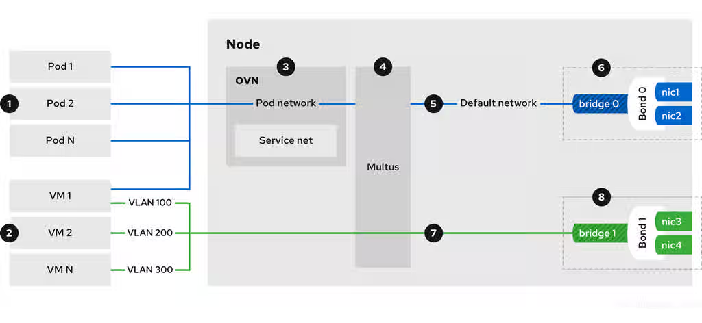
![]() Pods and VMs run on the same network infrastructure so you can easily connect your containerized and virtualized workloads.
Pods and VMs run on the same network infrastructure so you can easily connect your containerized and virtualized workloads.
![]() You can connect VMs to the default pod network and to any number of secondary networks.
You can connect VMs to the default pod network and to any number of secondary networks.
![]() The default pod network provides connectivity between all its members, service abstraction, IP management, micro segmentation, and other functionality.
The default pod network provides connectivity between all its members, service abstraction, IP management, micro segmentation, and other functionality.
![]() Multus is a "meta" CNI plugin that enables a pod or virtual machine to connect to additional network interfaces by using other compatible CNI plugins.
Multus is a "meta" CNI plugin that enables a pod or virtual machine to connect to additional network interfaces by using other compatible CNI plugins.
![]() The default pod network is overlay-based, tunneled through the underlying machine network.
The default pod network is overlay-based, tunneled through the underlying machine network.
![]() You can define the machine network over a selected set of network interface controllers (NICs).
You can define the machine network over a selected set of network interface controllers (NICs).
![]() Secondary VM networks are typically bridged directly to a physical network, with or without VLAN encapsulation. It is also possible to create virtual overlay networks for secondary networks.
Secondary VM networks are typically bridged directly to a physical network, with or without VLAN encapsulation. It is also possible to create virtual overlay networks for secondary networks.
Connecting VMs directly to the underlay network is not supported on Red Hat OpenShift Service on AWS, Azure,OpenShift Dedicated, Google Cloud, or Oracle® Cloud Infrastructure (OCI).
Connecting VMs to user-defined networks with the layer2 topology is recommended on public clouds.
![]() Secondary VM networks can be defined on dedicated set of NICs, as shown in figure 1, or they can use the machine network.
Secondary VM networks can be defined on dedicated set of NICs, as shown in figure 1, or they can use the machine network.
10.1.1. OpenShift Virtualization networking glossary
The following terms are used throughout OpenShift Virtualization documentation.
- Container Network Interface (CNI)
- A Content from www.cncf.io is not included.Cloud Native Computing Foundation project, focused on container network connectivity. OpenShift Virtualization uses CNI plugins to build upon the basic Kubernetes networking functionality.
- Multus
- A "meta" CNI plugin that allows multiple CNIs to exist so that a pod or virtual machine can use the interfaces it needs.
- Custom resource definition (CRD)
- A Content from kubernetes.io is not included.Kubernetes API resource that allows you to define custom resources, or an object defined by using the CRD API resource.
NetworkAttachmentDefinition- A CRD introduced by the Multus project that allows you to attach pods, virtual machines, and virtual machine instances to one or more networks.
UserDefinedNetwork- A namespace-scoped CRD introduced by the user-defined network (UDN) API that can be used to create a tenant network that isolates the tenant namespace from other namespaces.
ClusterUserDefinedNetwork- A cluster-scoped CRD introduced by the user-defined network API that cluster administrators can use to create a shared network across multiple namespaces.
NodeNetworkConfigurationPolicy-
A CRD introduced by the nmstate project, describing the requested network configuration on nodes. You update the node network configuration, including adding and removing interfaces, by applying a
NodeNetworkConfigurationPolicymanifest to the cluster.
10.1.2. Manage overlay networks
To ensure your virtual machines (VMs) connect reliably by using the standard OpenShift Container Platform networking model, configure the default pod network for cluster-wide connectivity.
Overlay networks provide a flexible, software-defined layer of connectivity on top of a physical network, enabling services like network segmentation, custom routing, and simplified management without altering the underlying hardware.
- Connect a VM to the default pod network
Each VM is connected by default to the default internal pod network. You can add or remove network interfaces by editing the VM specification.
You can access a virtual machine (VM) that is connected to the default internal pod network on a stable fully qualified domain name (FQDN) by using headless services.
- Connect a VM to a custom primary overlay network
Configure a primary user-defined network (UDN) that supports multi-namespace connectivity to provide isolated and flexible traffic paths for your workloads.
Cluster administrators can configure a primary
UserDefinedNetworkCRD to create a tenant network that isolates the tenant namespace from other namespaces without requiring network policies. Additionally, cluster administrators can use theClusterUserDefinedNetworkCRD to create a shared OVN layer 2 network across multiple namespaces.User-defined networks with the layer 2 overlay topology are useful for VM workloads, and a good alternative to secondary networks in environments where physical network access is limited, such as the public cloud. The layer 2 topology enables seamless migration of VMs without the need for Network Address Translation (NAT), and also provides persistent IP addresses that are preserved between reboots and during live migration.
- Connect a VM to a custom secondary overlay network
- Configure a secondary UDN with layer 2 topology to create a private isolated communication channel between a group of VMs across different nodes. A layer 2 topology connects workloads by a cluster-wide logical switch. The OVN-Kubernetes CNI plugin uses the Geneve (Generic Network Virtualization Encapsulation) protocol to create an overlay network between nodes. You can use this overlay network to connect VMs on different nodes, without having to configure any additional physical networking infrastructure.
- Configure external ingress by exposing a VM as a service
-
You can expose a VM within the cluster or outside the cluster by creating a
Serviceobject. For on-premise clusters, you can configure a load balancing service by using the MetalLB Operator. You can install the MetalLB Operator by using the OpenShift Container Platform web console or the CLI. - Add a VM to a Service Mesh
- OpenShift Virtualization is integrated with Red Hat OpenShift Service Mesh. You can monitor, visualize, and control traffic between pods and virtual machines on the default pod network with IPv4.
10.1.3. Connect to the provider’s physical network
To give virtual machines (VMs) access to the internet or other physical devices, you configure the node network, define the secondary network, and attach the VM to the secondary network.
- Connect a VM to the physical network by using an Open vSwitch bridge
You can connect a VM to the physical network infrastructure by configuring an OVN-Kubernetes secondary user-defined network (UDN) with the localnet topology.
A localnet topology connects the secondary network to the physical underlay. This enables both east-west cluster traffic and access to services running outside the cluster, but it requires additional configuration of the underlying Open vSwitch (OVS) bridge on cluster nodes.
Cluster administrators can use the following steps to configure the localnet UDN:
- Install the Kubernetes NMState Operator which provides a state-driven network configuration across cluster nodes.
-
Use the
NodeNetworkConfigurationPolicycustom resource (CR) to configure OVS bridges and add the appropriate bridge mappings on the nodes. -
Use the
ClusterUserDefinedNetworkCR from the UDN API to attach their workload to the underlay network through the OVS bridges configured in the previous step.
- Connect a VM to the physical network by using a Linux bridge
Install the Kubernetes NMState Operator to configure Linux bridges, VLANs, and bonding for your secondary networks. The OVN-Kubernetes
localnettopology is the recommended way of connecting a VM to the underlying physical network, but OpenShift Virtualization also supports Linux bridge networks.NoteYou cannot directly attach to the default machine network when using Linux bridge networks.
You can create a Linux bridge network and attach a VM to the network by performing the following steps:
- Prepare the node network by creating a Linux bridge node network configuration policy (NNCP).
- Define the secondary Linux bridge network by creating a network attachment definition (NAD).
- Attach the VM to the Linux bridge network.
- Connect a VM to the physical network by using an SR-IOV device
You can use Single Root I/O Virtualization (SR-IOV) network devices with additional networks on your OpenShift Container Platform cluster installed on bare metal or Red Hat OpenStack Platform (RHOSP) infrastructure for applications that require high bandwidth or low latency.
You must install the SR-IOV Network Operator on your cluster to manage SR-IOV network devices and network attachments.
You can connect a VM to an SR-IOV network by performing the following steps:
-
Configure an SR-IOV physical network device by creating a
SriovNetworkNodePolicyCR. -
Define the SR-IOV secondary network by creating an
SriovNetworkobject. - Connect the VM to the SR-IOV network by including the network details in the VM configuration.
-
Configure an SR-IOV physical network device by creating a
- Connect a VM to the physical network by using DPDK drivers with SR-IOV hardware
The Data Plane Development Kit (DPDK) provides a set of libraries and drivers for fast packet processing. You can configure clusters and VMs to run DPDK workloads over SR-IOV networks by performing the following steps:
- Configure the node hardware.
- Configure the VM namespace for DPDK.
- Configure the VM and guest OS to run DPDK applications.
10.1.3.1. Comparing Linux bridge CNI and OVN-Kubernetes localnet topology
The following table provides a comparison of features available when using the Linux bridge CNI compared to the localnet topology for an OVN-Kubernetes plugin.
Table 10.1. Linux bridge CNI compared to an OVN-Kubernetes localnet topology
| Feature | Available on Linux bridge CNI | Available on OVN-Kubernetes localnet |
|---|---|---|
| Layer 2 access to the underlay native network | Only on secondary network interface controllers (NICs) | Yes |
| Layer 2 access to underlay VLANs | Yes | Yes |
| Layer 2 trunk access | Yes | No |
| Network policies | No | Yes |
| MAC spoof filtering | Yes | Yes (Always on) |
10.1.4. Manage VM network interface configuration
Manage virtual machine (VM) network configuration to scale connectivity without incurring application downtime, troubleshoot network latency, define and automate management of MAC address pools, configure IP addresses, and isolate live migration traffic.
- Hot plug secondary network interfaces
- You can add or remove secondary network interfaces without stopping your VM. OpenShift Virtualization supports hot plugging and hot unplugging for secondary interfaces that use bridge binding and the VirtIO device driver. OpenShift Virtualization also supports hot plugging secondary interfaces that use the SR-IOV binding.
- Access a VM by using its external FQDN
-
You can access a virtual machine (VM) that is attached to a secondary network interface from outside the cluster by using its fully qualified domain name (FQDN). To connect to a VM by using its external FQDN, you must configure the DNS server, retrieve the cluster FQDN, and then connect to the VM by using the
sshcommand. - Manage the link state of a VM network interface
You can manage the link state of a primary or secondary VM network interface by using the OpenShift Container Platform web console or the command line. By specifying the link state, you can logically connect or disconnect the virtual network interface controller (vNIC) from a network.
NoteOpenShift Virtualization does not support link state management for Single Root I/O Virtualization (SR-IOV) secondary network interfaces and their link states are not reported.
- Configure and view VM IP address
- You can configure the IP address of a secondary network interface when you create a VM. The IP address is provisioned with cloud-init. You can view the IP address of a VM by using the OpenShift Container Platform web console or the command line. The network information is collected by the QEMU guest agent.
- Manage MAC address pools for VM network interfaces
- The KubeMacPool component allocates MAC addresses for VM network interfaces from a shared MAC address pool. This ensures that each network interface is assigned a unique MAC address. A virtual machine instance created from that VM retains the assigned MAC address across reboots.
- Configure a dedicated network for live migration
- You can configure a dedicated Multus network for live migration. A dedicated network minimizes the effects of network saturation on tenant workloads during live migration.
10.1.5. Configure VM SSH access
You can use SSH to securely access your virtual machines (VMs) from the command line.
To set up your SSH configuration, use one of the following methods:
- Use the
virtctl sshcommand You create an SSH key pair, add the public key to a VM, and connect to the VM by running the
virtctl sshcommand with the private key.You can add public SSH keys to Red Hat Enterprise Linux (RHEL) 9 VMs at runtime or at first boot to VMs with guest operating systems that can be configured by using a cloud-init data source.
- Use the
virtctl port-forwardcommand -
You add the
virtctl port-fowardcommand to your.ssh/configfile and connect to the VM by using OpenSSH. - Service
- You create a service, associate the service with the VM, and connect to the IP address and port exposed by the service.
- Secondary network
- You configure a secondary network, attach a VM to the secondary network interface, and connect to its allocated IP address.
10.1.6. Additional resources
- Connect a virtual machine to the default pod network
- Connect a virtual machine to a custom primary overlay network
- Connect a VM to a custom secondary overlay network
- Configure external ingress by exposing a VM as a service
- Add a VM to a Service Mesh
- Connect a VM to the physical network by using an Open vSwitch bridge
- Access a virtual machine by using its internal FQDN
- Installing the MetalLB Operator
- Connect a virtual machine to the physical network by using a Linux bridge
- Install the Kubernetes NMState Operator
- Connect a VM to the physical network by using an SR-IOV device
- Install the SR-IOV Network Operator
- Connect a VM to the physical network by using DPDK drivers with SR-IOV hardware
- Configure a dedicated network for live migration
- Access a VM by using its external FQDN
- Manage the link state of a virtual machine interface
- Hot plugging secondary network interfaces
- Configure and view VM IP address
- Manage MAC address pools for network interfaces
- SSH access for virtual machines
10.2. Connecting a virtual machine to the default pod network
You can connect a virtual machine to the default internal pod network by configuring its network interface to use the masquerade binding mode.
Traffic passing through network interfaces to the default pod network is interrupted during live migration.
10.2.1. Configuring masquerade mode from the CLI
You can use masquerade mode to hide a virtual machine’s outgoing traffic behind the pod IP address. Masquerade mode uses Network Address Translation (NAT) to connect virtual machines to the pod network backend through a Linux bridge.
Enable masquerade mode and allow traffic to enter the virtual machine by editing your virtual machine configuration file.
Prerequisites
-
You have installed the OpenShift CLI (
oc). - The virtual machine must be configured to use DHCP to acquire IPv4 addresses.
Procedure
Edit the
interfacesspec of your virtual machine configuration file:apiVersion: kubevirt.io/v1 kind: VirtualMachine metadata: name: example-vm spec: template: spec: domain: devices: interfaces: - name: default masquerade: {} ports: - port: 80 # ... networks: - name: default pod: {}-
spec.template.spec.domain.devices.interfaces.masqueradeconnects the virtual machine using masquerade mode. spec.template.spec.domain.devices.interfaces.portsis optional and defines the list of ports that you want to expose from the virtual machine, each specified by theportfield. Theportvalue must be a number between 0 and 65536. When theportsarray is not used, all ports in the valid range are open to incoming traffic. In this example, incoming traffic is allowed on port80.NotePorts 49152 and 49153 are reserved for use by the libvirt platform and all other incoming traffic to these ports is dropped.
-
Create the virtual machine:
$ oc create -f <vm-name>.yaml
10.2.2. Configuring masquerade mode with dual-stack (IPv4 and IPv6)
You can configure a new virtual machine (VM) to use both IPv6 and IPv4 on the default pod network by using cloud-init.
The Network.pod.vmIPv6NetworkCIDR field in the virtual machine instance configuration determines the static IPv6 address of the VM and the gateway IP address. These are used by the virt-launcher pod to route IPv6 traffic to the virtual machine and are not used externally. The Network.pod.vmIPv6NetworkCIDR field specifies an IPv6 address block in Classless Inter-Domain Routing (CIDR) notation. The default value is fd10:0:2::2/120. You can edit this value based on your network requirements.
When the virtual machine is running, incoming and outgoing traffic for the virtual machine is routed to both the IPv4 address and the unique IPv6 address of the virt-launcher pod. The virt-launcher pod then routes the IPv4 traffic to the DHCP address of the virtual machine, and the IPv6 traffic to the statically set IPv6 address of the virtual machine.
Prerequisites
- The OpenShift Container Platform cluster must use the OVN-Kubernetes Container Network Interface (CNI) network plugin configured for dual-stack.
-
You have installed the OpenShift CLI (
oc).
Procedure
In a new virtual machine configuration, include an interface with
masqueradeand configure the IPv6 address and default gateway by using cloud-init.apiVersion: kubevirt.io/v1 kind: VirtualMachine metadata: name: example-vm-ipv6 spec: template: spec: domain: devices: interfaces: - name: default masquerade: {} ports: - port: 80 # ... networks: - name: default pod: {} volumes: - cloudInitNoCloud: networkData: | version: 2 ethernets: eth0: dhcp4: true addresses: [ fd10:0:2::2/120 ] gateway6: fd10:0:2::1-
spec.template.spec.domain.devices.interfaces.masqueradeconnects the virtual machine using masquerade mode. -
spec.template.spec.domain.devices.interfaces.ports.portallows incoming traffic on port 80 to the virtual machine. -
spec.template.spec.volumes.cloudInitNoCloud.networkData.ethernets.eth0.addressesdefines the static IPv6 address as determined by theNetwork.pod.vmIPv6NetworkCIDRfield in the virtual machine instance configuration. The default value isfd10:0:2::2/120. -
spec.template.spec.volumes.cloudInitNoCloud.networkData.ethernets.eth0.gateway6defines the gateway IP address as determined by theNetwork.pod.vmIPv6NetworkCIDRfield in the virtual machine instance configuration. The default value isfd10:0:2::1.
-
Create the virtual machine in the namespace:
$ oc create -f example-vm-ipv6.yaml
Verification
- To verify that IPv6 has been configured, start the virtual machine and view the interface status of the virtual machine instance to ensure it has an IPv6 address:
$ oc get vmi <vmi-name> -o jsonpath="{.status.interfaces[*].ipAddresses}"10.2.3. About jumbo frames support
When using the OVN-Kubernetes CNI plugin, you can send unfragmented jumbo frame packets between two virtual machines (VMs) that are connected on the default pod network. Jumbo frames have a maximum transmission unit (MTU) value greater than 1500 bytes.
The VM automatically gets the MTU value of the cluster network, set by the cluster administrator, in one of the following ways:
-
libvirt: If the guest OS has the latest version of the VirtIO driver that can interpret incoming data via a Peripheral Component Interconnect (PCI) config register in the emulated device. - DHCP: If the guest DHCP client can read the MTU value from the DHCP server response.
For Windows VMs that do not have a VirtIO driver, you must set the MTU manually by using netsh or a similar tool. This is because the Windows DHCP client does not read the MTU value.
10.2.4. Additional resources
10.3. Connecting a virtual machine to a primary user-defined network
You can connect a virtual machine (VM) to a user-defined network (UDN) on the VM’s primary interface by using the OpenShift Container Platform web console or the CLI. The primary user-defined network replaces the default pod network in your specified namespace. Unlike the pod network, you can define the primary UDN per project, where each project can use its specific subnet and topology.
OpenShift Virtualization supports the namespace-scoped UserDefinedNetwork and the cluster-scoped ClusterUserDefinedNetwork custom resource definitions (CRD).
Cluster administrators can configure a primary UserDefinedNetwork CRD to create a tenant network that isolates the tenant namespace from other namespaces without requiring network policies. Additionally, cluster administrators can use the ClusterUserDefinedNetwork CRD to create a shared OVN network across multiple namespaces.
You must add the k8s.ovn.org/primary-user-defined-network label when you create a namespace that is to be used with user-defined networks.
With the layer 2 topology, OVN-Kubernetes creates an overlay network between nodes. You can use this overlay network to connect VMs on different nodes without having to configure any additional physical networking infrastructure.
The layer 2 topology enables seamless migration of VMs without the need for Network Address Translation (NAT) because persistent IP addresses are preserved across cluster nodes during live migration.
You must consider the following limitations before implementing a primary UDN:
-
You cannot use the
virtctl sshcommand to configure SSH access to a VM. -
You cannot use the
oc port-forwardcommand to forward ports to a VM. - You cannot use headless services to access a VM.
10.3.1. Create a primary user-defined network by using the web console
You can use the OpenShift Container Platform web console to create a primary namespace-scoped UserDefinedNetwork or a cluster-scoped ClusterUserDefinedNetwork custom resource definition (CRD). The UDN serves as the default primary network for pods and VMs that you create in namespaces associated with the network.
After you define the custom primary overlay network, you can create namespaces that are associated with the cluster-scoped UDN.
10.3.1.1. Creating a namespace for user-defined networks by using the web console
You can create a namespace to be used with primary user-defined networks (UDNs) by using the OpenShift Container Platform web console.
Prerequisites
-
Log in to the OpenShift Container Platform web console as a user with
cluster-adminpermissions.
Procedure
- From the Administrator perspective, click Administration → Namespaces.
- Click Create Namespace.
- In the Name field, specify a name for the namespace. The name must consist of lower case alphanumeric characters or '-', and must start and end with an alphanumeric character.
-
In the Labels field, add the
k8s.ovn.org/primary-user-defined-networklabel. -
Optional: If the namespace is to be used with an existing cluster-scoped UDN, add the appropriate labels as defined in the
spec.namespaceSelectorfield in theClusterUserDefinedNetworkcustom resource. - Optional: Specify a default network policy.
- Click Create to create the namespace.
10.3.1.2. Creating a primary namespace-scoped user-defined network by using the web console
You can create an isolated primary network in your project namespace by creating a UserDefinedNetwork custom resource in the OpenShift Container Platform web console.
Prerequisites
-
You have access to the OpenShift Container Platform web console as a user with
cluster-adminpermissions. -
You have created a namespace and applied the
k8s.ovn.org/primary-user-defined-networklabel. For more information, see "Creating a namespace for user-defined networks by using the web console".
Procedure
- From the Administrator perspective, click Networking → UserDefinedNetworks.
- Click Create UserDefinedNetwork.
- From the Project name list, select the namespace that you previously created.
- Specify a value in the Subnet field.
- Click Create. The user-defined network serves as the default primary network for pods and virtual machines that you create in this namespace.
10.3.1.3. Creating a cluster-scoped network to connect pods directly to an external network
You can connect one or more projects to a physical network for direct layer 2 access to data center resources through a ClusterUserDefinedNetwork custom resource in the OpenShift Container Platform web console.
Prerequisites
-
You have access to the OpenShift Container Platform web console as a user with
cluster-adminpermissions.
Procedure
- In the OpenShift Container Platform web console, go to Virtualization → Networking.
- Click Virtual machine networks in the navigation pane.
- Click Create. The Create virtual machine network wizard is displayed.
Give details about the network on the Network definition page:
- Enter a name for the network in the Name field.
-
Select a physical network through an
OpenvSwitchbridge from the Select physical network list. Enter the maximum transmission unit (MTU).
NoteAn MTU, measured in bytes, is the largest allowable size of a data packet. Ensure that all underlying physical network equipment supports this MTU, or higher.
- Optional: Select the VLAN ID checkbox to enter VLAN tagging information. If you tag traffic with a VLAN ID, you must configure your physical switch with a VLAN trunk that includes the VLAN ID that you choose.
- Click Next.
- Select the projects that the network should be made available to on the Project mapping page. By default, all projects have access to the network.
- Click Create.
Verification
- Navigate to the Virtualization → Virtual machine networks page.
- Click the OVN localnet tab.
- Verify that your new network is displayed in the list.
10.3.1.4. Creating a primary cluster-scoped user-defined network by using the web console
You can connect multiple namespaces to the same primary user-defined network (UDN) by creating a ClusterUserDefinedNetwork custom resource in the OpenShift Container Platform web console.
Prerequisites
-
You have access to the OpenShift Container Platform web console as a user with
cluster-adminpermissions.
Procedure
- From the Administrator perspective, click Networking → UserDefinedNetworks.
- From the Create list, select ClusterUserDefinedNetwork.
- In the Name field, specify a name for the cluster-scoped UDN.
- Specify a value in the Subnet field.
- In the Project(s) Match Labels field, add the appropriate labels to select namespaces that the cluster UDN applies to.
- Click Create. The cluster-scoped UDN serves as the default primary network for pods and virtual machines located in namespaces that contain the labels that you specified in step 5.
10.3.2. Create a primary user-defined network by using the CLI
You can create a primary UserDefinedNetwork or ClusterUserDefinedNetwork custom resource definition (CRD) by using the OpenShift CLI (oc). After you define the custom primary overlay network, you can create namespaces that are associated with the cluster-scoped UDN.
10.3.2.1. Creating a namespace for user-defined networks by using the CLI
You can create a namespace to be used with primary user-defined networks (UDNs) by using the OpenShift CLI (oc).
Prerequisites
-
You have access to the cluster as a user with
cluster-adminpermissions. -
You have installed the OpenShift CLI (
oc).
Procedure
Create a
Namespaceobject as a YAML file similar to the following example:apiVersion: v1 kind: Namespace metadata: name: my-namespace labels: k8s.ovn.org/primary-user-defined-network: "" # ...The
k8s.ovn.org/primary-user-defined-networklabel is required for the namespace to be associated with a UDN. If the namespace is to be used with an existing cluster UDN, you must also add the appropriate labels that are defined in thespec.namespaceSelectorfield of theClusterUserDefinedNetworkcustom resource.Apply the
Namespacemanifest by running the following command:$ oc apply -f <filename>.yaml
10.3.2.2. Creating a primary namespace-scoped user-defined network by using the CLI
You can create an isolated primary network in your project namespace by using the CLI. You must use the OVN-Kubernetes layer 2 topology and enable persistent IP address allocation in the user-defined network (UDN) configuration to ensure VM live migration support.
Prerequisites
-
You have installed the OpenShift CLI (
oc). -
You have created a namespace and applied the
k8s.ovn.org/primary-user-defined-networklabel.
Procedure
Create a
UserDefinedNetworkobject to specify the custom network configuration.Example
UserDefinedNetworkmanifest:apiVersion: k8s.ovn.org/v1 kind: UserDefinedNetwork metadata: name: udn-l2-net namespace: my-namespace spec: topology: Layer2 layer2: role: Primary subnets: - "10.0.0.0/24" - "2001:db8::/60" ipam: lifecycle: Persistent-
metadata.namespecifies the name of theUserDefinedNetworkcustom resource. -
metadata.namespacespecifies the namespace in which the VM is located. The namespace must have thek8s.ovn.org/primary-user-defined-networklabel. The namespace must not bedefault, anopenshift-*namespace, or match any global namespaces that are defined by the Cluster Network Operator (CNO). -
spec.topologyspecifies the topological configuration of the network. The required value isLayer2. ALayer2topology creates a logical switch that is shared by all nodes. -
spec.layer2.rolespecifies whether the UDN is primary or secondary. ThePrimaryrole means that the UDN acts as the primary network for the VM and all default traffic passes through this network. -
spec.layer2.ipam.lifecyclespecifies that virtual workloads have consistent IP addresses across reboots and migration. Thespec.layer2.subnetsfield is required whenipam.lifecycle: Persistentis specified.
-
Apply the
UserDefinedNetworkmanifest by running the following command:$ oc apply -f --validate=true <filename>.yaml
10.3.2.3. Creating a primary cluster-scoped user-defined network by using the CLI
You can connect multiple namespaces to the same primary user-defined network (UDN) to achieve native tenant isolation by using the CLI.
Prerequisites
-
You have access to the cluster as a user with
cluster-adminprivileges. -
You have installed the OpenShift CLI (
oc).
Procedure
Create a
ClusterUserDefinedNetworkobject to specify the custom network configuration.Example
ClusterUserDefinedNetworkmanifest:apiVersion: k8s.ovn.org/v1 kind: ClusterUserDefinedNetwork metadata: name: cudn-l2-net spec: namespaceSelector: matchExpressions: - key: kubernetes.io/metadata.name operator: In values: ["red-namespace", "blue-namespace"] network: topology: Layer2 layer2: role: Primary ipam: lifecycle: Persistent subnets: - 203.203.0.0/16-
metadata.namespecifies the name of theClusterUserDefinedNetworkcustom resource. -
spec.namespaceSelectorspecifies the set of namespaces that the cluster UDN applies to. The namespace selector must not point todefault, anopenshift-*namespace, or any global namespaces that are defined by the Cluster Network Operator (CNO). -
spec.namespaceSelector.matchExpressionsspecifies the type of selector. In this example, thematchExpressionsselector selects objects that have the labelkubernetes.io/metadata.namewith the valuered-namespaceorblue-namespace. -
spec.namespaceSelector.matchExpressions.operatorspecifies the type of operator. Possible values areIn,NotIn, andExists. -
spec.network.topologyspecifies the topological configuration of the network. The required value isLayer2. ALayer2topology creates a logical switch that is shared by all nodes. -
spec.network.layer2.rolespecifies whether the UDN is primary or secondary. ThePrimaryrole means that the UDN acts as the primary network for the VM and all default traffic passes through this network.
-
Apply the
ClusterUserDefinedNetworkmanifest by running the following command:$ oc apply -f --validate=true <filename>.yaml
10.3.3. Attach a virtual machine to the primary user-defined network
You can connect a virtual machine (VM) to the primary user-defined network (UDN) by requesting the pod network attachment and configuring the interface binding.
OpenShift Virtualization supports the following network binding plugins to connect the network interface to the VM:
- Layer 2 bridge
- The Layer 2 bridge binding creates a direct Layer 2 connection between the VM’s virtual interface and the virtual switch of the UDN.
- Passt
The Plug a Simple Socket Transport (passt) binding provides a user-space networking solution that integrates seamlessly with the pod network, providing better integration with the OpenShift Container Platform networking ecosystem.
Passt binding has the following benefits:
- You can define readiness and liveness HTTP probes to configure VM health checks.
- You can use Red Hat Advanced Cluster Security to monitor TCP traffic within the cluster with detailed insights.
Using the passt binding plugin to attach a VM to the primary UDN is a Technology Preview feature only. Technology Preview features are not supported with Red Hat production service level agreements (SLAs) and might not be functionally complete. Red Hat does not recommend using them in production. These features provide early access to upcoming product features, enabling customers to test functionality and provide feedback during the development process.
For more information about the support scope of Red Hat Technology Preview features, see Technology Preview Features Support Scope.
10.3.3.1. Attaching a virtual machine to the primary user-defined network by using the web console
You can connect a virtual machine (VM) to the primary user-defined network (UDN) by using the OpenShift Container Platform web console. VMs that are created in a namespace where the primary UDN is configured are automatically attached to the UDN with the Layer 2 bridge network binding plugin.
To attach a VM to the primary UDN by using the Plug a Simple Socket Transport (passt) binding, enable the plugin and configure the VM network interface in the web console.
Using the passt binding plugin to attach a VM to the primary UDN is a Technology Preview feature only. Technology Preview features are not supported with Red Hat production service level agreements (SLAs) and might not be functionally complete. Red Hat does not recommend using them in production. These features provide early access to upcoming product features, enabling customers to test functionality and provide feedback during the development process.
For more information about the support scope of Red Hat Technology Preview features, see Technology Preview Features Support Scope.
Prerequisites
- You are logged in to the OpenShift Container Platform web console.
Procedure
Follow these steps to enable the passt network binding plugin Technology Preview feature:
- From the Virtualization perspective, click Overview.
- On the Virtualization page, click the Settings tab.
- Click Preview features and set Enable Passt binding for primary user-defined networks to on.
- From the Virtualization perspective, click VirtualMachines.
- Select a VM to open the VirtualMachine details page.
- Click the Configuration tab.
- Click Network.
-
Click the Options menu
on the Network interfaces page and select Edit.
- In the Edit network interface dialog, select the default pod network attachment from the Network list.
- Expand Advanced and then select the Passt binding.
- Click Save.
- If your VM is running, restart it for the changes to take effect.
10.3.3.2. Attaching a virtual machine to the primary user-defined network by using the CLI
You can connect a virtual machine (VM) to the primary user-defined network (UDN) by using the OpenShift CLI (oc).
Using the passt binding plugin to attach a VM to the primary UDN is a Technology Preview feature only. Technology Preview features are not supported with Red Hat production service level agreements (SLAs) and might not be functionally complete. Red Hat does not recommend using them in production. These features provide early access to upcoming product features, enabling customers to test functionality and provide feedback during the development process.
For more information about the support scope of Red Hat Technology Preview features, see Technology Preview Features Support Scope.
Prerequisites
-
You have installed the OpenShift CLI (
oc).
Procedure
Edit the
VirtualMachinemanifest to add the UDN interface details, as in the following example:Example
VirtualMachinemanifest:apiVersion: kubevirt.io/v1 kind: VirtualMachine metadata: name: example-vm namespace: my-namespace spec: template: spec: domain: devices: interfaces: - name: udn-l2-net binding: name: l2bridge # ... networks: - name: udn-l2-net pod: {} # ...-
metadata.namespacespecifies the namespace in which the VM is located. This value must match the namespace in which the UDN is defined. -
spec.template.spec.domain.devices.interfaces.namespecifies the name of the user-defined network interface. -
spec.template.spec.domain.devices.interfaces.binding.namespecifies the name of the binding plugin that is used to connect the interface to the VM. The possible values arel2bridgeandpasst. The default value isl2bridge. -
spec.template.spec.networks.namespecifies the name of the network. This must match the value of thespec.template.spec.domain.devices.interfaces.namefield.
-
Optional: If you are using the Plug a Simple Socket Transport (passt) network binding plugin, set the
hco.kubevirt.io/deployPasstNetworkBindingannotation totruein theHyperConvergedcustom resource (CR) by running the following command:$ oc annotate hco kubevirt-hyperconverged -n kubevirt-hyperconverged hco.kubevirt.io/deployPasstNetworkBinding=true --overwrite
Apply the
VirtualMachinemanifest by running the following command:$ oc apply -f <filename>.yaml
10.3.4. Additional resources
10.4. Connecting a virtual machine to a secondary localnet user-defined network
You can connect a virtual machine (VM) to an OVN-Kubernetes localnet secondary network by using the CLI. Cluster administrators can use the ClusterUserDefinedNetwork (CUDN) custom resource definition (CRD) to create a shared OVN-Kubernetes network across multiple namespaces.
An OVN-Kubernetes secondary network is compatible with the multi-network policy API which provides the MultiNetworkPolicy custom resource definition (CRD) to control traffic flow to and from VMs. For more information, see "Additional resources".
You must use the ipBlock attribute to define network policy ingress and egress rules for specific CIDR blocks. Using pod or namespace selector policy peers is not supported.
A localnet topology connects the secondary network to the physical underlay. This enables both east-west cluster traffic and access to services running outside the cluster, but it requires additional configuration of the underlying Open vSwitch (OVS) system on cluster nodes.
10.4.1. Creating a user-defined-network for localnet topology by using the CLI
You can create a secondary cluster-scoped user-defined-network (CUDN) for the localnet network topology by using the CLI.
Prerequisites
-
You are logged in to the cluster as a user with
cluster-adminprivileges. -
You have installed the OpenShift CLI (
oc). - You installed the Kubernetes NMState Operator.
Procedure
Create a
NodeNetworkConfigurationPolicyobject to map the OVN-Kubernetes secondary network to an Open vSwitch (OVS) bridge.Example
NodeNetworkConfigurationPolicymanifest:apiVersion: nmstate.io/v1 kind: NodeNetworkConfigurationPolicy metadata: name: mapping spec: nodeSelector: node-role.kubernetes.io/worker: '' desiredState: ovn: bridge-mappings: - localnet: localnet1 bridge: br-ex state: present-
metadata.namespecifies the name of the configuration object. -
spec.nodeSelectorspecifies the nodes to which the node network configuration policy is applied. The recommended node selector value isnode-role.kubernetes.io/worker: ''. -
spec.desiredState.ovn.bridge-mappings.localnetspecifies the name of the additional network from which traffic is forwarded to the OVS bridge. This attribute must match the value of thespec.network.localnet.physicalNetworkNamefield of theClusterUserDefinedNetworkobject that defines the OVN-Kubernetes additional network. This example uses the namelocalnet1. -
spec.desiredState.ovn.bridge-mappings.bridgespecifies name of the OVS bridge on the node. This value is required if thestateattribute ispresentor not specified. spec.desiredState.ovn.bridge-mappings.statespecifies the state of the mapping. Must be eitherpresentto add the mapping orabsentto remove the mapping. The default value ispresent.ImportantOpenShift Virtualization does not support Linux bridge bonding modes 0, 5, and 6. For more information, see Which bonding modes work when used with a bridge that virtual machine guests or containers connect to?.
-
Apply the
NodeNetworkConfigurationPolicymanifest by running the following command:$ oc apply -f <filename>.yaml
where:
<filename>-
Specifies the name of your
NodeNetworkConfigurationPolicymanifest YAML file.
Create a
ClusterUserDefinedNetworkobject to create a localnet secondary network.Example
ClusterUserDefinedNetworkmanifest:apiVersion: k8s.ovn.org/v1 kind: ClusterUserDefinedNetwork metadata: name: cudn-localnet spec: namespaceSelector: matchExpressions: - key: kubernetes.io/metadata.name operator: In values: ["red", "blue"] network: topology: Localnet localnet: role: Secondary physicalNetworkName: localnet1 ipam: mode: Disabled # ...-
metadata.namespecifies the name of theClusterUserDefinedNetworkcustom resource. -
spec.namespaceSelectorspecifies a set of namespaces that the cluster UDN applies to. The namespace selector must not point to the following values:default; anopenshift-*namespace; or any global namespaces that are defined by the Cluster Network Operator (CNO). -
spec.namespaceSelector.matchExpressionsspecifies the type of selector. In this example, thematchExpressionsselector selects objects that have the labelkubernetes.io/metadata.namewith the valueredorblue. -
spec.namespaceSelector.matchExpressions.operatorspecifies the type of operator. Possible values areIn,NotIn, andExists. -
spec.network.topologyspecifies the topological configuration of the network. ALocalnettopology connects the logical network to the physical underlay. -
spec.network.localnet.rolespecifies whether the UDN is primary or secondary. The required value isSecondaryfortopology: Localnet. -
spec.network.localnet.physicalNetworkNamespecifies the name of the OVN-Kubernetes bridge mapping that is configured on the node. This value must match thespec.desiredState.ovn.bridge-mappings.localnetfield in theNodeNetworkConfigurationPolicymanifest that you previously created. This ensures that you are bridging to the intended segment of your physical network. -
spec.network.localnet.ipam.modespecifies whether IP address management (IPAM) is enabled or disabled. The required value isDisabled. OpenShift Virtualization does not support configuring IPAM for virtual machines.
-
Apply the
ClusterUserDefinedNetworkmanifest by running the following command:$ oc apply -f <filename>.yaml
where:
<filename>-
Specifies the name of your
ClusterUserDefinedNetworkmanifest YAML file.
10.4.2. Creating a namespace for secondary user-defined networks by using the CLI
You can create a namespace to be used with an existing secondary cluster-scoped user-defined network (CUDN) by using the CLI.
Prerequisites
-
You are logged in to the cluster as a user with
cluster-adminpermissions. -
You have installed the OpenShift CLI (
oc).
Procedure
Create a
Namespaceobject similar to the following example:apiVersion: v1 kind: Namespace metadata: name: red # ...
Apply the
Namespacemanifest by running the following command:oc apply -f <filename>.yaml
where:
<filename>-
Specifies the name of your
Namespacemanifest YAML file.
10.4.3. Attaching a virtual machine to secondary user-defined networks by using the CLI
You can connect a virtual machine (VM) to multiple secondary cluster-scoped user-defined networks (CUDNs) by configuring the interface binding.
Prerequisites
-
You have installed the OpenShift CLI (
oc).
Procedure
Edit the
VirtualMachinemanifest to add the CUDN interface details, as in the following example:apiVersion: kubevirt.io/v1 kind: VirtualMachine metadata: name: example-vm namespace: red spec: template: spec: domain: devices: interfaces: - name: secondary_localnet bridge: {} machine: type: "" resources: requests: memory: 2048M networks: - name: secondary_localnet multus: networkName: <localnet_cudn_name>-
metadata.namespacespecifies the namespace in which the VM is located. This value must match a namespace that is associated with the secondary CUDN. -
spec.template.spec.domain.devices.interfaces.namespecifies the name of the secondary user-defined network interface. -
spec.template.spec.networks.namespecifies the name of the network. This value must match the value of thespec.template.spec.domain.devices.interfaces.namefield. -
spec.template.spec.networks.multus.networkNamespecifies the name of the localnetClusterUserDefinedNetworkobject that you previously created.
-
Apply the
VirtualMachinemanifest by running the following command:$ oc apply -f <filename>.yaml
where:
<filename>Specifies the name of your
VirtualMachinemanifest YAML file.NoteWhen running OpenShift Virtualization on IBM Z®, be aware that certain network interfaces, such as OSA, RoCE, and HiperSockets, only forward network traffic to devices that are registered with the respective interface. As a result, any traffic that is destined for unregistered devices is not forwarded.
10.4.4. Additional resources
10.5. Exposing a virtual machine by using a service
You can expose a virtual machine (VM) within the cluster or outside the cluster by creating a Service object. By exposing a VM as a Kubernetes service, you can leverage native load balancing and observability tools that provide unified traffic management, consistent SSL termination, and centralized security policies across hybrid workloads.
10.5.1. About services
A Kubernetes service exposes network access for clients to an application running on a set of pods. Services offer abstraction, load balancing, and, in the case of the NodePort and LoadBalancer types, exposure to the outside world.
ClusterIP-
Exposes the service on an internal IP address and as a DNS name to other applications within the cluster. A single service can map to multiple virtual machines. When a client tries to connect to the service, the client’s request is load balanced among available backends.
ClusterIPis the default service type. NodePort-
Exposes the service on the same port of each selected node in the cluster.
NodePortmakes a port accessible from outside the cluster, provided that the node itself is externally accessible to the client. LoadBalancer- Creates an external load balancer in the current cloud (if supported) and assigns a fixed, external IP address to the service.
For on-premise clusters, you can configure a load balancing service by deploying the MetalLB Operator.
10.5.2. Dual-stack support
If IPv4 and IPv6 dual-stack networking is enabled for your cluster, you can create a service that uses IPv4, IPv6, or both, by defining the spec.ipFamilyPolicy and the spec.ipFamilies fields in the Service object.
The spec.ipFamilyPolicy field can be set to one of the following values:
- SingleStack
- The control plane assigns a cluster IP address for the service based on the first configured service cluster IP range.
- PreferDualStack
- The control plane assigns both IPv4 and IPv6 cluster IP addresses for the service on clusters that have dual-stack configured.
- RequireDualStack
-
This option fails for clusters that do not have dual-stack networking enabled. For clusters that have dual-stack configured, the behavior is the same as when the value is set to
PreferDualStack. The control plane allocates cluster IP addresses from both IPv4 and IPv6 address ranges.
You can define which IP family to use for single-stack or define the order of IP families for dual-stack by setting the spec.ipFamilies field to one of the following array values:
-
[IPv4] -
[IPv6] -
[IPv4, IPv6] -
[IPv6, IPv4]
IPv6 single stack and the [IPv6, IPv4] array are not supported in IBM Z® and IBM® LinuxONE.
10.5.3. Creating a service by using the CLI
You can create a service and associate it with a virtual machine (VM) by using the command line.
Prerequisites
- You configured the cluster network to support the service.
-
You have installed the OpenShift CLI (
oc).
Procedure
Edit the
VirtualMachinemanifest to add the label for service creation. Addspecial: keyto thespec.template.metadata.labelsstanza:apiVersion: kubevirt.io/v1 kind: VirtualMachine metadata: name: example-vm namespace: example-namespace spec: runStrategy: Halted template: metadata: labels: special: key # ...NoteLabels on a virtual machine pass through to the pod. The
special: keylabel must match the label in thespec.selectorattribute of theServicemanifest.-
Save the
VirtualMachinemanifest file to apply your changes. Create a
Servicemanifest to expose the VM:apiVersion: v1 kind: Service metadata: name: example-service namespace: example-namespace spec: # ... selector: special: key type: NodePort ports: protocol: TCP port: 80 targetPort: 9376 nodePort: 30000-
spec.selectordefines the label that you added to thespec.template.metadata.labelsstanza of theVirtualMachinemanifest. -
spec.typedefines the type of service by the way it is exposed. Choose one ofClusterIP,NodePort, orLoadBalancer. -
spec.portsdefines a collection of network ports and protocols to expose from the virtual machine.
-
-
Save the
Servicemanifest file. Create the service by running the following command:
$ oc create -f example-service.yaml
- Restart the VM to apply the changes.
Verification
Query the
Serviceobject to verify that it is available:$ oc get service -n example-namespace
10.5.4. Additional resources
10.6. Accessing a virtual machine by using its internal FQDN
You can access a virtual machine (VM) that is connected to the default internal pod network on a stable fully qualified domain name (FQDN) by using headless services. A Kubernetes headless service creates a DNS record for each pod associated with the service instead of providing a single virtual IP address for the service. You can expose a VM through its FQDN without having to expose a specific TCP or UDP port.
If you created a VM by using the OpenShift Container Platform web console, you can find its internal FQDN listed in the Network tile on the Overview tab of the VirtualMachine details page.
10.6.1. Creating a headless service in a project by using the CLI
To create a headless service in a namespace, add the clusterIP: None parameter to the service YAML definition.
Prerequisites
-
You have installed the OpenShift CLI (
oc).
Procedure
Create a
Servicemanifest to expose the VM, such as the following example:apiVersion: v1 kind: Service metadata: name: mysubdomain spec: selector: expose: me clusterIP: None ports: - protocol: TCP port: 1234 targetPort: 1234-
metadata.namedefines the name of the service. This must match thespec.subdomainattribute in theVirtualMachinemanifest file. -
spec.selectordefines the service selector that must match theexpose:melabel in theVirtualMachinemanifest file. -
spec.clusterIPdefines a headless service. -
spec.portsdefines the list of ports that are exposed by the service. You must define at least one port. This can be any arbitrary value as it does not affect the headless service.
-
-
Save the
Servicemanifest file. Create the service by running the following command:
$ oc create -f headless_service.yaml
10.6.2. Mapping a virtual machine to a headless service by using the CLI
To connect to a virtual machine (VM) from within the cluster by using its internal fully qualified domain name (FQDN), you must first map the VM to a headless service. Set the spec.hostname and spec.subdomain parameters in the VM configuration file.
If a headless service exists with a name that matches the subdomain, a unique DNS A record is created for the VM in the form of <vm.spec.hostname>.<vm.spec.subdomain>.<vm.metadata.namespace>.svc.cluster.local.
Prerequisites
-
You have installed the OpenShift CLI (
oc).
Procedure
Edit the
VirtualMachinemanifest to add the service selector label and subdomain by running the following command:$ oc edit vm <vm_name>
Example
VirtualMachinemanifest file:apiVersion: kubevirt.io/v1 kind: VirtualMachine metadata: name: vm-fedora spec: template: metadata: labels: expose: me spec: hostname: "myvm" subdomain: "mysubdomain" # ...-
spec.template.metadata.labels.exposedefines a label that must match thespec.selectorattribute of theServicemanifest that you previously created. -
spec.template.spec.hostnamedefines the hostname. If this attribute is not specified, the resulting DNS A record takes the form of<vm.metadata.name>.<vm.spec.subdomain>.<vm.metadata.namespace>.svc.cluster.local. -
spec.template.spec.subdomaindefines the subdomain. Thespec.subdomainattribute must match themetadata.namevalue of theServiceobject.
-
- Save your changes and exit the editor.
- Restart the VM to apply the changes.
10.6.3. Connecting to a virtual machine by using its internal FQDN
You can connect to a virtual machine (VM) by using its internal fully qualified domain name (FQDN).
Prerequisites
-
You have installed the
virtctltool. -
You have identified the internal FQDN of the VM from the web console or by mapping the VM to a headless service. The internal FQDN has the format
<vm.spec.hostname>.<vm.spec.subdomain>.<vm.metadata.namespace>.svc.cluster.local.
Procedure
Connect to the VM console by entering the following command:
$ virtctl console vm-fedora
To connect to the VM by using the requested FQDN, run the following command:
$ ping myvm.mysubdomain.<namespace>.svc.cluster.local
Example output:
PING myvm.mysubdomain.default.svc.cluster.local (10.244.0.57) 56(84) bytes of data. 64 bytes from myvm.mysubdomain.default.svc.cluster.local (10.244.0.57): icmp_seq=1 ttl=64 time=0.029 ms
In the preceding example, the DNS entry for
myvm.mysubdomain.default.svc.cluster.localpoints to10.244.0.57, which is the cluster IP address that is currently assigned to the VM.
10.6.4. Additional resources
10.7. Connecting a virtual machine to a Linux bridge network
By default, OpenShift Virtualization is installed with a single, internal pod network. You can connect a virtual machine (VM) to the physical network by using a Linux bridge.
To create a Linux bridge network and attach a VM to the network, perform the following steps:
- Prepare the node network by creating a Linux bridge node network configuration policy (NNCP).
- Define the secondary Linux bridge network by creating a network attachment definition (NAD).
- Attach the VM to the Linux bridge network.
OpenShift Virtualization does not support Linux bridge bonding modes 0, 5, and 6. For more information, see "Additional resources".
10.7.1. Creating a Linux bridge NNCP
After you install the Kubernetes NMState Operator, you can configure a Linux bridge network for live migration or external access to virtual machines (VMs).
You can create a NodeNetworkConfigurationPolicy (NNCP) manifest for a Linux bridge network.
Prerequisites
- You have installed the Kubernetes NMState Operator.
Procedure
Create the
NodeNetworkConfigurationPolicymanifest. This example includes sample values that you must replace with your own information.apiVersion: nmstate.io/v1 kind: NodeNetworkConfigurationPolicy metadata: name: br1-eth1-policy spec: desiredState: interfaces: - name: br1 description: Linux bridge with eth1 as a port type: linux-bridge state: up ipv4: enabled: false bridge: options: stp: enabled: false port: - name: eth1-
metadata.namedefines the name of the node network configuration policy. -
spec.desiredState.interfaces.namedefines the name of the new Linux bridge. -
spec.desiredState.interfaces.descriptionis an optional field that can be used to define a human-readable description for the bridge. -
spec.desiredState.interfaces.typedefines the interface type. In this example, the type is a Linux bridge. -
spec.desiredState.interfaces.statedefines the requested state for the interface after creation. -
spec.desiredState.interfaces.ipv4.enableddefines whether the ipv4 protocol is active. Setting this tofalsedisables IPv4 addressing on this bridge. -
spec.desiredState.interfaces.bridge.options.stp.enableddefines whether Spanning Tree Protocol (STP) is active. Setting this tofalsedisables STP on this bridge. spec.desiredState.interfaces.bridge.port.namedefines the node NIC that the bridge is attached to.NoteTo create the NNCP manifest for a Linux bridge using Open Systems Adapter (OSA) with IBM Z®, you must disable VLAN filtering by the setting the
rx-vlan-filtertofalsein theNodeNetworkConfigurationPolicymanifest.Alternatively, if you have SSH access to the node, you can disable VLAN filtering by running the following command:
$ sudo ethtool -K <osa-interface-name> rx-vlan-filter off
-
10.7.2. Creating a Linux bridge NAD by using the web console
Use the OpenShift Container Platform web console to create a network attachment definition (NAD) that connects pods and virtual machines to a layer-2 network.
Configuring IP address management (IPAM) in a network attachment definition for virtual machines is not supported.
Procedure
- In the web console, click Networking → NetworkAttachmentDefinitions.
Click Create Network Attachment Definition.
NoteThe network attachment definition must be in the same namespace as the pod or virtual machine.
- Enter a unique Name and optional Description.
- Select CNV Linux bridge from the Network Type list.
- Enter the name of the bridge in the Bridge Name field.
Optional: If the resource has VLAN IDs configured, enter the ID numbers in the VLAN Tag Number field.
NoteOpen Systems Adapter (OSA) interfaces on IBM Z® do not support VLAN filtering and drop VLAN-tagged traffic. Avoid using VLAN-tagged NADs with OSA interfaces.
- Optional: Select MAC Spoof Check to enable MAC spoof filtering. This feature provides security against a MAC spoofing attack by allowing only a single MAC address to exit the pod.
- Click Create.
10.7.3. Creating a Linux bridge NAD by using the CLI
You can create a network attachment definition (NAD) to provide layer-2 networking to pods and virtual machines (VMs) by using the command line.
The NAD and the VM must be in the same namespace.
Configuring IP address management (IPAM) in a network attachment definition for virtual machines is not supported.
Prerequisites
-
You have installed the OpenShift CLI (
oc).
Procedure
Add the VM to the
NetworkAttachmentDefinitionconfiguration, as in the following example:apiVersion: "k8s.cni.cncf.io/v1" kind: NetworkAttachmentDefinition metadata: name: bridge-network annotations: k8s.v1.cni.cncf.io/resourceName: bridge.network.kubevirt.io/br1 spec: config: | { "cniVersion": "0.3.1", "name": "bridge-network", "type": "bridge", "bridge": "br1", "macspoofchk": false, "vlan": 100, "disableContainerInterface": true, "preserveDefaultVlan": false }NoteOSA interfaces on IBM Z® do not support VLAN filtering and VLAN-tagged traffic is dropped. Avoid using VLAN-tagged NADs with OSA interfaces.
-
metadata.namedefines the name for theNetworkAttachmentDefinitionobject. -
metadata.annotations.k8s.v1.cni.cncf.io/resourceNameis optional and defines the annotation key-value pair for node selection for the bridge configured on some nodes. If you add this annotation to your network attachment definition, your virtual machine instances will only run on the nodes that have the defined bridge connected. -
spec.config.namedefines the name for the configuration. It is recommended to match the configuration name to thenamevalue of the network attachment definition. -
spec.config.typedefines the actual name of the Container Network Interface (CNI) plugin that provides the network for this network attachment definition. Do not change this field unless you want to use a different CNI. -
spec.config.bridgedefines the name of the Linux bridge configured on the node. The name should match the interface bridge name defined in theNodeNetworkConfigurationPolicymanifest. -
spec.config.macspoofchkis optional and defines a flag to enable the MAC spoof check. When set totrue, you cannot change the MAC address of the pod or guest interface. This attribute allows only a single MAC address to exit the pod, which provides security against a MAC spoofing attack. -
spec.config.vlanis optional and defines the VLAN tag. No additional VLAN configuration is required on the node network configuration policy. -
spec.config.preserveDefaultVlanis optional and defines whether the VM connects to the bridge through the default VLAN. The default value istrue.
-
Optional: If you want to connect a VM to the native network, configure the Linux bridge
NetworkAttachmentDefinitionmanifest without specifying any VLAN:apiVersion: "k8s.cni.cncf.io/v1" kind: NetworkAttachmentDefinition metadata: name: bridge-network annotations: k8s.v1.cni.cncf.io/resourceName: bridge.network.kubevirt.io/br1 spec: config: | { "cniVersion": "0.3.1", "name": "bridge-network", "type": "bridge", "bridge": "br1", "macspoofchk": false, "disableContainerInterface": true }Create the network attachment definition:
$ oc create -f network-attachment-definition.yaml
where:
network-attachment-definition.yaml- Specifies the file name of the network attachment definition manifest.
Verification
Verify that the network attachment definition was created by running the following command:
$ oc get network-attachment-definition bridge-network
10.7.3.1. Enabling port isolation for a Linux bridge NAD
You can enable port isolation for a Linux bridge network attachment definition (NAD) so that virtual machines (VMs) or pods that run on the same virtual LAN (VLAN) can operate in isolation from one another.
The Linux bridge NAD creates a virtual bridge, or virtual switch, between network interfaces and the physical network.
Isolating ports in this way can provide enhanced security for VM workloads that run on the same node.
Prerequisites
- For VMs, you configured either a static or dynamic IP address for each VM. See "Configuring IP addresses for virtual machines".
- You created a Linux bridge NAD by using either the web console or the command-line interface.
-
You have installed the OpenShift CLI (
oc).
Procedure
Edit the Linux bridge NAD by setting
portIsolationtotrue:apiVersion: "k8s.cni.cncf.io/v1" kind: NetworkAttachmentDefinition metadata: name: bridge-network annotations: k8s.v1.cni.cncf.io/resourceName: bridge.network.kubevirt.io/br1 spec: config: | { "cniVersion": "0.3.1", "name": "bridge-network", "type": "bridge", "bridge": "br1", "preserveDefaultVlan": false, "vlan": 100, "disableContainerInterface": false, "portIsolation": true } # ...-
spec.config.namespecifies the name for the configuration. The name must match the value in themetadata.nameof the NAD. -
spec.config.typespecifies the actual name of the Container Network Interface (CNI) plugin that provides the network for this network attachment definition. Do not change this field unless you want to use a different CNI. -
spec.config.bridgespecifies the name of the Linux bridge that is configured on the node. The name must match the interface bridge name defined in theNodeNetworkConfigurationPolicymanifest. -
spec.config.portIsolationspecifies whether port isolation on the virtual bridge is enabled or disabled. The default value isfalse. When set totrue, each VM or pod is assigned to an isolated port. The virtual bridge prevents traffic from one isolated port from reaching another isolated port.
-
Apply the configuration:
$ oc apply -f example-vm.yaml
- Optional: If you edited a running virtual machine, you must restart it for the changes to take effect.
10.7.4. Configuring a VM network interface by using the web console
You can configure a network interface for a virtual machine (VM) by using the OpenShift Container Platform web console.
Prerequisites
- You created a network attachment definition for the network.
Procedure
- Navigate to Virtualization → VirtualMachines.
- Click a VM to view the VirtualMachine details page.
- On the Configuration tab, click the Network interfaces tab.
- Click Add network interface.
- Enter the interface name and select the network attachment definition from the Network list.
- Click Save.
- Restart or live migrate the VM to apply the changes.
10.7.4.1. Networking fields
The following table describes the networking fields in the virtual machine wizard.
| Name | Description |
|---|---|
| Name | Name for the network interface controller. |
| Model | Indicates the model of the network interface controller. Supported values are e1000e and virtio.
For IBM Z® ( |
| Network | List of available network attachment definitions. |
| Type | List of available binding methods. Select the binding method suitable for the network interface:
|
| MAC Address | MAC address for the network interface controller. If a MAC address is not specified, one is assigned automatically. |
10.7.5. Configuring a VM network interface by using the CLI
You can configure a virtual machine (VM) network interface for a bridge network by using the command line.
Prerequisites
-
You have installed the OpenShift CLI (
oc). - Shut down the virtual machine before editing the configuration. If you edit a running virtual machine, you must restart the virtual machine for the changes to take effect.
Procedure
Add the bridge interface and the network attachment definition to the VM configuration as in the following example:
apiVersion: kubevirt.io/v1 kind: VirtualMachine metadata: name: example-vm spec: template: spec: domain: devices: interfaces: - bridge: {} name: bridge-net # ... networks: - name: bridge-net multus: networkName: bridge-networkwhere:
spec.template.spec.domain.devices.interface- Specifies the name of the bridge interface.
spec.template.spec.networks.name-
Specifies the name of the network. This value must match the
namevalue of the correspondingspec.template.spec.domain.devices.interfacesentry. spec.template.spec.networks.multus.networkName- Specifies the name of the network attachment definition.
Apply the configuration:
$ oc apply -f example-vm.yaml
Optional: If you edited a running virtual machine, you must restart it for the changes to take effect.
NoteWhen running OpenShift Virtualization on IBM Z® using OSA, RoCE, or HiperSockets interfaces, you must register the MAC address of the device. For more information, see Content from www.ibm.com is not included.OSA interface traffic forwarding (IBM documentation).
10.7.6. Additional resources
10.8. Connecting a virtual machine to an SR-IOV network
You can connect a virtual machine (VM) to the physical network by using a Single Root I/O Virtualization (SR-IOV) device.
To configure the SR-IOV network and attach the VM to that network, perform the following steps:
- Configure an SR-IOV physical network device.
- Define the secondary SR-IOV network.
- Attach the VM to the SR-IOV network.
10.8.1. Configuring SR-IOV network devices
The SR-IOV Network Operator adds the SriovNetworkNodePolicy.sriovnetwork.openshift.io custom resource definition (CRD) to OpenShift Container Platform. You can configure an SR-IOV network device by creating a SriovNetworkNodePolicy custom resource (CR).
When applying the configuration specified in a SriovNetworkNodePolicy CR, the SR-IOV Operator might drain the nodes, and in some cases, reboot nodes. Reboot only happens in the following cases:
-
With Mellanox NICs (
mlx5driver) a node reboot happens every time the number of virtual functions (VFs) increase on a physical function (PF). -
With Intel NICs, a reboot only happens if the kernel parameters do not include
intel_iommu=onandiommu=pt.
It might take several minutes for a configuration change to apply.
Prerequisites
-
You installed the OpenShift CLI (
oc). -
You have access to the cluster as a user with the
cluster-adminrole. - You have installed the SR-IOV Network Operator.
- You have enough available nodes in your cluster to handle the evicted workload from drained nodes.
- You have not selected any control plane nodes for SR-IOV network device configuration.
Procedure
Create an
SriovNetworkNodePolicyobject, and then save the YAML in the<name>-sriov-node-network.yamlfile. Replace<name>with the name for this configuration.apiVersion: sriovnetwork.openshift.io/v1 kind: SriovNetworkNodePolicy metadata: name: <name> namespace: openshift-sriov-network-operator spec: resourceName: <sriov_resource_name> nodeSelector: feature.node.kubernetes.io/network-sriov.capable: "true" priority: <priority> mtu: <mtu> numVfs: <num> nicSelector: vendor: "<vendor_code>" deviceID: "<device_id>" pfNames: ["<pf_name>", ...] rootDevices: ["<pci_bus_id>", "..."] deviceType: vfio-pci isRdma: false-
metadata.namedefines a name for theSriovNetworkNodePolicyobject. -
metadata.namespacedefines the namespace where the SR-IOV Network Operator is installed. -
spec.resourceNamedefines the resource name of the SR-IOV device plugin. You can create multipleSriovNetworkNodePolicyobjects for a resource name. -
spec.nodeSelector.feature.node.kubernetes.io/network-sriov.capabledefines the node selector to select which nodes are configured. Only SR-IOV network devices on selected nodes are configured. The SR-IOV Container Network Interface (CNI) plugin and device plugin are deployed only on selected nodes. -
spec.priorityis an optional field that defines an integer value between0and99. A smaller number gets higher priority, so a priority of10is higher than a priority of99. The default value is99. -
spec.mtuis an optional field that defines a value for the maximum transmission unit (MTU) of the virtual function. The maximum MTU value can vary for different NIC models. -
spec.numVfsdefines the number of the virtual functions (VF) to create for the SR-IOV physical network device. For an Intel network interface controller (NIC), the number of VFs cannot be larger than the total VFs supported by the device. For a Mellanox NIC, the number of VFs cannot be larger than127. spec.nicSelectordefines the Ethernet device for the Operator to configure. You do not need to specify values for all the parameters.NoteIt is recommended to identify the Ethernet adapter with enough precision to minimize the possibility of selecting an Ethernet device unintentionally. If you specify
rootDevices, you must also specify a value forvendor,deviceID, orpfNames.If you specify both
pfNamesandrootDevicesat the same time, ensure that they point to an identical device.-
spec.nicSelector.vendoris an optional field that defines the vendor hex code of the SR-IOV network device. The only allowed values are either8086or15b3. -
spec.nicSelector.deviceIDis an optional field that defines the device hex code of SR-IOV network device. The only allowed values are158b,1015,1017. -
spec.nicSelector.pfNamesis an optional field that defines an array of one or more physical function (PF) names for the Ethernet device. -
spec.nicSelector.rootDevicesis an optional field that defines an array of one or more PCI bus addresses for the physical function of the Ethernet device. Provide the address in the following format:0000:02:00.1. -
spec.deviceTypedefines the driver type. Thevfio-pcidriver type is required for virtual functions in OpenShift Virtualization. spec.isRdmais an optional field that defines whether to enable remote direct memory access (RDMA) mode. For a Mellanox card, setisRdmatofalse. The default value isfalse.NoteIf
isRDMAflag is set totrue, you can continue to use the RDMA enabled VF as a normal network device. A device can be used in either mode.
-
-
Optional: Label the SR-IOV capable cluster nodes with
SriovNetworkNodePolicy.Spec.NodeSelectorif they are not already labeled. For more information about labeling nodes, see "Understanding how to update labels on nodes". Create the
SriovNetworkNodePolicyobject. When running the following command, replace<name>with the name for this configuration:$ oc create -f <name>-sriov-node-network.yaml
After applying the configuration update, all the pods in the
sriov-network-operatornamespace change to theRunningstatus.To verify your SR-IOV network device configuration, enter the following command and replace
<node_name>with the name of the node where you configured the device.$ oc get sriovnetworknodestates -n openshift-sriov-network-operator <node_name> -o jsonpath='{.status.syncStatus}'
10.8.2. Configuring SR-IOV additional network
You can configure an additional network that uses SR-IOV hardware by creating an SriovNetwork object. When you create an SriovNetwork object, the SR-IOV Network Operator automatically creates a NetworkAttachmentDefinition object.
Do not modify or delete an SriovNetwork object if it is attached to pods or virtual machines in a running state.
Prerequisites
-
Install the OpenShift CLI (
oc). -
Log in as a user with
cluster-adminprivileges.
Procedure
Create the following
SriovNetworkobject, and then save the YAML in the<name>-sriov-network.yamlfile. Replace<name>with a name for this additional network.apiVersion: sriovnetwork.openshift.io/v1 kind: SriovNetwork metadata: name: <name> namespace: openshift-sriov-network-operator spec: resourceName: <sriov_resource_name> networkNamespace: <target_namespace> vlan: <vlan> spoofChk: "<spoof_check>" linkState: <link_state> maxTxRate: <max_tx_rate> minTxRate: <min_rx_rate> vlanQoS: <vlan_qos> trust: "<trust_vf>" capabilities: <capabilities>
-
metadata.namedefines a name for theSriovNetworkobject. The SR-IOV Network Operator creates aNetworkAttachmentDefinitionobject with same name. -
metadata.namespacedefines the namespace where the SR-IOV Network Operator is installed. -
spec.resourceNamedefines the value of the.spec.resourceNameparameter in theSriovNetworkNodePolicyobject that defines the SR-IOV hardware for this additional network. -
spec.networkNamespacedefines the target namespace for theSriovNetworkobject. Only pods or virtual machines in the target namespace can attach to theSriovNetworkobject. -
spec.vlanan optional field that defines a Virtual LAN (VLAN) ID for the additional network. The integer value must be from0to4095. The default value is0. spec.spoofChkan optional field that defines the spoof check mode of the VF. The allowed values are the strings"on"and"off".ImportantYou must enclose the value you specify in quotes or the CR is rejected by the SR-IOV Network Operator.
-
spec.linkStatean optional field that defines the link state of virtual function (VF). Allowed values areenable,disableandauto. -
spec.maxTxRatean optional field that defines the maximum transmission rate, in Mbps, for the VF. spec.minTxRatean optional field that defines the minimum transmission rate, in Mbps, for the VF. This value should always be less than or equal to the maximum transmission rate.NoteIntel NICs do not support the
minTxRateparameter. For more information, see This content is not included.BZ#1772847.-
spec.vlanQoSan optional field that defines the IEEE 802.1p priority level for the VF. The default value is0. spec.trustan optional field that defines the trust mode of the VF. The allowed values are the strings"on"and"off".ImportantYou must enclose the value you specify in quotes or the CR is rejected by the SR-IOV Network Operator.
-
spec.capabilitiesan optional field that defines the capabilities to configure for this network.
-
To create the object, enter the following command. Replace
<name>with a name for this additional network.$ oc create -f <name>-sriov-network.yaml
Optional: To confirm that the
NetworkAttachmentDefinitionobject associated with theSriovNetworkobject that you created in the previous step exists, enter the following command. Replace<namespace>with the namespace you specified in theSriovNetworkobject.$ oc get net-attach-def -n <namespace>
10.8.3. Connecting a virtual machine to an SR-IOV network by using the CLI
You can connect the virtual machine (VM) to the SR-IOV network by including the network details in the VM configuration.
Prerequisites
-
You have installed the OpenShift CLI (
oc).
Procedure
Add the SR-IOV network details to the
spec.domain.devices.interfacesandspec.networksstanzas of the VM configuration as in the following example:apiVersion: kubevirt.io/v1 kind: VirtualMachine metadata: name: example-vm spec: domain: devices: interfaces: - name: nic1 sriov: {} networks: - name: nic1 multus: networkName: sriov-network # ...-
spec.template.spec.domain.devices.interfaces.namespecifies a unique name for the SR-IOV interface. -
spec.template.spec.networks.namespecifies the name of the SR-IOV interface. This must be the same as theinterfaces.namethat you defined earlier. -
spec.template.spec.networks.multus.networkNamespecifies the name of the SR-IOV network attachment definition.
-
Apply the virtual machine configuration:
$ oc apply -f <vm_sriov>.yaml
where:
<vm_sriov>- Specifies the name of the virtual machine YAML file.
10.8.4. Connecting a VM to an SR-IOV network by using the web console
You can connect a VM to the SR-IOV network by including the network details in the VM configuration.
Prerequisites
- You must create a network attachment definition for the network.
Procedure
- Navigate to Virtualization → VirtualMachines.
- Click a VM to view the VirtualMachine details page.
- On the Configuration tab, click the Network interfaces tab.
- Click Add network interface.
- Enter the interface name.
- Select an SR-IOV network attachment definition from the Network list.
-
Select
SR-IOVfrom the Type list. - Optional: Add a network Model or Mac address.
- Click Save.
- Restart or live-migrate the VM to apply the changes.
10.8.5. Additional resources
10.9. Using DPDK with SR-IOV
The Data Plane Development Kit (DPDK) provides a set of libraries and drivers for fast packet processing. You can configure clusters and virtual machines (VMs) to run ultra-low latency packet processing workloads by using DPDK drivers with SR-IOV hardware.
10.9.1. Configuring a cluster for DPDK workloads
You can configure an OpenShift Container Platform cluster to run Data Plane Development Kit (DPDK) workloads for improved network performance.
Prerequisites
-
You have access to the cluster as a user with
cluster-adminpermissions. -
You have installed the OpenShift CLI (
oc). - You have installed the SR-IOV Network Operator.
- You have installed the Node Tuning Operator.
Procedure
- Map your compute nodes topology to determine which Non-Uniform Memory Access (NUMA) CPUs are isolated for DPDK applications and which ones are reserved for the operating system (OS).
If your OpenShift Container Platform cluster uses separate control plane and compute nodes for high-availability:
Label a subset of the compute nodes with a custom role; for example,
worker-dpdk:$ oc label node <node_name> node-role.kubernetes.io/worker-dpdk=""
Create a new
MachineConfigPoolmanifest that contains theworker-dpdklabel in thespec.machineConfigSelectorobject.Example
MachineConfigPoolmanifest:apiVersion: machineconfiguration.openshift.io/v1 kind: MachineConfigPool metadata: name: worker-dpdk labels: machineconfiguration.openshift.io/role: worker-dpdk spec: machineConfigSelector: matchExpressions: - key: machineconfiguration.openshift.io/role operator: In values: - worker - worker-dpdk nodeSelector: matchLabels: node-role.kubernetes.io/worker-dpdk: ""
Create a
PerformanceProfilemanifest that applies to the labeled nodes and the machine config pool that you created in the previous steps. The performance profile specifies the CPUs that are isolated for DPDK applications and the CPUs that are reserved for house keeping.Example
PerformanceProfilemanifest:apiVersion: performance.openshift.io/v2 kind: PerformanceProfile metadata: name: profile-1 spec: cpu: isolated: 4-39,44-79 reserved: 0-3,40-43 globallyDisableIrqLoadBalancing: true hugepages: defaultHugepagesSize: 1G pages: - count: 8 node: 0 size: 1G net: userLevelNetworking: true nodeSelector: node-role.kubernetes.io/worker-dpdk: "" numa: topologyPolicy: single-numa-nodeNoteThe compute nodes automatically restart after you apply the
MachineConfigPoolandPerformanceProfilemanifests.Retrieve the name of the generated
RuntimeClassresource from thestatus.runtimeClassfield of thePerformanceProfileobject:$ oc get performanceprofiles.performance.openshift.io profile-1 -o=jsonpath='{.status.runtimeClass}{"\n"}'Set the previously obtained
RuntimeClassname as the default container runtime class for thevirt-launcherpods by editing theHyperConvergedcustom resource (CR):$ oc patch hyperconverged kubevirt-hyperconverged -n openshift-cnv \ --type='json' -p='[{"op": "add", "path": "/spec/defaultRuntimeClass", "value":"<runtimeclass-name>"}]'NoteEditing the
HyperConvergedCR changes a global setting that affects all VMs that are created after the change is applied.If your DPDK-enabled compute nodes use Simultaneous multithreading (SMT), enable the
AlignCPUsenabler by editing theHyperConvergedCR:$ oc patch hyperconverged kubevirt-hyperconverged -n openshift-cnv \ --type='json' -p='[{"op": "replace", "path": "/spec/featureGates/alignCPUs", "value": true}]'NoteEnabling
AlignCPUsallows OpenShift Virtualization to request up to two additional dedicated CPUs to bring the total CPU count to an even parity when using emulator thread isolation.Create an
SriovNetworkNodePolicyobject with thespec.deviceTypefield set tovfio-pci.Example
SriovNetworkNodePolicymanifest:apiVersion: sriovnetwork.openshift.io/v1 kind: SriovNetworkNodePolicy metadata: name: policy-1 namespace: openshift-sriov-network-operator spec: resourceName: intel_nics_dpdk deviceType: vfio-pci mtu: 9000 numVfs: 4 priority: 99 nicSelector: vendor: "8086" deviceID: "1572" pfNames: - eno3 rootDevices: - "0000:19:00.2" nodeSelector: feature.node.kubernetes.io/network-sriov.capable: "true"
10.9.2. Removing a custom machine config pool for high-availability clusters
You can delete a custom machine config pool that you previously created for your high-availability cluster.
Prerequisites
-
You have access to the cluster as a user with
cluster-adminpermissions. -
You have installed the OpenShift CLI (
oc). -
You have created a custom machine config pool by labeling a subset of the compute nodes with a custom role and creating a
MachineConfigPoolmanifest with that label.
Procedure
Remove the
worker-dpdklabel from the compute nodes by running the following command:$ oc label node <node_name> node-role.kubernetes.io/worker-dpdk-
Delete the
MachineConfigPoolmanifest that contains theworker-dpdklabel by entering the following command:$ oc delete mcp worker-dpdk
10.9.3. Configuring a project for DPDK workloads
You can configure the project to run DPDK workloads on SR-IOV hardware.
Prerequisites
- Your cluster is configured to run DPDK workloads.
-
You have installed the OpenShift CLI (
oc).
Procedure
Create a namespace for your DPDK applications:
$ oc create ns dpdk-ns
Create an
SriovNetworkobject that references theSriovNetworkNodePolicyobject. When you create anSriovNetworkobject, the SR-IOV Network Operator automatically creates aNetworkAttachmentDefinitionobject.Example
SriovNetworkmanifest:apiVersion: sriovnetwork.openshift.io/v1 kind: SriovNetwork metadata: name: dpdk-sriovnetwork namespace: openshift-sriov-network-operator spec: ipam: | { "type": "host-local", "subnet": "10.56.217.0/24", "rangeStart": "10.56.217.171", "rangeEnd": "10.56.217.181", "routes": [{ "dst": "0.0.0.0/0" }], "gateway": "10.56.217.1" } networkNamespace: dpdk-ns resourceName: intel_nics_dpdk spoofChk: "off" trust: "on" vlan: 1019-
spec.networkNamespacedefines the namespace where theNetworkAttachmentDefinitionobject is deployed. -
spec.resourceNamedefines the value of thespec.resourceNameattribute of theSriovNetworkNodePolicyobject that was created when configuring the cluster for DPDK workloads.
-
- Optional: Run the virtual machine latency checkup to verify that the network is properly configured.
10.9.4. Configuring a virtual machine for DPDK workloads
You can run Data Packet Development Kit (DPDK) workloads on virtual machines (VMs) to achieve lower latency and higher throughput for faster packet processing in the user space. DPDK uses the SR-IOV network for hardware-based I/O sharing.
Prerequisites
- Your cluster is configured to run DPDK workloads.
- You have created and configured the project in which the VM will run.
-
You have installed the OpenShift CLI (
oc).
Procedure
Edit the
VirtualMachinemanifest to include information about the SR-IOV network interface, CPU topology, CRI-O annotations, and huge pages.Example
VirtualMachinemanifest:apiVersion: kubevirt.io/v1 kind: VirtualMachine metadata: name: rhel-dpdk-vm spec: runStrategy: Always template: metadata: annotations: cpu-load-balancing.crio.io: disable cpu-quota.crio.io: disable irq-load-balancing.crio.io: disable spec: domain: cpu: sockets: 1 cores: 5 threads: 2 dedicatedCpuPlacement: true isolateEmulatorThread: true interfaces: - masquerade: {} name: default - model: virtio name: nic-east pciAddress: '0000:07:00.0' sriov: {} networkInterfaceMultiqueue: true rng: {} memory: hugepages: pageSize: 1Gi guest: 8Gi networks: - name: default pod: {} - multus: networkName: dpdk-net name: nic-east # ...-
spec.template.metadata.annotations.cpu-load-balancing.crio.iospecifies that load balancing is disabled for CPUs that are used by the container. -
spec.template.metadata.annotations.cpu-quota.crio.iospecifies that the CPU quota is disabled for CPUs that are used by the container. -
spec.template.metadata.annotations.irq-load-balancing.crio.iospecifies that Interrupt Request (IRQ) load balancing is disabled for CPUs that are used by the container. -
spec.template.spec.domain.cpu.socketsdefines the number of sockets inside the VM. This field must be set to1for the CPUs to be scheduled from the same Non-Uniform Memory Access (NUMA) node. -
spec.template.spec.domain.cpu.coresdefines the number of cores inside the VM. This must be a value greater than or equal to1. In this example, the VM is scheduled with 5 hyper-threads or 10 CPUs. -
spec.template.spec.domain.memory.hugepages.pageSizedefines the size of the huge pages. The possible values for x86-64 architecture are 1Gi and 2Mi. In this example, the request is for 8 huge pages of size 1Gi. -
spec.template.spec.networks.multus.networkNamedefines the name of the SR-IOVNetworkAttachmentDefinitionobject.
-
- Save and exit the editor.
Apply the
VirtualMachinemanifest:$ oc apply -f <file_name>.yaml
Configure the guest operating system. The following example shows the configuration steps for RHEL 9 operating system:
Configure huge pages by using the GRUB bootloader command-line interface. In the following example, 8 1G huge pages are specified.
$ grubby --update-kernel=ALL --args="default_hugepagesz=1GB hugepagesz=1G hugepages=8"
To achieve low-latency tuning by using the
cpu-partitioningprofile in the TuneD application, run the following commands:$ dnf install -y tuned-profiles-cpu-partitioning
$ echo isolated_cores=2-9 > /etc/tuned/cpu-partitioning-variables.conf
The first two CPUs (0 and 1) are set aside for house keeping tasks and the rest are isolated for the DPDK application.
$ tuned-adm profile cpu-partitioning
Override the SR-IOV NIC driver by using the
driverctldevice driver control utility:$ dnf install -y driverctl
$ driverctl set-override 0000:07:00.0 vfio-pci
- Restart the VM to apply the changes.
10.9.5. Additional resources
10.10. Connecting a virtual machine to an OVN-Kubernetes layer 2 secondary network
You can connect a VM to an OVN-Kubernetes custom secondary overlay network. A layer 2 topology connects workloads by a cluster-wide logical switch. The OVN-Kubernetes Container Network Interface (CNI) plugin uses the Geneve (Generic Network Virtualization Encapsulation) protocol to create an overlay network between nodes. You can use this overlay network to connect VMs on different nodes, without configuring any additional physical networking infrastructure.
An OVN-Kubernetes secondary network is compatible with the multi-network policy API which provides the MultiNetworkPolicy custom resource definition (CRD) to control traffic flow to and from VMs. You must use the ipBlock attribute to define network policy ingress and egress rules for specific CIDR blocks. You cannot use pod or namespace selectors for virtualization workloads.
To configure an OVN-Kubernetes layer 2 secondary network and attach a VM to that network, perform the following steps:
- Define the secondary network
- Attach the VM to the secondary network
Configuring IP address management (IPAM) by specifying the spec.config.ipam.subnet attribute in a network attachment definition for virtual machines is not supported.
10.10.1. Creating a NAD for layer 2 topology by using the CLI
You can create a network attachment definition (NAD) which describes how to attach a pod to the layer 2 overlay network.
Prerequisites
-
You have access to the cluster as a user with
cluster-adminprivileges. -
You have installed the OpenShift CLI (
oc).
Procedure
Create a
NetworkAttachmentDefinitionobject:apiVersion: k8s.cni.cncf.io/v1 kind: NetworkAttachmentDefinition metadata: name: l2-network namespace: my-namespace spec: config: |- { "cniVersion": "0.3.1", "name": "my-namespace-l2-network", "type": "ovn-k8s-cni-overlay", "topology":"layer2", "mtu": 1400, "netAttachDefName": "my-namespace/l2-network" }-
spec.config.cniVersiondefines the Container Network Interface (CNI) specification version. The required value is0.3.1. -
spec.config.namedefines the name of the network. This attribute is not namespaced. For example, you can have a network namedl2-networkreferenced from two differentNetworkAttachmentDefinitionobjects that exist in two different namespaces. This feature is useful to connect VMs in different namespaces. -
spec.config.typedefines the name of the CNI plugin. The required value isovn-k8s-cni-overlay. -
spec.config.topologydefines the topological configuration for the network. The required value islayer2. -
spec.config.mtuis optional and defines the maximum transmission unit (MTU) value. If you do not set a value, the Cluster Network Operator (CNO) sets a default MTU value by calculating the difference among the underlay MTU of the primary network interface, the overlay MTU of the pod network, such as the Geneve (Generic Network Virtualization Encapsulation), and byte capacity of any enabled features, such as IPsec. spec.config.netAttachDefNamedefines the value of thenamespaceandnamefields in themetadatastanza of theNetworkAttachmentDefinitionobject.NoteThe previous example configures a cluster-wide overlay without a subnet defined. This means that the logical switch implementing the network only provides layer 2 communication. You must configure an IP address when you create the virtual machine by either setting a static IP address or by deploying a DHCP server on the network for a dynamic IP address.
-
Apply the manifest by running the following command:
$ oc apply -f <filename>.yaml
10.10.2. Creating a NAD for layer 2 topology by using the web console
You can create a network attachment definition (NAD) that describes how to attach a pod to the layer 2 overlay network.
Prerequisites
-
You have access to the cluster as a user with
cluster-adminprivileges.
Procedure
- Go to Networking → NetworkAttachmentDefinitions in the web console.
- Click Create Network Attachment Definition. The network attachment definition must be in the same namespace as the pod or virtual machine using it.
- Enter a unique Name and optional Description.
- Select OVN Kubernetes L2 overlay network from the Network Type list.
- Click Create.
10.10.3. Attaching a virtual machine to an OVN-Kubernetes secondary network using the CLI
You can connect a virtual machine (VM) to the OVN-Kubernetes secondary network by including the network details in the VM configuration.
Prerequisites
-
You have access to the cluster as a user with
cluster-adminprivileges. -
You have installed the OpenShift CLI (
oc).
Procedure
Edit the
VirtualMachinemanifest to add the OVN-Kubernetes secondary network interface details, as in the following example:apiVersion: kubevirt.io/v1 kind: VirtualMachine metadata: name: vm-server spec: runStrategy: Always template: spec: domain: devices: interfaces: - name: secondary bridge: {} resources: requests: memory: 1024Mi networks: - name: secondary multus: networkName: <nad_name> nodeSelector: node-role.kubernetes.io/worker: '' # ...-
spec.template.spec.domain.devices.interfaces.namespecifies the name of the OVN-Kubernetes secondary interface. -
spec.template.spec.networks.namespecifies the name of the network. This must match the value of thespec.template.spec.domain.devices.interfaces.namefield. -
spec.template.spec.networks.multus.networkNamespecifies the name of theNetworkAttachmentDefinitionobject. -
spec.template.spec.nodeSelectorspecifies the nodes on which the VM can be scheduled. The recommended node selector value isnode-role.kubernetes.io/worker: ''.
-
Apply the
VirtualMachinemanifest:$ oc apply -f <filename>.yaml
- Optional: If you edited a running virtual machine, you must restart it for the changes to take effect.
10.10.4. Additional resources
10.11. Hot plugging secondary network interfaces
You can add or remove secondary network interfaces without stopping your virtual machine (VM). OpenShift Virtualization supports hot plugging and hot unplugging for secondary interfaces that use bridge binding and the VirtIO device driver. OpenShift Virtualization also supports hot plugging secondary interfaces that use SR-IOV binding. To hot plug or hot unplug a secondary interface, you must have permission to create and list VirtualMachineInstanceMigration objects.
Hot unplugging is not supported for Single Root I/O Virtualization (SR-IOV) interfaces.
10.11.1. VirtIO limitations
Each VirtIO interface uses one of the limited Peripheral Connect Interface (PCI) slots in the VM. There are a total of 32 slots available. The PCI slots are also used by other devices and must be reserved in advance, therefore slots might not be available on-demand.
OpenShift Virtualization reserves up to four slots for hot plugging interfaces. This includes any existing plugged network interfaces. For example, if your VM has two existing plugged interfaces, you can hot plug two more network interfaces.
The actual number of slots available for hot plugging also depends on the machine type. For example, the default PCI topology for the q35 machine type supports hot plugging one additional PCIe device. For more information on PCI topology and hot plug support, see the Content from libvirt.org is not included.libvirt documentation.
If you restart the VM after hot plugging an interface, that interface becomes part of the standard network interfaces.
10.11.2. Hot plugging a secondary network interface by using the CLI
You can hot plug a secondary network interface to a virtual machine (VM) while the VM is running.
Prerequisites
- A network attachment definition is configured in the same namespace as your VM.
- The VM to which you want to hot plug the network interface is running.
-
You have installed the OpenShift CLI (
oc).
Procedure
Use your preferred text editor to edit the
VirtualMachinemanifest, as shown in the following example:apiVersion: kubevirt.io/v1 kind: VirtualMachine metadata: name: vm-fedora template: spec: domain: devices: interfaces: - name: defaultnetwork masquerade: {} # new interface - name: <secondary_nic> bridge: {} networks: - name: defaultnetwork pod: {} # new network - name: <secondary_nic> multus: networkName: <nad_name> # ...-
spec.template.spec.domain.devices.interfaces.namespecifies the name of the new network interface. -
spec.template.spec.networks.namespecifies the name of the network. This must be the same as thenameof the new network interface that you defined in thetemplate.spec.domain.devices.interfaceslist. -
spec.template.spec.networks.multus.networkNamespecifies the name of theNetworkAttachmentDefinitionobject.
-
- Save your changes and exit the editor.
For the new configuration to take effect, apply the changes by running the following command. Applying the changes triggers automatic VM live migration and attaches the network interface to the running VM.
$ oc apply -f <filename>.yaml
where:
- <filename>
-
Specifies the name of your
VirtualMachinemanifest YAML file.
Verification
Verify that the VM live migration is successful by using the following command:
$ oc get VirtualMachineInstanceMigration -w
Example output:
NAME PHASE VMI kubevirt-migrate-vm-lj62q Scheduling vm-fedora kubevirt-migrate-vm-lj62q Scheduled vm-fedora kubevirt-migrate-vm-lj62q PreparingTarget vm-fedora kubevirt-migrate-vm-lj62q TargetReady vm-fedora kubevirt-migrate-vm-lj62q Running vm-fedora kubevirt-migrate-vm-lj62q Succeeded vm-fedora
Verify that the new interface is added to the VM by checking the status of the virtual machine instance (VMI):
$ oc get vmi vm-fedora -ojsonpath="{ @.status.interfaces }"Example output:
[ { "infoSource": "domain, guest-agent", "interfaceName": "eth0", "ipAddress": "10.130.0.195", "ipAddresses": [ "10.130.0.195", "fd02:0:0:3::43c" ], "mac": "52:54:00:0e:ab:25", "name": "default", "queueCount": 1 }, { "infoSource": "domain, guest-agent, multus-status", "interfaceName": "eth1", "mac": "02:d8:b8:00:00:2a", "name": "bridge-interface", "queueCount": 1 } ]The hot plugged interface appears in the VMI status.
10.11.3. Hot unplugging a secondary network interface by using the CLI
You can remove a secondary network interface from a running virtual machine (VM).
Hot unplugging is not supported for Single Root I/O Virtualization (SR-IOV) interfaces.
Prerequisites
- Your VM must be running.
- The VM must be created on a cluster running OpenShift Virtualization 4.14 or later.
- The VM must have a bridge network interface attached.
-
You have installed the OpenShift CLI (
oc).
Procedure
Using your preferred text editor, edit the
VirtualMachinemanifest file and set the interface state toabsent. Setting the interface state toabsentdetaches the network interface from the guest, but the interface still exists in the pod.Example VM configuration:
apiVersion: kubevirt.io/v1 kind: VirtualMachine metadata: name: vm-fedora template: spec: domain: devices: interfaces: - name: defaultnetwork masquerade: {} # set the interface state to absent - name: <secondary_nic> state: absent bridge: {} networks: - name: defaultnetwork pod: {} - name: <secondary_nic> multus: networkName: <nad_name> # ...Set the interface state to
absentto detach it from the running VM. Removing the interface details from the VM specification does not hot unplug the secondary network interface.- Save your changes and exit the editor.
For the new configuration to take effect, apply the changes by running the following command. Applying the changes triggers automatic VM live migration and removes the interface from the pod.
$ oc apply -f <filename>.yaml
where:
- <filename>
-
Specifies the name of your
VirtualMachinemanifest YAML file.
10.11.4. Additional resources
10.12. Managing the link state of a virtual machine interface
You can manage the link state of a primary or secondary virtual machine (VM) interface by using the OpenShift Container Platform web console or the CLI. By specifying the link state, you can logically connect or disconnect the virtual network interface controller (vNIC) from a network.
OpenShift Virtualization does not support link state management for Single Root I/O Virtualization (SR-IOV) secondary network interfaces and their link states are not reported.
You can specify the desired link state when you first create a VM, by editing the configuration of an existing VM that is stopped or running, or when you hot plug a new network interface to a running VM. If you edit a running VM, you do not need to restart or migrate the VM for the changes to be applied. The current link state of a VM interface is reported in the status.interfaces.linkState field of the VirtualMachineInstance manifest.
10.12.1. Setting the VM interface link state by using the web console
You can set the link state of a primary or secondary virtual machine (VM) network interface by using the web console.
Prerequisites
- You are logged into the OpenShift Container Platform web console.
Procedure
- Navigate to Virtualization → VirtualMachines.
- Select a VM to view the VirtualMachine details page.
- On the Configuration tab, click Network. A list of network interfaces is displayed.
-
Click the Options menu
of the interface that you want to edit.
Choose the appropriate option to set the interface link state:
-
If the current interface link state is
up, select Set link down. -
If the current interface link state is
down, select Set link up.
-
If the current interface link state is
10.12.2. Setting the VM interface link state by using the CLI
You can set the link state of a primary or secondary virtual machine (VM) network interface by using the CLI.
Prerequisites
-
You have installed the OpenShift CLI (
oc).
Procedure
Edit the VM configuration to set the interface link state, as in the following example:
apiVersion: kubevirt.io/v1 kind: VirtualMachine metadata: name: my-vm spec: template: spec: domain: devices: interfaces: - name: default state: down masquerade: { } networks: - name: default pod: { } # ...-
spec.template.spec.domain.devices.interfaces.namedefines the name of the interface. spec.template.spec.domain.devices.interfaces.statedefines the state of the interface. The possible values are:-
up: Represents an active network connection. This is the default if no value is specified. -
down: Represents a network interface link that is switched off. absent: Represents a network interface that is hot unplugged.ImportantIf you have defined readiness or liveness probes to run VM health checks, setting the primary interface’s link state to
downcauses the probes to fail. If a liveness probe fails, the VM is deleted and a new VM is created to restore responsiveness.
-
-
Apply the
VirtualMachinemanifest:$ oc apply -f <filename>.yaml
Verification
Verify that the desired link state is set by checking the
status.interfaces.linkStatefield of theVirtualMachineInstancemanifest.$ oc get vmi <vmi-name>
Example output:
apiVersion: kubevirt.io/v1 kind: VirtualMachineInstance metadata: name: my-vm spec: domain: devices: interfaces: - name: default state: down masquerade: { } networks: - name: default pod: { } status: interfaces: - name: default linkState: down # ...
10.13. Connecting a virtual machine to a service mesh
OpenShift Virtualization is now integrated with Red Hat OpenShift Service Mesh. You can monitor, visualize, and control traffic between pods that run virtual machine (VM) workloads on the default pod network with IPv4.
10.13.1. Adding a virtual machine to a service mesh
To add a virtual machine (VM) workload to a service mesh, enable automatic sidecar injection in the VM configuration file by setting the sidecar.istio.io/inject annotation to true. Then expose your VM as a service to view your application in the mesh.
To avoid port conflicts, do not use ports used by the Istio sidecar proxy. These include ports 15000, 15001, 15006, 15008, 15020, 15021, and 15090.
Prerequisites
-
You have installed the OpenShift CLI (
oc). - You have installed the Service Mesh Operator.
Procedure
Edit the VM configuration file to add the
sidecar.istio.io/inject: "true"annotation.Example configuration file:
apiVersion: kubevirt.io/v1 kind: VirtualMachine metadata: labels: kubevirt.io/vm: vm-istio name: vm-istio spec: runStrategy: Always template: metadata: labels: kubevirt.io/vm: vm-istio app: vm-istio annotations: sidecar.istio.io/inject: "true" spec: domain: devices: interfaces: - name: default masquerade: {} disks: - disk: bus: virtio name: containerdisk - disk: bus: virtio name: cloudinitdisk resources: requests: memory: 1024M networks: - name: default pod: {} terminationGracePeriodSeconds: 180 volumes: - containerDisk: image: registry:5000/kubevirt/fedora-cloud-container-disk-demo:devel name: containerdisk-
spec.template.metadata.labels.appspecifies the key/value pair (label) that must be matched to the service selector attribute. -
spec.template.metadata.annotations.sidecar.istio.io/injectis the annotation to enable automatic sidecar injection. -
spec.template.spec.domain.devices.interfaces.masqueradeis the binding method (masquerade mode) for use with the default pod network.
-
Run the following command to apply the VM configuration:
$ oc apply -f <vm_name>.yaml
where:
<vm_name>- Specifies the name of the virtual machine YAML file.
Create a
Serviceobject to expose your VM to the service mesh:apiVersion: v1 kind: Service metadata: name: vm-istio spec: selector: app: vm-istio ports: - port: 8080 name: http protocol: TCP-
spec.selector.appspecifies the service selector that determines the set of pods targeted by a service. This attribute corresponds to thespec.metadata.labelsfield in the VM configuration file. In the above example, theServiceobject namedvm-istiotargets TCP port 8080 on any pod with the labelapp=vm-istio.
-
Run the following command to create the service:
$ oc create -f <service_name>.yaml
where:
<service_name>- Specifies the name of the service YAML file.
10.13.2. Additional resources
10.14. Configuring physical networks
As an OpenShift administrator, you can create or configure a physical network in the OpenShift Container Platform web console without using the node network configuration policy (NNCP) page. When you use the physical network page in the web console, the NNCP is generated automatically. If you need more flexibility or require complex settings, use the NNCP page.
10.14.1. Creating a physical network by using the OpenShift Container Platform web console
You can create physical networks for OpenShift Virtualization using the OpenShift Container Platform web console to create a network with direct layer 2 connectivity to your data center.
Prerequisites
-
You are logged in to the OpenShift Container Platform web console as a user with
cluster-adminpermissions.
Procedure
- In the OpenShift Container Platform web console, go to Networking → Physical networks.
- Click Create network. The Network configuration wizard is displayed.
- On the Network identity page, enter a name for your network.
On the Nodes configuration page, select either Apply to all nodes on the cluster or Apply to specific subsets of nodes using the nodes selector.
NoteIf you select specific nodes to apply the network to, you can view the matching nodes list to ensure the selection is correct. A validation error is displayed if the selected nodes overlap with another configuration associated with the same network.
On the Uplink connection page, select the network interface that you want to connect to the physical network:
- Default node network
- Uses the default node network to access the outside physical network.
- A single interface
Select a specific physical network interface from the list.
WarningIf the selected secondary interface has an IP address on some of the nodes, using it removes the IP address and might disrupt network services.
- Bonding interface
Configures bonded network interfaces to achieve resilience and higher throughput.
- Enter a Bonding name.
- Select the Network interfaces to bond.
- Select the Aggregation mode from the drop-down menu.
- On the Settings page, enter a Bridge name and set the Maximum Transmission Unit (MTU).
- Review the configuration details.
- Click Create.
Verification
- In the OpenShift Container Platform web console, go to Networking → Physical networks.
- Locate your new network in the list.
- Expand the network row to view the associated configurations. Verify that the Enactment state is Available and that the Nodes count matches your expectation.
10.14.2. Expanding a OpenShift Container Platform physical network to include new nodes
You can add one or more OpenShift Container Platform worker nodes to an existing physical network if you want to expand access to that network. Expanding a physical network creates a new configuration under the same logical physical network.
Prerequisites
-
You are logged in to the OpenShift Container Platform web console as a user with
cluster-adminpermissions.
Procedure
- From the Virtualization perspective, go to Networking → Physical networks.
-
Click the Options menu
next to the network that you want to edit.
Click Configure nodes. The Network configuration wizard is displayed.
NoteThe Physical network name is predefined. You cannot edit it during this process.
- Click Next.
On the Nodes configuration page, select either Apply to all nodes on the cluster or Apply to specific subsets of nodes using the nodes selector.
NoteIf you select specific nodes, you can view the matching nodes list to ensure the selection is correct. A validation error is displayed if the selected nodes overlap with another configuration associated with the same network.
On the Uplink connection page, select the network interface to connect to the physical network:
- Default node network
- Uses the default node network to access the outside physical network.
- A single interface
Select a specific physical network interface from the list.
WarningIf the selected secondary interface has an IP address on some of the nodes, using removes the IP address and might disrupt network services.
- Bonding interface
Configures bonded network interfaces to achieve resilience and higher throughput.
- Enter a Bonding name.
Select the Network interfaces to bond.
NoteThe system displays only the interfaces that all nodes have in common.
- Select the Aggregation mode from the drop down options.
- On the Settings page, enter a Bridge name and set the Maximum Transmission Unit (MTU).
- Review the configuration details.
- Click Create.
10.14.3. Creating a virtual machine network from a physical network
If your use case does not permit the use of network address translation (NAT), you can give VMs direct layer 2 access by creating a VM network that uses a physical network.
Prerequisites
-
You are logged in to the OpenShift Container Platform web console as a user with
cluster-adminpermissions.
Procedure
- In the OpenShift Container Platform web console, go to Networking → Physical networks.
-
Click the Options menu
next to the network that you want to edit.
- Click Create a virtual machines network using this physical network. The Create virtual machine network wizard is displayed with the network name populated.
- Select a Physical network.
- Optional: Select VLAN tagging and enter a VLAN ID.
- On the Project mapping page, define which projects can access this network.
- Click Create.
10.15. Configuring a dedicated network for live migration
You can configure a dedicated secondary network for live migration. A dedicated network minimizes the effects of network saturation on tenant workloads during live migration.
10.15.1. Configuring a dedicated secondary network for live migration
After you have configured a Linux bridge network, you can configure a dedicated network for live migration. A dedicated network minimizes the effects of network saturation on tenant workloads during live migration.
To configure a dedicated secondary network for live migration, you must first create a bridge network attachment definition (NAD) by using the CLI. You can then add the name of the NetworkAttachmentDefinition object to the HyperConverged custom resource (CR).
Prerequisites
-
You installed the OpenShift CLI (
oc). -
You logged in to the cluster as a user with the
cluster-adminrole. - Each node has at least two Network Interface Cards (NICs).
- The NICs for live migration are connected to the same VLAN.
Procedure
Create a
NetworkAttachmentDefinitionmanifest according to the following example:apiVersion: "k8s.cni.cncf.io/v1" kind: NetworkAttachmentDefinition metadata: name: my-secondary-network namespace: openshift-cnv spec: config: '{ "cniVersion": "0.3.1", "name": "migration-bridge", "type": "macvlan", "master": "eth1", "mode": "bridge", "ipam": { "type": "whereabouts", "range": "10.200.5.0/24" } }'-
metadata.namedefines the name of theNetworkAttachmentDefinitionobject. -
config.masterdefines the name of the NIC to be used for live migration. -
config.typedefines the name of the CNI plugin that provides the network for the NAD. -
config.rangedefines an IP address range for the secondary network. This range must not overlap the IP addresses of the main network.
-
Open the
HyperConvergedCR in your default editor by running the following command:$ oc edit hyperconverged kubevirt-hyperconverged -n openshift-cnv
Add the name of the
NetworkAttachmentDefinitionobject to thespec.liveMigrationConfigstanza of theHyperConvergedCR.Example
HyperConvergedmanifest:apiVersion: hco.kubevirt.io/v1beta1 kind: HyperConverged metadata: name: kubevirt-hyperconverged namespace: openshift-cnv spec: liveMigrationConfig: completionTimeoutPerGiB: 800 network: <network> parallelMigrationsPerCluster: 5 parallelOutboundMigrationsPerNode: 2 progressTimeout: 150 # ...-
spec.liveMigrationConfig.networkdefines the name of the MultusNetworkAttachmentDefinitionobject to be used for live migrations.
-
-
Save your changes and exit the editor. The
virt-handlerpods restart and connect to the secondary network.
Verification
When the node that the virtual machine runs on is placed into maintenance mode, the VM automatically migrates to another node in the cluster. You can verify that the migration occurred over the secondary network and not the default pod network by checking the target IP address in the virtual machine instance (VMI) metadata.
$ oc get vmi <vmi_name> -o jsonpath='{.status.migrationState.targetNodeAddress}'
10.15.2. Selecting a dedicated network by using the web console
You can select a dedicated network for live migration by using the OpenShift Container Platform web console.
Prerequisites
- You configured a Multus network for live migration.
- You created a network attachment definition for the network.
Procedure
- Go to Virtualization > Overview in the OpenShift Container Platform web console.
- Click the Settings tab and then click Live migration.
- Select the network from the Live migration network list.
10.15.3. Additional resources
10.16. Configuring and viewing IP addresses
You can configure an IP address when you create a virtual machine (VM). The IP address is provisioned with cloud-init. View the IP address of a VM by using the OpenShift Container Platform web console or the command line. The network information is collected by the QEMU guest agent.
10.16.1. Configuring a static IP address when creating a virtual machine by using the web console
You can configure a static IP address when you create a virtual machine (VM) by using the web console. The IP address is provisioned with cloud-init.
If the VM is connected to the pod network, the pod network interface is the default route unless you update it.
Prerequisites
- The virtual machine is connected to a secondary network.
Procedure
- Navigate to Virtualization → Catalog in the web console.
- Click a template tile.
- Click Customize VirtualMachine.
- Click Next.
- On the Scripts tab, click the edit icon beside Cloud-init.
- Select the Add network data checkbox.
- Enter the ethernet name, one or more IP addresses separated by commas, and the gateway address.
- Click Apply.
- Click Create VirtualMachine.
10.16.2. Configuring an IP address when creating a virtual machine by using the CLI
You can configure a static or dynamic IP address when you create a virtual machine (VM). The IP address is provisioned with cloud-init.
If the VM is connected to the pod network, the pod network interface is the default route unless you update it.
Prerequisites
- The virtual machine is connected to a secondary network.
- You have a DHCP server available on the secondary network to configure a dynamic IP for the virtual machine.
Procedure
Edit the
spec.template.spec.volumes.cloudInitNoCloud.networkDatastanza of the virtual machine configuration:To configure a dynamic IP address, specify the interface name and enable DHCP:
apiVersion: kubevirt.io/v1 kind: VirtualMachine metadata: name: <interface_name> kind: VirtualMachine spec: # ... template: # ... spec: volumes: - cloudInitNoCloud: networkData: | version: 2 ethernets: eth1: dhcp4: true # ...To configure a static IP, specify the interface name and the IP address:
apiVersion: kubevirt.io/v1 kind: VirtualMachine metadata: name: <interface_name> kind: VirtualMachine spec: # ... template: # ... spec: volumes: - cloudInitNoCloud: networkData: | version: 2 ethernets: eth1: addresses: - 10.10.10.14/24 # ...
10.16.3. Viewing the IP address of a virtual machine by using the web console
You can view the IP address of a virtual machine (VM) by using the OpenShift Container Platform web console.
You must install the QEMU guest agent on a VM to view the IP address of a secondary network interface. A pod network interface does not require the QEMU guest agent.
Procedure
- In the OpenShift Container Platform console, click Virtualization → VirtualMachines from the side menu.
- Select a VM to open the VirtualMachine details page.
- Click the Details tab to view the IP address.
10.16.4. Viewing the IP address of a virtual machine by using the CLI
You can view the IP address of a virtual machine (VM) by using the command line.
You must install the QEMU guest agent on a VM to view the IP address of a secondary network interface. A pod network interface does not require the QEMU guest agent.
Prerequisites
-
You have installed the OpenShift CLI (
oc).
Procedure
Obtain the virtual machine instance configuration by running the following command:
$ oc describe vmi <vmi_name>
Example output:
# ... Interfaces: Interface Name: eth0 Ip Address: 10.244.0.37/24 Ip Addresses: 10.244.0.37/24 fe80::858:aff:fef4:25/64 Mac: 0a:58:0a:f4:00:25 Name: default Interface Name: v2 Ip Address: 1.1.1.7/24 Ip Addresses: 1.1.1.7/24 fe80::f4d9:70ff:fe13:9089/64 Mac: f6:d9:70:13:90:89 Interface Name: v1 Ip Address: 1.1.1.1/24 Ip Addresses: 1.1.1.1/24 1.1.1.2/24 1.1.1.4/24 2001:de7:0:f101::1/64 2001:db8:0:f101::1/64 fe80::1420:84ff:fe10:17aa/64 Mac: 16:20:84:10:17:aa
10.16.5. Additional resources
10.17. Accessing a virtual machine by using its external FQDN
You can access a virtual machine (VM) that is attached to a secondary network interface from outside the cluster by using its fully qualified domain name (FQDN). To connect to a VM by using its external FQDN, you must configure the DNS server, retrieve the cluster FQDN, then connect to the VM by using the ssh command.
Accessing a VM from outside the cluster by using its FQDN is a Technology Preview feature only. Technology Preview features are not supported with Red Hat production service level agreements (SLAs) and might not be functionally complete. Red Hat does not recommend using them in production. These features provide early access to upcoming product features, enabling customers to test functionality and provide feedback during the development process.
For more information about the support scope of Red Hat Technology Preview features, see Technology Preview Features Support Scope.
10.17.1. Configuring a DNS server for secondary networks
The Cluster Network Addons Operator (CNAO) deploys a Domain Name Server (DNS) server and monitoring components when you enable the deployKubeSecondaryDNS feature gate in the HyperConverged custom resource (CR).
Prerequisites
-
You installed the OpenShift CLI (
oc). - You configured a load balancer for the cluster.
-
You logged in to the cluster with
cluster-adminpermissions.
Procedure
Edit the
HyperConvergedCR in your default editor by running the following command:$ oc edit hyperconverged kubevirt-hyperconverged -n openshift-cnv
Enable the DNS server and monitoring components according to the following example:
apiVersion: hco.kubevirt.io/v1beta1 kind: HyperConverged metadata: name: kubevirt-hyperconverged namespace: openshift-cnv spec: featureGates: deployKubeSecondaryDNS: true # ...Setting
deployKubeSecondaryDNStotrueenables the DNS server.- Save the file and exit the editor.
Create a load balancer service to expose the DNS server outside the cluster by running the
oc exposecommand according to the following example:$ oc expose -n openshift-cnv deployment/secondary-dns --name=dns-lb \ --type=LoadBalancer --port=53 --target-port=5353 --protocol='UDP'
Retrieve the external IP address by running the following command:
$ oc get service -n openshift-cnv
Example output:
NAME TYPE CLUSTER-IP EXTERNAL-IP PORT(S) AGE dns-lb LoadBalancer 172.30.27.5 10.46.41.94 53:31829/TCP 5s
Edit the
HyperConvergedCR again:$ oc edit hyperconverged kubevirt-hyperconverged -n openshift-cnv
Add the external IP address that you previously retrieved to the
kubeSecondaryDNSNameServerIPfield in the enterprise DNS server records. For example:apiVersion: hco.kubevirt.io/v1beta1 kind: HyperConverged metadata: name: kubevirt-hyperconverged namespace: openshift-cnv spec: featureGates: deployKubeSecondaryDNS: true kubeSecondaryDNSNameServerIP: "10.46.41.94" # ...Specify the external IP address exposed by the load balancer service in the
kubeSecondaryDNSNameServerIPfield.- Save the file and exit the editor.
Retrieve the cluster FQDN by running the following command:
$ oc get dnses.config.openshift.io cluster -o jsonpath='{.spec.baseDomain}'Example output:
openshift.example.com
Point to the DNS server. To do so, add the
kubeSecondaryDNSNameServerIPvalue and the cluster FQDN to the enterprise DNS server records. For example:vm.<FQDN>. IN NS ns.vm.<FQDN>.
ns.vm.<FQDN>. IN A <kubeSecondaryDNSNameServerIP>
10.17.2. Connecting to a VM on a secondary network by using the cluster FQDN
You can access a running virtual machine (VM) attached to a secondary network interface by using the fully qualified domain name (FQDN) of the cluster.
Prerequisites
-
You installed the OpenShift CLI (
oc). - You installed the QEMU guest agent on the VM.
- The IP address of the VM is public.
- You configured the DNS server for secondary networks.
You retrieved the fully qualified domain name (FQDN) of the cluster.
To obtain the FQDN, use the
oc getcommand as follows:$ oc get dnses.config.openshift.io cluster -o json | jq .spec.baseDomain
Procedure
Retrieve the network interface name from the VM configuration by running the following command:
$ oc get vm -n <namespace> <vm_name> -o yaml
Example output:
apiVersion: kubevirt.io/v1 kind: VirtualMachine metadata: name: example-vm namespace: example-namespace spec: runStrategy: Always template: spec: domain: devices: interfaces: - bridge: {} name: example-nic # ... networks: - multus: networkName: bridge-conf name: example-nicNote the
nameof the network interface.Connect to the VM by using the
sshcommand:$ ssh <user_name>@<interface_name>.<vm_name>.<namespace>.vm.<cluster_fqdn>
10.17.3. Additional resources
10.18. Managing MAC address pools for network interfaces
KubeMacPool allocates MAC addresses for virtual machine (VM) network interfaces from a shared MAC address pool. This ensures that each network interface is assigned a unique MAC address.
A virtual machine instance created from that VM retains the assigned MAC address across reboots.
KubeMacPool does not handle virtual machine instances created independently from a virtual machine.
10.18.1. Managing KubeMacPool by using the CLI
You can disable and re-enable KubeMacPool by using the command line.
KubeMacPool is enabled by default.
Prerequisites
-
You have installed the OpenShift CLI (
oc).
Procedure
To disable KubeMacPool in two namespaces, run the following command:
$ oc label namespace <namespace1> <namespace2> mutatevirtualmachines.kubemacpool.io=ignore
To re-enable KubeMacPool in two namespaces, run the following command:
$ oc label namespace <namespace1> <namespace2> mutatevirtualmachines.kubemacpool.io-
10.18.2. Customizing the MAC pool range
KubeMacPool works by allocating MAC addresses to VMs from a range. The rangeStart and rangeEnd parameters in the HyperConverged custom resource (CR) define the MAC pool range.
As a cluster administrator, you can configure this range to ensure that MAC addresses for VMs hosted on OpenShift Virtualization do not conflict with other virtualization solutions on the same network.
Prerequisites
- You have cluster administrator access on an OpenShift Container Platform cluster.
-
You have installed the OpenShift CLI (
oc).
Procedure
Edit the
HyperConvergedCR by running the following command:$ oc edit hyperconverged kubevirt-hyperconverged -n openshift-cnv
Update the
HyperConvergedCR to configure therangeStartandrangeEndparameters that define your required MAC address range:apiVersion: hco.kubevirt.io/v1beta1 kind: HyperConverged metadata: name: kubevirt-hyperconverged spec: kubeMacPoolConfiguration: rangeStart: "AA:00:00:00:00:00" rangeEnd: "FD:FF:FF:FF:FF:FF" # ...
Verification
Run the following command and observe the output:
$ oc get hco kubevirt-hyperconverged -n openshift-cnv -o=jsonpath='{.spec.kubeMacPoolConfiguration}'If you have successfully applied the configuration changes, the output shows the new MAC pool range you have configured:
Example output:
{ "rangeStart": "AA:00:00:00:00:00", "rangeEnd": "FD:FF:FF:FF:FF:FF" }Optional. Create a new VM and run the following command to check the MAC address of the VM’s network interface:
$ oc get vmi <vm-name> -o=jsonpath='{.status.interfaces[0].macAddress}'Example output:
macAddress: AA:00:00:00:00:04
If you have successfully applied the configuration changes, the
macAddressfield in the VM interface is within the range you specified in yourkubeMacPoolConfiguration, between the value ofrangeStartandrangeEnd.
Chapter 11. Storage
11.1. Storage configuration overview
You can configure a default storage class, storage profiles, Containerized Data Importer (CDI), data volumes (DVs), and automatic boot source updates.
11.1.1. Storage
The following storage configuration tasks are mandatory:
- Configure a default storage class
-
You must configure a default storage class for the cluster. Otherwise, OpenShift Virtualization cannot automatically import boot source images.
DataVolumeobjects (DVs) andPersistentVolumeClaimobjects (PVCs) that do not explicitly specify a storage class remain in thePendingstate until you set a default storage class. - Configure storage profiles
- You must configure storage profiles if your storage provider is not recognized by CDI. A storage profile provides recommended storage settings based on the associated storage class.
The following storage configuration tasks are optional:
- Reserve additional PVC space for file system overhead
- By default, 5.5% of a file system PVC is reserved for overhead, reducing the space available for VM disks by that amount. You can configure a different overhead value.
- Configure local storage by using the hostpath provisioner
- You can configure local storage for virtual machines by using the hostpath provisioner (HPP). When you install the OpenShift Virtualization Operator, the HPP Operator is automatically installed.
- Configure user permissions to clone data volumes between namespaces
- You can configure RBAC roles to enable users to clone data volumes between namespaces.
11.1.2. Containerized Data Importer
You can perform the following Containerized Data Importer (CDI) configuration tasks:
- Override the resource request limits of a namespace
- You can configure CDI to import, upload, and clone VM disks into namespaces that are subject to CPU and memory resource restrictions.
- Configure CDI scratch space
- CDI requires scratch space (temporary storage) to complete some operations, such as importing and uploading VM images. During this process, CDI provisions a scratch space PVC equal to the size of the PVC backing the destination data volume (DV).
11.1.3. Data volumes
You can perform the following data volume configuration tasks:
- Enable preallocation for data volumes
- CDI can preallocate disk space to improve write performance when creating data volumes. You can enable preallocation for specific data volumes.
- Manage data volume annotations
- Data volume annotations allow you to manage pod behavior. You can add one or more annotations to a data volume, which then propagates to the created importer pods.
11.1.4. Boot source updates
You can perform the following boot source update configuration task:
- Manage automatic boot source updates
- Boot sources can make virtual machine (VM) creation more accessible and efficient for users. If automatic boot source updates are enabled, CDI imports, polls, and updates the images so that they are ready to be cloned for new VMs. By default, CDI automatically updates Red Hat boot sources. You can enable automatic updates for custom boot sources.
11.1.5. Additional resources
- Defining a storage class
- Configure storage profiles
- Reserve additional PVC space for file system overhead
- Configure local storage by using the hostpath provisioner
- Configure user permissions to clone data volumes between namespaces
- Override the resource request limits of a namespace
- Configure CDI scratch space
- Enable preallocation for data volumes
- Manage data volume annotations
- Manage automatic boot source updates
11.2. Configuring storage profiles
A storage profile provides recommended storage settings based on the associated storage class and is allocated for each storage class.
The Containerized Data Importer (CDI) recognizes a storage provider if it has been configured to identify and interact with the storage provider’s capabilities.
For recognized storage types, the CDI provides values that optimize the creation of PVCs. You can also configure automatic settings for the storage class by customizing the storage profile. If the CDI does not recognize your storage provider, you must configure storage profiles.
When using OpenShift Virtualization with Red Hat OpenShift Data Foundation, specify RBD block mode persistent volume claims (PVCs) when creating virtual machine disks. RBD block mode volumes are more efficient and provide better performance than Ceph FS or RBD filesystem-mode PVCs.
To specify RBD block mode PVCs, use the 'ocs-storagecluster-ceph-rbd' storage class and VolumeMode: Block.
11.2.1. Customizing the storage profile
You can specify default parameters by editing the StorageProfile object for the storage class of the provisioner. These default parameters only apply to the persistent volume claim (PVC) if they are not configured in the DataVolume object.
You cannot modify storage class parameters. To make changes, delete and re-create the storage class. You must then reapply any customizations that were previously made to the storage profile.
An empty status section in a storage profile indicates that a storage provisioner is not recognized by the Containerized Data Importer (CDI). Customizing a storage profile is necessary if you have a storage provisioner that is not recognized by CDI. In this case, the administrator sets appropriate values in the storage profile to ensure successful allocations.
If you are creating a snapshot of a VM, a warning is displayed if the storage class of the disk has more than one VolumeSnapshotClass associated with it. In this case, you must specify one volume snapshot class. Otherwise, any disk that has more than one volume snapshot class is excluded from the snapshots list.
If you create a data volume and omit YAML attributes and these attributes are not defined in the storage profile, then the requested storage will not be allocated and the underlying persistent volume claim (PVC) will not be created.
Prerequisites
-
You have installed the OpenShift CLI (
oc). - Ensure that your planned configuration is supported by the storage class and its provider. Specifying an incompatible configuration in a storage profile causes volume provisioning to fail.
Procedure
Edit the storage profile. In this example, the provisioner is not recognized by CDI.
$ oc edit storageprofile <storage_class>
Specify the
accessModesandvolumeModevalues you want to configure for the storage profile. For example:Example storage profile
apiVersion: cdi.kubevirt.io/v1beta1 kind: StorageProfile metadata: name: <unknown_provisioner_class> # ... spec: claimPropertySets: - accessModes: - ReadWriteOnce volumeMode: Filesystem status: provisioner: <unknown_provisioner> storageClass: <unknown_provisioner_class>-
spec.claimPropertySets.accessModesdefines how the volume can be mounted. For example,ReadWriteOnce -
spec.claimPropertySets.accessModes.volumeModedefines whether the volume uses a file system or raw block storage. For example,volumeMode.
-
11.2.1.1. Specifying a volume snapshot class by using the web console
If you are creating a snapshot of a VM, a warning is displayed if the storage class of the disk has more than one volume snapshot class associated with it. In this case, you must specify one volume snapshot class. Otherwise, any disk that has more than one volume snapshot class is excluded from the snapshots list.
You can specify the default volume snapshot class in the OpenShift Container Platform web console.
Procedure
- From the Virtualization focused view, select Storage.
- Click VolumeSnapshotClasses.
- Select a volume snapshot class from the list.
- Click the Annotations pencil icon.
-
Enter the following Key:
snapshot.storage.kubernetes.io/is-default-class. -
Enter the following Value:
true. - Click Save.
11.2.1.2. Specifying a volume snapshot class by using the CLI
If you are creating a snapshot of a VM, a warning is displayed if the storage class of the disk has more than one volume snapshot class associated with it. In this case, you must specify one volume snapshot class; otherwise, any disk that has more than one volume snapshot class is excluded from the snapshots list.
You can select which volume snapshot class to use by either:
-
Setting the
spec.snapshotClassfor the storage profile. - Setting a default volume snapshot class.
Prerequisites
-
You have installed the OpenShift CLI (
oc).
Procedure
Set the
VolumeSnapshotClassyou want to use. For example:apiVersion: cdi.kubevirt.io/v1beta1 kind: StorageProfile metadata: name: ocs-storagecluster-ceph-rbd-virtualization spec: snapshotClass: ocs-storagecluster-rbdplugin-snapclass
Alternatively, set the default volume snapshot class by running the following command:
# oc patch VolumeSnapshotClass ocs-storagecluster-cephfsplugin-snapclass --type=merge -p '{"metadata":{"annotations":{"snapshot.storage.kubernetes.io/is-default-class":"true"}}}'
11.2.1.3. Viewing automatically created storage profiles
The system creates storage profiles for each storage class automatically. You can view these storage class profiles by using the oc command.
Prerequisites
-
You have installed the OpenShift CLI (
oc).
Procedure
To view the list of storage profiles, run the following command:
$ oc get storageprofile
To fetch the details of a particular storage profile, run the following command:
$ oc describe storageprofile <name>
Example storage profile details:
Name: ocs-storagecluster-ceph-rbd-virtualization Namespace: Labels: app=containerized-data-importer app.kubernetes.io/component=storage app.kubernetes.io/managed-by=cdi-controller app.kubernetes.io/part-of=hyperconverged-cluster app.kubernetes.io/version=4.17.2 cdi.kubevirt.io= Annotations: <none> API Version: cdi.kubevirt.io/v1beta1 Kind: StorageProfile Metadata: Creation Timestamp: 2023-11-13T07:58:02Z Generation: 2 Owner References: API Version: cdi.kubevirt.io/v1beta1 Block Owner Deletion: true Controller: true Kind: CDI Name: cdi-kubevirt-hyperconverged UID: 2d6f169a-382c-4caf-b614-a640f2ef8abb Resource Version: 4186799537 UID: 14aef804-6688-4f2e-986b-0297fd3aaa68 Spec: Status: Claim Property Sets: accessModes: ReadWriteMany volumeMode: Block accessModes: ReadWriteOnce volumeMode: Block accessModes: ReadWriteOnce volumeMode: Filesystem Clone Strategy: csi-clone Data Import Cron Source Format: snapshot Provisioner: openshift-storage.rbd.csi.ceph.com Snapshot Class: ocs-storagecluster-rbdplugin-snapclass Storage Class: ocs-storagecluster-ceph-rbd-virtualization Events: <none>status.claimPropertySets-
Claim Property Setsis an ordered list ofAccessMode/VolumeModepairs, which describe the PVC modes that are used to provision VM disks. status.cloneStrategy-
The
Clone Strategyline indicates the clone strategy to be used. status.dataImportCronSourceFormat-
Data Import Cron Source Formatindicates whether golden images on this storage are stored as PVCs or volume snapshots.
11.2.1.4. Setting a default cloning strategy by using a storage profile
You can use storage profiles to set a default cloning method for a storage class by creating a cloning strategy. This can be helpful, for example, if your storage vendor supports only certain cloning methods. It also allows you to select a method that limits resource usage or maximizes performance.
Cloning strategies are specified by setting the cloneStrategy attribute in a storage profile to one of the following values:
-
snapshotis used by default when snapshots are configured. The Containerized Data Importer (CDI) uses the snapshot method if it recognizes the storage provider and the provider supports Container Storage Interface (CSI) snapshots. This cloning strategy uses a temporary volume snapshot to clone the volume. -
copyuses a source pod and a target pod to copy data from the source volume to the target volume. Host-assisted cloning is the least efficient method of cloning. -
csi-cloneuses the CSI clone API to efficiently clone an existing volume without using an interim volume snapshot. Unlikesnapshotorcopy, which are used by default if no storage profile is defined, CSI volume cloning is used only when you specify it in theStorageProfileobject for the storage class of the provisioner.
You can set clone strategies by using the CLI without modifying the default claimPropertySets in your YAML spec section.
Procedure
Create or edit a
StorageProfileobject to define the cloning strategy. In thespecsection, set thecloneStrategyfield and define the requiredclaimPropertySetsvalues, as shown in the following example.apiVersion: cdi.kubevirt.io/v1beta1 kind: StorageProfile metadata: name: <provisioner_class> # ... spec: claimPropertySets: - accessModes: - ReadWriteOnce volumeMode: Filesystem cloneStrategy: csi-clone status: provisioner: <provisioner> storageClass: <provisioner_class>-
accessModesandvolumeModedefine the claim properties. -
cloneStrategysets the default cloning method.
-
Apply the configuration:
$ oc apply -f <storage_profile>.yaml
11.3. Managing automatic boot source updates
You can manage automatic updates for boot sources used to create virtual machines. This includes configuring update behavior for Red Hat and custom boot sources.
11.3.1. Managing automatic updates for all system-defined boot sources
Disabling automatic boot source imports and updates can lower resource usage. In disconnected environments, disabling automatic boot source updates prevents CDIDataImportCronOutdated alerts from filling up logs.
To disable automatic updates for all system-defined boot sources, set the enableCommonBootImageImport field value to false. Disabling automatic updates deletes the associated DataImportCron objects but does not remove previously imported boot source images. Setting this value to true turns automatic updates back on.
Custom boot sources are not affected by this setting.
Prerequisites
-
You have installed the OpenShift CLI (
oc).
Procedure
Enable or disable automatic boot source updates by editing the
HyperConvergedcustom resource (CR).To disable automatic boot source updates, set the
spec.enableCommonBootImageImportfield value in theHyperConvergedCR tofalse. For example:$ oc patch hyperconverged kubevirt-hyperconverged -n openshift-cnv \ --type json -p '[{"op": "replace", "path": \ "/spec/enableCommonBootImageImport", \ "value": false}]'To re-enable automatic boot source updates, set the
spec.enableCommonBootImageImportfield value in theHyperConvergedCR totrue. For example:$ oc patch hyperconverged kubevirt-hyperconverged -n openshift-cnv \ --type json -p '[{"op": "replace", "path": \ "/spec/enableCommonBootImageImport", \ "value": true}]'
11.3.2. Configuring the default and virt-default storage classes
A storage class determines how persistent storage is provisioned for workloads. In OpenShift Virtualization, the virt-default storage class takes precedence over the cluster default storage class and is used specifically for virtualization workloads.
Only one storage class should be set as virt-default or cluster default at a time. If multiple storage classes are marked as default, the virt-default storage class overrides the cluster default. To ensure consistent behavior, configure only one storage class as the default for virtualization workloads.
Boot sources are created using the default storage class. When the default storage class changes, old boot sources are automatically updated using the new default storage class. If your cluster does not have a default storage class, you must define one.
If boot source images were stored as volume snapshots and both the cluster default and virt-default storage class have been unset, the volume snapshots are cleaned up and new data volumes will be created. However the newly created data volumes will not start importing until a default storage class is set.
Prerequisites
-
You have installed the OpenShift CLI (
oc).
Procedure
Patch the current virt-default or a cluster default storage class to false:
Identify all storage classes currently marked as virt-default by running the following command:
$ oc get sc -o json| jq '.items[].metadata|select(.annotations."storageclass.kubevirt.io/is-default-virt-class"=="true")|.name'
For each storage class returned, remove the virt-default annotation by running the following command:
$ oc patch storageclass <storage_class_name> -p '{"metadata": {"annotations": {"storageclass.kubevirt.io/is-default-virt-class": "false"}}}'Identify all storage classes currently marked as cluster default by running the following command:
$ oc get sc -o json| jq '.items[].metadata|select(.annotations."storageclass.kubernetes.io/is-default-class"=="true")|.name'
For each storage class returned, remove the cluster default annotation by running the following command:
$ oc patch storageclass <storage_class_name> -p '{"metadata": {"annotations": {"storageclass.kubernetes.io/is-default-class": "false"}}}'
Set a new default storage class:
Assign the virt-default role to a storage class by running the following command:
$ oc patch storageclass <storage_class_name> -p '{"metadata": {"annotations": {"storageclass.kubevirt.io/is-default-virt-class": "true"}}}'Alternatively, assign the cluster default role to a storage class by running the following command:
$ oc patch storageclass <storage_class_name> -p '{"metadata": {"annotations": {"storageclass.kubernetes.io/is-default-class": "true"}}}'
11.3.3. Configuring a storage class for boot source images
You can configure a specific storage class in the HyperConverged resource.
To ensure stable behavior and avoid unnecessary re-importing, you can specify the storageClassName in the dataImportCronTemplates section of the HyperConverged resource.
Prerequisites
-
You have installed the OpenShift CLI (
oc).
Procedure
Open the
HyperConvergedCR in your default editor by running the following command:$ oc edit hyperconverged kubevirt-hyperconverged -n openshift-cnv
Add the
dataImportCronTemplateto the spec section of theHyperConvergedresource and set thestorageClassName:apiVersion: hco.kubevirt.io/v1beta1 kind: HyperConverged metadata: name: kubevirt-hyperconverged spec: dataImportCronTemplates: - metadata: name: rhel9-image-cron spec: template: spec: storage: storageClassName: <storage_class> schedule: "0 */12 * * *" managedDataSource: <data_source> # ...-
spec.dataImportCronTemplates.spec.template.spec.storage.storageClassNamespecifies the storage class. -
spec.dataImportCronTemplates.spec.scheduleis a required field that specifies the schedule for the job in cron format. spec.dataImportCronTemplates.spec.managedDataSourceis a required field that specifies the data source to use.NoteFor the custom image to be detected as an available boot source, the value of the
spec.dataVolumeTemplates.spec.sourceRef.nameparameter in the VM template must match this value.
-
- Wait for the HyperConverged Operator (HCO) and Scheduling, Scale, and Performance (SSP) resources to complete reconciliation.
Delete any outdated
DataVolumeandVolumeSnapshotobjects from theopenshift-virtualization-os-imagesnamespace by running the following command.$ oc delete DataVolume,VolumeSnapshot -n openshift-virtualization-os-images --selector=cdi.kubevirt.io/dataImportCron
Wait for all
DataSourceobjects to reach a "Ready - True" status. Data sources can reference either a PersistentVolumeClaim (PVC) or a VolumeSnapshot. To check the expected source format, run the following command:$ oc get storageprofile <storage_class_name> -o json | jq .status.dataImportCronSourceFormat
11.3.4. Enabling automatic updates for custom boot sources
OpenShift Virtualization automatically updates system-defined boot sources by default, but does not automatically update custom boot sources. You must manually enable automatic updates by editing the HyperConverged custom resource (CR).
Prerequisites
- The cluster has a default storage class.
-
You have installed the OpenShift CLI (
oc).
Procedure
Open the
HyperConvergedCR in your default editor by running the following command:$ oc edit hyperconverged kubevirt-hyperconverged -n openshift-cnv
Edit the
HyperConvergedCR, adding the appropriate template and boot source in thedataImportCronTemplatessection. For example:apiVersion: hco.kubevirt.io/v1beta1 kind: HyperConverged metadata: name: kubevirt-hyperconverged spec: dataImportCronTemplates: - metadata: name: centos-stream9-image-cron annotations: cdi.kubevirt.io/storage.bind.immediate.requested: "true" spec: schedule: "0 */12 * * *" template: spec: source: registry: url: docker://quay.io/containerdisks/centos-stream:9 storage: resources: requests: storage: 30Gi garbageCollect: Outdated managedDataSource: centos-stream9-
spec.dataImportCronTemplates.metadata.annotationsspecifies a required annotation for storage classes withvolumeBindingModeset toWaitForFirstConsumer. -
spec.dataImportCronTemplates.spec.schedulespecifies the schedule for the job, specified in cron format. -
spec.dataImportCronTemplates.spec.template.spec.source.registryspecifies the registry source to use to create a data volume. Use the defaultpodpullMethodand notnodepullMethod, which is based on thenodedocker cache. Thenodedocker cache is useful when a registry image is available viaContainer.Image, but the CDI importer is not authorized to access it. -
spec.dataImportCronTemplates.spec.managedDataSourcespecifies the name of the managed data source. For the custom image to be detected as an available boot source, the name of the image’smanagedDataSourcemust match the name of the template’sDataSource, which is found underspec.dataVolumeTemplates.spec.sourceRef.namein the VM template YAML file.
-
- Save the file.
11.3.5. Enabling volume snapshot boot sources
You can enable volume snapshot boot sources by setting the parameter in the StorageProfile associated with the storage class that stores operating system base images.
Although DataImportCron was originally designed to maintain only PVC sources, VolumeSnapshot sources scale better than PVC sources for certain storage types.
Use volume snapshots on a storage profile that is proven to scale better when cloning from a single snapshot.
Prerequisites
- You must have access to a volume snapshot with the operating system image.
- The storage must support snapshotting.
-
You have installed the OpenShift CLI (
oc).
Procedure
Open the storage profile object that corresponds to the storage class used to provision boot sources by running the following command:
$ oc edit storageprofile <storage_class>
-
Review the
dataImportCronSourceFormatspecification of theStorageProfileto confirm whether or not the VM is using PVC or volume snapshot by default. Edit the storage profile, if needed, by updating the
dataImportCronSourceFormatspecification tosnapshot.Example storage profile:
apiVersion: cdi.kubevirt.io/v1beta1 kind: StorageProfile metadata: # ... spec: dataImportCronSourceFormat: snapshot
Verification
Open the storage profile object that corresponds to the storage class used to provision boot sources.
$ oc get storageprofile <storage_class> -oyaml
-
Confirm that the
dataImportCronSourceFormatspecification of theStorageProfileis set to 'snapshot', and that anyDataSourceobjects that theDataImportCronpoints to now reference volume snapshots.
You can now use these boot sources to create virtual machines.
11.3.6. Disabling automatic updates for a single boot source
You can disable automatic updates for an individual boot source, whether it is custom or system-defined, by editing the HyperConverged custom resource (CR).
Prerequisites
-
You have installed the OpenShift CLI (
oc).
Procedure
Open the
HyperConvergedCR in your default editor by running the following command:$ oc edit hyperconverged kubevirt-hyperconverged -n openshift-cnv
Disable automatic updates for an individual boot source by editing the
spec.dataImportCronTemplatesfield.- Custom boot source
-
Remove the boot source from the
spec.dataImportCronTemplatesfield. Automatic updates are disabled for custom boot sources by default.
-
Remove the boot source from the
- System-defined boot source
Add the boot source to
spec.dataImportCronTemplates.NoteAutomatic updates are enabled by default for system-defined boot sources, but these boot sources are not listed in the CR unless you add them.
Set the value of the
dataimportcrontemplate.kubevirt.io/enableannotation to'false'.For example:
apiVersion: hco.kubevirt.io/v1beta1 kind: HyperConverged metadata: name: kubevirt-hyperconverged spec: dataImportCronTemplates: - metadata: annotations: dataimportcrontemplate.kubevirt.io/enable: 'false' name: rhel8-image-cron # ...
- Save the file.
11.3.7. Verifying the status of a boot source
You can determine if a boot source is system-defined or custom by viewing the HyperConverged custom resource (CR).
Prerequisites
-
You have installed the OpenShift CLI (
oc).
Procedure
View the contents of the
HyperConvergedCR by running the following command:$ oc get hyperconverged kubevirt-hyperconverged -n openshift-cnv -o yaml
Example output:
apiVersion: hco.kubevirt.io/v1beta1 kind: HyperConverged metadata: name: kubevirt-hyperconverged spec: # ... status: # ... dataImportCronTemplates: - metadata: annotations: cdi.kubevirt.io/storage.bind.immediate.requested: "true" name: centos-9-image-cron spec: garbageCollect: Outdated managedDataSource: centos-stream9 schedule: 55 8/12 * * * template: metadata: {} spec: source: registry: url: docker://quay.io/containerdisks/centos-stream:9 storage: resources: requests: storage: 30Gi status: {} status: commonTemplate: true # ... - metadata: annotations: cdi.kubevirt.io/storage.bind.immediate.requested: "true" name: user-defined-dic spec: garbageCollect: Outdated managedDataSource: user-defined-centos-stream9 schedule: 55 8/12 * * * template: metadata: {} spec: source: registry: pullMethod: node url: docker://quay.io/containerdisks/centos-stream:9 storage: resources: requests: storage: 30Gi status: {} status: {} # ...-
status.dataImportCronTemplates.status.commonTemplatespecifies a system-defined boot source. -
status.dataImportCronTemplates.statusspecifies a custom boot source.
-
Verify the status of the boot source by reviewing the
status.dataImportCronTemplates.statusfield.-
If the field contains
commonTemplate: true, it is a system-defined boot source. -
If the
status.dataImportCronTemplates.statusfield has the value{}, it is a custom boot source.
-
If the field contains
11.3.8. Additional resources
11.4. Reserving PVC space for file system overhead
When you create a DataVolume custom resource (CR) for a virtual machine (VM) by setting the spec.storage.volumeMode attribute to Filesystem, OpenShift Virtualization automatically accounts for file system overhead.
If you specify the storage type by using the spec.pvc attribute in the DataVolume CR, OpenShift Virtualization does not add any file system overhead and the requested size is passed directly to Kubernetes.
The default file system overhead value is 6%. For example, if you request a 10 GiB disk and the spec.storage.volumeMode attribute is set to FileSystem, Kubernetes provisions a PVC of approximately 10.6 GiB so that the VM has the full 10 GiB of space available.
Table 11.1. Example file system overhead for data volumes
| Requested virtual disk size | Calculated overhead (6%) | Total PVC space provisioned |
|---|---|---|
| 10 GiB | 0.6 GiB | 10.6 GiB |
| 100 GiB | 6 GiB | 106 GiB |
You can change the default file system overhead value by editing the HyperConverged CR.
11.4.1. Overriding the default file system overhead value
Change the amount of persistent volume claim (PVC) space that the OpenShift Virtualization reserves for file system overhead by editing the spec.filesystemOverhead attribute of the HCO object.
Prerequisites
-
Install the OpenShift CLI (
oc).
Procedure
Open the
HCOobject for editing by running the following command:$ oc edit hyperconverged kubevirt-hyperconverged -n openshift-cnv
Edit the
spec.filesystemOverheadfields, populating them with your chosen values:# ... spec: filesystemOverhead: global: "<new_global_value>" storageClass: <storage_class_name>: "<new_value_for_this_storage_class>"-
spec.filesystemOverhead.globalspecifies the default file system overhead percentage used for any storage classes that do not already have a set value. For example,global: "0.07"reserves 7% of the PVC for file system overhead. -
spec.filesystemOverhead.storageClassspecifies the file system overhead percentage for the specified storage class. For example,mystorageclass: "0.04"changes the default overhead value for PVCs in themystorageclassstorage class to 4%.
-
-
Save and exit the editor to update the
HCOobject.
Verification
View the
CDIConfigstatus and verify your changes by running one of the following commands:To generally verify changes to
CDIConfig:$ oc get cdiconfig -o yaml
To view your specific changes to
CDIConfig:$ oc get cdiconfig -o jsonpath='{.items..status.filesystemOverhead}'
11.5. Configuring local storage by using the hostpath provisioner
You can configure local storage for virtual machines by using the hostpath provisioner (HPP).
When you install the OpenShift Virtualization Operator, the Hostpath Provisioner Operator is automatically installed. HPP is a local storage provisioner designed for OpenShift Virtualization that is created by the Hostpath Provisioner Operator. To use HPP, you create an HPP custom resource (CR) with a basic storage pool.
11.5.1. Creating a hostpath provisioner with a basic storage pool
You configure a hostpath provisioner (HPP) with a basic storage pool by creating an HPP custom resource (CR) with a storagePools stanza. The storage pool specifies the name and path used by the CSI driver.
Do not create storage pools in the same partition as the operating system. Otherwise, the operating system partition might become filled to capacity, which will impact performance or cause the node to become unstable or unusable.
Prerequisites
-
The directories specified in
spec.storagePools.pathmust have read/write access. -
You have installed the OpenShift CLI (
oc).
Procedure
Create an
hpp_cr.yamlfile with astoragePoolsstanza as in the following example:apiVersion: hostpathprovisioner.kubevirt.io/v1beta1 kind: HostPathProvisioner metadata: name: hostpath-provisioner spec: imagePullPolicy: IfNotPresent storagePools: - name: any_name path: "/var/myvolumes" workload: nodeSelector: kubernetes.io/os: linux-
spec.storagePools.namedefines the name to identify the source to use. It must be the same as thestoragePoolsname in theStorageClass.yaml. -
spec.storagePools.pathdefines the storage pool directories under this node path. Ensure that the path/var/myvolumesvalue specifies a directory that exists on each worker node.
-
- Save the file and exit.
Create the HPP by running the following command:
$ oc create -f hpp_cr.yaml
11.5.1.1. About creating storage classes
When you create a storage class, you set parameters that affect the dynamic provisioning of persistent volumes (PVs) that belong to that storage class. You cannot update a StorageClass object’s parameters after you create it.
To use the hostpath provisioner (HPP) you must create an associated storage class for the CSI driver with the storagePools stanza.
Virtual machines use data volumes that are based on local PVs. Local PVs are bound to specific nodes. While the disk image is prepared for consumption by the virtual machine, it is possible that the virtual machine cannot be scheduled to the node where the local storage PV was previously pinned.
To solve this problem, use the Kubernetes pod scheduler to bind the persistent volume claim (PVC) to a PV on the correct node. By using the StorageClass value with volumeBindingMode parameter set to WaitForFirstConsumer, the binding and provisioning of the PV is delayed until a pod is created using the PVC.
11.5.1.2. Creating a storage class for the CSI driver with the storagePools stanza
To use the hostpath provisioner (HPP) you must create an associated storage class for the Container Storage Interface (CSI) driver.
When you create a storage class, you set parameters that affect the dynamic provisioning of persistent volumes (PVs) that belong to that storage class. You cannot update a StorageClass object’s parameters after you create it.
Procedure
Create a
storageclass_csi.yamlfile to define the storage class:apiVersion: storage.k8s.io/v1 kind: StorageClass metadata: name: hostpath-csi provisioner: kubevirt.io.hostpath-provisioner reclaimPolicy: Delete volumeBindingMode: WaitForFirstConsumer parameters: storagePool: my-storage-pool
-
reclaimPolicydefines whether the underlying storage is deleted or retained when a user deletes a PVC. The two possiblereclaimPolicyvalues areDeleteandRetain. If you do not specify a value, the default value isDelete. volumeBindingModedefines the timing of PV creation. In this example, theWaitForFirstConsumerconfiguration delays PV creation until the scheduler assigns a pod to a specific node.NoteVirtual machines use data volumes based on local PVs, which reside on specific nodes. When the system prepares a disk image for the virtual machine, the scheduler might not place the virtual machine on the node where it pinned the local storage PV.
+ To solve this problem, use the Kubernetes pod scheduler to bind the persistent volume claim (PVC) to a PV on the correct node. Setting the
volumeBindingModeparameter of theStorageClasstoWaitForFirstConsumerdelays PV binding and provisioning until you create a pod that uses the PVC.-
parameters.storagePooldefines the name of the storage pool defined in the HPP custom resource (CR).
-
- Save the file and exit.
Create the
StorageClassobject by running the following command:$ oc create -f storageclass_csi.yaml
11.5.2. About storage pools created with PVC templates
If you have a single, large persistent volume (PV), you can create a storage pool by defining a PVC template in the hostpath provisioner (HPP) custom resource (CR).
A storage pool created with a PVC template can contain multiple HPP volumes. Splitting a PV into smaller volumes provides greater flexibility for data allocation.
The PVC template is based on the spec stanza of the PersistentVolumeClaim object:
apiVersion: v1
kind: PersistentVolumeClaim
metadata:
name: iso-pvc
spec:
volumeMode: Block
storageClassName: my-storage-class
accessModes:
- ReadWriteOnce
resources:
requests:
storage: 5Gi
The spec.volumeMode value is only required for block volume mode PVs.
You define a storage pool by using a pvcTemplate specification in the HPP CR. The Operator creates a PVC from the pvcTemplate specification for each node containing the HPP CSI driver. The PVC created from the PVC template consumes the single large PV, allowing the HPP to create smaller dynamic volumes.
You can combine basic storage pools with storage pools created from PVC templates.
11.5.2.1. Creating a storage pool with a PVC template
You can create a storage pool for multiple hostpath provisioner (HPP) volumes by specifying a persistent volume claim (PVC) template in the HPP custom resource (CR).
Do not create storage pools in the same partition as the operating system. Otherwise, the operating system partition might become filled to capacity, which will impact performance or cause the node to become unstable or unusable.
Prerequisites
-
The directories specified in
spec.storagePools.pathmust have read/write access. -
You have installed the OpenShift CLI (
oc).
Procedure
Create an
hpp_pvc_template_pool.yamlfile for the HPP CR that specifies a PVC template in thestoragePoolsstanza according to the following example:apiVersion: hostpathprovisioner.kubevirt.io/v1beta1 kind: HostPathProvisioner metadata: name: hostpath-provisioner spec: imagePullPolicy: IfNotPresent storagePools: - name: my-storage-pool path: "/var/myvolumes" pvcTemplate: volumeMode: Block storageClassName: my-storage-class accessModes: - ReadWriteOnce resources: requests: storage: 5Gi workload: nodeSelector: kubernetes.io/os: linux-
spec.storagePoolsdefines an array that can contain both basic and PVC template storage pools. -
spec.storagePools.pathdefines the storage pool directories under this node path. -
spec.storagePools.pvcTemplate.volumeModeis an optional parameter, which can be eitherBlockorFilesystemif it matches the provisioned volume format. If no value is specified, the default isFilesystem. If thevolumeModeisBlock, the mounting pod creates an XFS file system on the block volume before mounting it. -
spec.storagePools.pvcTemplate.storageClassNamespecifies if thestorageClassNameparameter is omitted, the default storage class is used to create PVCs. If you omitstorageClassName, ensure that the HPP storage class is not the default storage class. -
spec.storagePools.pvcTemplate.resources.requests.storagedefines the storage request for statically or dynamically provisioned storage. Ensure the requested storage size is appropriate for the volume you want to virtually divide or the PVC cannot be bound to the large PV. If the storage class uses dynamically provisioned storage, pick an allocation size that matches the size of a typical request.
-
- Save the file and exit.
Create the HPP with a storage pool by running the following command:
$ oc create -f hpp_pvc_template_pool.yaml
11.6. Enabling user permissions to clone data volumes across namespaces
By default, users cannot clone resources between namespaces. To enable cloning, a user with the cluster-admin role must create and bind a cluster role that grants the required permissions.
To enable a user to clone a virtual machine to another namespace, a user with the cluster-admin role must create a new cluster role. Bind this cluster role to a user to enable them to clone virtual machines to the destination namespace.
11.6.1. Creating RBAC resources for cloning data volumes
You can create a new cluster role that enables permissions for all actions for the datavolumes resource.
Prerequisites
-
You have installed the OpenShift CLI (
oc). - You must have cluster admin privileges.
If you are a non-admin user that is an administrator for both the source and target namespaces, you can create a Role instead of a ClusterRole where appropriate.
Procedure
Create a
ClusterRolemanifest:apiVersion: rbac.authorization.k8s.io/v1 kind: ClusterRole metadata: name: <datavolume_cloner> rules: - apiGroups: ["cdi.kubevirt.io"] resources: ["datavolumes/source"] verbs: ["*"] # ...
where:
<datavolume_cloner>- Specifies a unique name for the cluster role.
Create the cluster role in the cluster:
$ oc create -f <datavolume_cloner.yaml>
where:
<datavolume_cloner.yaml>-
Specifies the file name of the
ClusterRolemanifest created in the previous step.
Create a
RoleBindingmanifest that applies to both the source and destination namespaces and references the cluster role created in the previous step.apiVersion: rbac.authorization.k8s.io/v1 kind: RoleBinding metadata: name: <allow_clone_to_user> namespace: <source_namespace> subjects: - kind: ServiceAccount name: default namespace: <destination_namespace> roleRef: kind: ClusterRole name: datavolume-cloner apiGroup: rbac.authorization.k8s.io
-
metadata.namespecifies a unique name for the role binding. -
metadata.namespacespecifies the namespace for the source data volume. -
subjects.namespacespecifies the namespace to which the data volume is cloned. -
roleRef.namespecifies the name of the cluster role created in the previous step.
-
Create the role binding in the cluster:
$ oc create -f <datavolume_cloner.yaml>
where:
<datavolume_cloner.yaml>-
Specifies the file name of the
RoleBindingmanifest created in the previous step.
11.7. Configuring CDI to override CPU and memory quotas
You can configure the Containerized Data Importer (CDI) to import, upload, and clone virtual machine disks into namespaces that are subject to CPU and memory resource restrictions.
11.7.1. About CPU and memory quotas in a namespace
A resource quota, defined by the ResourceQuota object, imposes restrictions on a namespace that limit the total amount of compute resources that can be consumed by resources within that namespace.
The HyperConverged custom resource (CR) defines the user configuration for the Containerized Data Importer (CDI). The CPU and memory request and limit values are set to a default value of 0. This ensures that pods created by CDI that do not specify compute resource requirements are given the default values and are allowed to run in a namespace that is restricted with a quota.
11.7.2. Overriding CPU and memory defaults
Modify the default settings for CPU and memory requests and limits for your use case by adding the spec.resourceRequirements.storageWorkloads stanza to the HyperConverged custom resource (CR).
Prerequisites
-
Install the OpenShift CLI (
oc).
Procedure
Edit the
HyperConvergedCR by running the following command:$ oc edit hyperconverged kubevirt-hyperconverged -n openshift-cnv
Add the
spec.resourceRequirements.storageWorkloadsstanza to the CR, setting the values based on your use case. For example:apiVersion: hco.kubevirt.io/v1beta1 kind: HyperConverged metadata: name: kubevirt-hyperconverged spec: resourceRequirements: storageWorkloads: limits: cpu: "500m" memory: "2Gi" requests: cpu: "250m" memory: "1Gi"-
Save and exit the editor to update the
HyperConvergedCR.
11.7.3. Additional resources
11.8. Preparing CDI scratch space
To support image import and processing, configure the Containerized Data Importer (CDI) scratch space and the required storage class so that CDI can temporarily store and convert virtual machine (VM) images.
11.8.1. About scratch space
The Containerized Data Importer (CDI) requires scratch space (temporary storage) to complete some operations, such as importing and uploading virtual machine images. During this process, CDI provisions a scratch space PVC equal to the size of the PVC backing the destination data volume (DV).
The scratch space PVC is deleted after the operation completes or aborts.
You can define the storage class that is used to bind the scratch space PVC in the spec.scratchSpaceStorageClass field of the HyperConverged custom resource.
If the defined storage class does not match a storage class in the cluster, then the default storage class defined for the cluster is used. If there is no default storage class defined in the cluster, the storage class used to provision the original DV or PVC is used.
CDI requires requesting scratch space with a file volume mode, regardless of the PVC backing the origin data volume. If the origin PVC is backed by block volume mode, you must define a storage class capable of provisioning file volume mode PVCs.
11.8.1.1. Manual provisioning
If there are no storage classes, CDI uses any PVCs in the project that match the size requirements for the image. If there are no PVCs that match these requirements, the CDI import pod remains in a Pending state until an appropriate PVC is made available or until a timeout function kills the pod.
11.8.2. CDI operations that require scratch space
To import and process virtual machine (VM) images, the Containerized Data Importer (CDI) uses scratch space as temporary storage during specific operations such as registry imports and image uploads.
| Type | Reason |
|---|---|
| Registry imports | CDI must download the image to a scratch space and extract the layers to find the image file. The image file is then passed to QEMU-IMG for conversion to a raw disk. |
| Upload image | QEMU-IMG does not accept input from STDIN. Instead, the image to upload is saved in scratch space before it can be passed to QEMU-IMG for conversion. |
| HTTP imports of archived images | QEMU-IMG does not know how to handle the archive formats CDI supports. Instead, the image is unarchived and saved into scratch space before it is passed to QEMU-IMG. |
| HTTP imports of authenticated images | QEMU-IMG inadequately handles authentication. Instead, the image is saved to scratch space and authenticated before it is passed to QEMU-IMG. |
| HTTP imports of custom certificates | QEMU-IMG inadequately handles custom certificates of HTTPS endpoints. Instead, CDI downloads the image to scratch space before passing the file to QEMU-IMG. |
11.8.3. Defining a storage class
You can define the storage class that the Containerized Data Importer (CDI) uses when allocating scratch space by adding the spec.scratchSpaceStorageClass field to the HyperConverged custom resource (CR).
Prerequisites
-
Install the OpenShift CLI (
oc).
Procedure
Edit the
HyperConvergedCR by running the following command:$ oc edit hyperconverged kubevirt-hyperconverged -n openshift-cnv
Add the
spec.scratchSpaceStorageClassfield to the CR and set the value to the name of a storage class that exists in the cluster. If you do not specify a storage class, CDI uses the storage class of the persistent volume claim that is being populated.apiVersion: hco.kubevirt.io/v1beta1 kind: HyperConverged metadata: name: kubevirt-hyperconverged spec: scratchSpaceStorageClass: "<storage_class>"
-
Save and exit your default editor to update the
HyperConvergedCR.
11.8.4. CDI supported operations matrix
This matrix shows the supported CDI operations for content types against endpoints, and which of these operations requires scratch space.
| Content types | HTTP | HTTPS | Basic HTTP authentication | Registry | Upload |
|---|---|---|---|---|---|
| KubeVirt (QCOW2) | ✓ QCOW2 ✓ GZ* ✓ XZ* | ✓ QCOW2** ✓ GZ* ✓ XZ* | ✓ QCOW2 ✓ GZ* ✓ XZ* | ✓ QCOW2* □ GZ □ XZ | ✓ QCOW2* ✓ GZ* ✓ XZ* |
| KubeVirt (raw) | ✓ raw ✓ GZ ✓ XZ | ✓ raw ✓ GZ ✓ XZ | ✓ raw ✓ GZ ✓ XZ | ✓ raw* □ GZ □ XZ | ✓ raw* ✓ GZ* ✓ XZ* |
| ✓ | Supported operation |
| □ | Unsupported operation |
| * | Requires scratch space |
| ** | Requires scratch space if a custom certificate authority is required |
11.8.5. Additional resources
11.9. Using preallocation for data volumes
The Containerized Data Importer (CDI) can preallocate disk space to improve write performance when creating data volumes. You can enable preallocation for specific data volumes.
11.9.1. About preallocation
The Containerized Data Importer (CDI) can use the QEMU preallocate mode for data volumes to improve write performance. You can use preallocation mode for importing and uploading operations and when creating blank data volumes.
If preallocation is enabled, CDI uses the better preallocation method depending on the underlying file system and device type:
fallocate-
If the file system supports it, CDI uses the operating system’s
fallocatecall to preallocate space by using theposix_fallocatefunction, which allocates blocks and marks them as uninitialized. full-
If
fallocatemode cannot be used,fullmode allocates space for the image by writing data to the underlying storage. Depending on the storage location, all the empty allocated space might be zeroed.
11.9.2. Enabling preallocation for a data volume
You can enable preallocation for specific data volumes by including the spec.preallocation field in the data volume manifest. You can enable preallocation mode in either the web console or by using the OpenShift CLI (oc).
Preallocation mode is supported for all CDI source types. However, preallocation is ignored for cloning operations.
Procedure
Specify the
spec.preallocationfield in the data volume manifest:apiVersion: cdi.kubevirt.io/v1beta1 kind: DataVolume metadata: name: preallocated-datavolume spec: source: registry: url: <image_url> storage: resources: requests: storage: 1Gi preallocation: true # ...where:
<image_url>- Specifies the URL of the data source in your registry.
11.10. Managing data volume annotations
Data volume (DV) annotations allow you to manage pod behavior. You can add one or more annotations to a data volume, which then propagates to the created importer pods.
11.10.1. Example: Data volume annotations
This example shows how you can configure data volume (DV) annotations to control which network the importer pod uses. The v1.multus-cni.io/default-network: bridge-network annotation causes the pod to use the Multus network named bridge-network as its default network.
If you want the importer pod to use both the default network from the cluster and the secondary Multus network, use the k8s.v1.cni.cncf.io/networks: <network_name> annotation.
Multus network annotation example:
apiVersion: cdi.kubevirt.io/v1beta1
kind: DataVolume
metadata:
name: datavolume-example
annotations:
v1.multus-cni.io/default-network: bridge-network
# ...
The v1.multus-cni.io/default-network annotation specifies the Multus network name.
11.11. Understanding virtual machine storage with the CSI paradigm
Virtual machines (VMs) in OpenShift Virtualization use PersistentVolume (PV) and PersistentVolumeClaim (PVC) paradigms to manage storage. This ensures seamless integration with the Container Storage Interface (CSI).
11.11.1. Virtual machine CSI storage overview
OpenShift Virtualization integrates with the Container Storage Interface (CSI) to manage virtual machine (VM) storage.
Storage classes define storage capabilities such as performance tiers and types. PersistentVolumeClaims (PVCs) request storage resources, which bind to PersistentVolumes (PVs). CSI drivers connect Kubernetes to vendor storage backends, including iSCSI, NFS, and Fibre Channel.
A VM can start even if its PVC is already mounted by another pod. This behavior follows Kubernetes PVC access semantics and can lead to data corruption if multiple writers access the same volume.
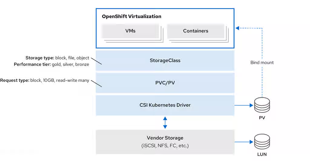
11.12. Using OpenShift Virtualization with IBM Fusion Access for SAN
You configure SAN-based storage for virtual machines by using IBM Fusion Access for SAN with OpenShift Virtualization. You must install the Fusion Access for SAN Operator (Fusion Access for SAN) and set up the storage cluster and file systems.
11.12.1. About IBM Fusion Access for SAN
IBM Fusion Access for SAN provides a scalable clustered file system for enterprise storage, primarily designed to offer access to consolidated, block-level data storage. It presents storage devices, such as disk arrays, to the operating system as if they were direct-attached storage.
IBM Fusion Access for SAN uses existing Storage Area Network (SAN) infrastructure to provide enterprise storage for OpenShift Virtualization. A SAN is a dedicated network of storage devices that is typically not accessible through the local area network (LAN).
To use OpenShift Virtualization with IBM Fusion Access for SAN, you must first install the Fusion Access for SAN Operator.
Then you must create a Kubernetes pull secret and create the FusionAccess custom resource (CR).
Finally, follow the OpenShift Container Platform web console wizard to configure the storage cluster, local disk, and file systems.
11.12.1.1. Why use Fusion Access for SAN
- Easy user experience
- Fusion Access for SAN features a wizard-driven user interface (UI) for installing and configuring storage clusters, file systems, and storage classes, to simplify the setup process.
- Use existing infrastructure
- Organizations can use their existing SAN investments, including Fibre Channel (FC) and iSCSI technologies, as they migrate to or expand with OpenShift Virtualization.
- Scalability
- The storage cluster is designed to scale with OpenShift Container Platform clusters and virtual machine (VM) workloads. It can support up to approximately 3000 VMs on 6 bare-metal hosts, with possibilities for further scaling by adding more file systems or using specific storage class parameters.
- Consolidated and shared storage
- SANs enable multiple servers to access a large, shared data storage capacity. This architecture facilitates automatic data backup and continuous monitoring of the storage and backup processes.
- High-speed data transfer
- By using a dedicated high-speed network for storage, Fusion Access for SAN overcomes the data transfer bottlenecks that can occur over a traditional LAN, especially for large volumes of data.
- File-level access
- Although a SAN primarily operates at the block level, file systems built on top of SAN storage can provide file-level access through shared-disk file systems.
- Centralized management
- The underlying SAN software manages servers, storage devices, and the network to ensure that data moves directly between storage devices with minimal server intervention. It also supports centralized management and configuration of SAN components such as Logical Unit Numbers (LUNs).
11.12.2. Prerequisites and Limitations for Fusion Access for SAN
Prerequisites and limitations are provided for installing and configuring Fusion Access for SAN.
11.12.2.1. Prerequisites
Installing and configuring Fusion Access for SAN require the following prerequisites:
- Bare-metal worker nodes with attached SAN storage.
- A working container registry enabled.
All worker nodes must connect to the same LUNs.
A shared LUN is a shared disk that is accessed by all worker nodes simultaneously.
- A Kubernetes pull secret.
11.12.2.2. Limitations
- Limitations for Fusion Access for SAN rely on the IBM Storage Scale container native limitations and can be found in the documentation for Content from www.ibm.com is not included.IBM Storage Scale container native.
- Hosted control planes (HCP) clusters are not supported.
11.12.3. Installing the Fusion Access for SAN Operator
You can install the Fusion Access for SAN Operator from the software catalog in the OpenShift Container Platform web console.
Prerequisites
-
You have access to the cluster as a user with the
cluster-adminrole. - You have a working container registry enabled.
Procedure
- In the OpenShift Container Platform web console, navigate to Ecosystem → Software Catalog.
-
In the Filter by keyword field, type
Fusion Access for SAN. - Select the Fusion Access for SAN tile and click Install.
- On the Install Operator page, keep the default selections for Update Channel, Version, and Installation mode.
Verify that Operator recommended Namespace is selected for Installed Namespace.
This installs the Operator in the
ibm-fusion-accessnamespace. If this namespace does not yet exist, it is automatically created.WarningYou must install the Fusion Access for SAN Operator in the
ibm-fusion-accessnamespace. Installation in any other namespace is not supported.Verify that the Automatic default is selected for Update Approval.
This enables automatic updates when a new z-stream release is available.
Click Install.
This installs the Operator.
Verification
- Navigate to Ecosystem → Installed Operators.
- Verify that the Fusion Access for SAN Operator is displayed.
11.12.4. Creating a Kubernetes pull secret
After installing the Fusion Access for SAN Operator, you must create a Kubernetes secret object to hold the IBM entitlement key for pulling the required container images from the IBM container registry.
Prerequisites
-
You installed the
ocCLI. -
You have access to the cluster as a user with the
cluster-adminrole. -
You installed the Fusion Access for SAN Operator and created the
ibm-fusion-accessnamespace in the process.
Procedure
- Log in to the Content from myibm.ibm.com is not included.IBM Container software library with your Fusion Access for SAN IBMid and password.
In the IBM Container software library, get the entitlement key:
- If you do not have an entitlement key yet, click Get entitlement key or Add new key, and then click Copy.
- If you already have an entitlement key, click Copy.
- Save the entitlement key in a safe place.
Create the secret object by running the
oc createcommand, replacing<ibm-entitlement-key>with the entitlement key that you copied in step 2.$ oc create secret -n ibm-fusion-access generic fusion-pullsecret \ --from-literal=ibm-entitlement-key=<ibm-entitlement-key>
Verification
- In the OpenShift Container Platform web console, navigate to Workloads → Secrets.
-
Find the
fusion-pullsecretin the list.
11.12.5. Creating the FusionAccess CR
After installing the Fusion Access for SAN Operator and creating a Kubernetes pull secret, you must create the FusionAccess custom resource (CR).
Creating the FusionAccess CR triggers the installation of the correct version of IBM Storage Scale and detects worker nodes with shared LUNs.
Prerequisites
-
You have access to the cluster as a user with the
cluster-adminrole. - You installed the Fusion Access for SAN Operator.
- You created a Kubernetes pull secret.
Procedure
- In the OpenShift Container Platform web console, navigate to Ecosystem → Installed Operators.
- Click the Fusion Access for SAN Operator you installed.
- In the Fusion Access for SAN page, select the Fusion Access tab.
- Click Create FusionAccess.
- On the Create FusionAccess page, enter the object Name.
- Optional: You can choose to add Labels if they are relevant.
- Select the IBM Storage Scale Version from the drop-down list.
- Click Create.
Verification
-
In the Fusion Access for SAN Operator page, in the Fusion Access tab, verify that the created
FusionAccessCR is displayed with the status Ready.
11.12.6. Creating a storage cluster with Fusion Access for SAN
Once you have installed the Fusion Access for SAN Operator, you can create a storage cluster with shared storage nodes.
The wizard for creating the storage cluster in the OpenShift Container Platform web console provides easy-to-follow steps and lists the relevant worker nodes with shared disks.
Prerequisites
You have bare-metal worker nodes with visible and attached shared LUNs.
A shared LUN is a shared disk that is accessed by all workers simultaneously.
- You installed the Fusion Access for SAN Operator.
-
You created the
FusionAccesscustom resource (CR) in theibm-fusion-accessnamespace.
Procedure
- In the OpenShift Container Platform web console, navigate to Storage → Fusion Access for SAN.
- Click Create storage cluster.
Select the worker nodes that have shared LUNs.
NoteYou can only select worker nodes with a minimum of 20 GB of RAM from the list.
Click Create storage cluster.
The page reloads, opening the Fusion Access for SAN page for the new storage cluster.
11.12.7. Creating a file system with Fusion Access for SAN
You need to create a file system to represent your required storage.
The file system is based on the storage available in the worker nodes you selected when creating the storage cluster.
Prerequisites
- You created a Fusion Access for SAN storage cluster.
Procedure
- In the OpenShift Container Platform web console, navigate to Storage → Fusion Access for SAN.
- In the File systems tab, click Create file system.
- Enter a Name for the new file system.
- Select the LUNs that you want to use as the storage volumes for your file system.
Click Create file system.
The Fusion Access for SAN page reloads, and the new file system is displayed in the File systems tab.
Next steps
Repeat this procedure for each file system that you want to create.
Verification
- Watch the Status of the file system in the File systems tab until it is marked as Healthy. This might take several minutes.
- Click the StorageClass for the file system.
In the YAML tab, verify the following:
-
The value in the
namefield is the name of the file system you created. -
The value in the
provisionerfield isspectrumscale.csi.ibm.com. The value in the
volBackendFsfield matches the name of the file system you created.kind: StorageClass apiVersion: storage.k8s.io/v1 metadata: name: filesystem1 uid: eb410309-a043-a89b-9bb05483872a resourceVersion: '87746' creationTimestamp: '2025-05-14T12:30:08Z' managedFields: provisioner: spectrumscale.csi.ibm.com parameters: volBackendFs: filesystem1 reclaimPolicy: Delete allowVolumeExpansion: true volumeBindingMode: Immediate
-
The value in the
11.12.8. Troubleshooting IBM Fusion Access for SAN
If you encounter issues with IBM Fusion Access for SAN, provide the must-gather image to Red Hat support. This image contains critical data about your cluster and project resources, logs, and events from your deployment.
Procedure
To obtain the deployed version of IBM Fusion Access for SAN, run the following command:
$ oc get fusionaccesses.fusion.storage.openshift.io -n ibm-fusion-access fusionaccess-sample -o jsonpath='{.spec.storageScaleVersion}'NoteThis command returns the numeric value of the deployed version of IBM Fusion Access for SAN such as
2.11.0.To create the
must-gatherimage, run the following command:$ oc adm must-gather --image=icr.io/cpopen/ibm-spectrum-scale-must-gather:v<software_version>
-
Replace
<software_version>with the IBM Fusion Access for SAN version value.
-
Replace
11.12.9. IBM Fusion Access for SAN release updates
Release updates for IBM Fusion Access for SAN, including new features, bug fixes, and known issues.
11.12.9.1. New and changed features
- IBM Fusion Access for SAN 1.1.0 includes Spectrum Scale 5.2.3.5
IBM Fusion Access for SAN 1.1.0 uses Spectrum Scale version 5.2.3.5. When you upgrade to IBM Fusion Access for SAN 1.1.0, Spectrum Scale is automatically upgraded to version 5.2.3.5.
- Backend redesign for
FileSystemClaimresources IBM Fusion Access for SAN updates the backend to use
FileSystemClaimresources for managing filesystem related objects. Previously, filesystem creation could fail if the process was interrupted. With this update, backend handling improves reliability while keeping the user interface flow and appearance unchanged.After you upgrade to IBM Fusion Access for SAN 1.1.0, resources that were created by using the 1.0 user interface are automatically migrated and associated with a
FileSystemClaimresource.- Automatic creation of
VolumeSnapshotClassresources for filesystems IBM Fusion Access for SAN now creates a
VolumeSnapshotClassresource alongside theStorageClassresource for each filesystem. This ensures that snapshot support is consistently available for newly created filesystems.After upgrading from IBM Fusion Access for SAN 1.0 to 1.1.0, a
VolumeSnapshotClassresource is automatically created for existing filesystems that did not previously have one.- Image registry requirements for kernel module management
IBM Fusion Access for SAN uses the OpenShift Container Platform image registry to manage the kernel module. Do not configure the registry to use
emptyDirstorage because it provides only temporary storage and is not suitable for production use. Configure IBM Fusion Access for SAN to use a different image registry by creating a config map and secret after installing the Operator and before creating theFusionAccessCR.
11.12.9.2. Bug fixes
- Filesystem creation button stays disabled until daemons are ready
The IBM Fusion Access for SAN Operator was updated to check the readiness of filesystem daemons before allowing a filesystem to be created. The Create file system button in the web console now stays disabled with a tooltip explaining the condition until the environment is ready. This change prevents filesystems from appearing stuck during creation.
- Filesystems cannot be deleted from the user interface
The OpenShift Container Platform web console does not support deleting filesystems. To delete a filesystem, use the OpenShift CLI (
oc).
11.12.9.3. Known issues
- Filesystem creation might fail during core pod deletion
Filesystem creation might fail if core pods are deleted at the same time. The filesystem might be partially created on the LUN, which results in the following persistent error:
Disk <ID> may still belong to an active file system
No workaround is available. Contact IBM Support for assistance.
11.12.10. Additional resources
Chapter 12. Live migration
12.1. About live migration
Live migration is the process of moving a running virtual machine (VM) to another node in the cluster without interrupting the virtual workload. Live migration enables smooth transitions during cluster upgrades or any time a node needs to be drained for maintenance or configuration changes. By default, live migration traffic is encrypted using Transport Layer Security (TLS).
12.1.1. Live migration requirements
Live migration requires shared storage, sufficient resources, and compatible CPUs across nodes.
- Live migration requirements
-
Shared storage with
ReadWriteMany(RWX) access mode. Sufficient RAM and network bandwidth.
NoteYou must ensure that there is enough memory request capacity in the cluster to support node drains that result in live migrations. You can determine the approximate required spare memory by using the following calculation:
Product of (Maximum number of nodes that can drain in parallel) and (Highest total VM memory request allocations across nodes)
The default number of migrations that can run in parallel in the cluster is 5. For more information, see "Configuring live migration" in the Additional resources section.
- If the virtual machine uses a host model CPU, the nodes must support the virtual machine’s host model CPU.
-
Shared storage with
A dedicated Multus network for live migration is highly recommended. For more information, see "Using a dedicated network for live migration" in the Additional resources section. A dedicated network minimizes the effects of network saturation on tenant workloads during migration.
12.1.2. About live migration permissions
In OpenShift Virtualization 4.19 and later, live migration operations are restricted to users who are explicitly granted the kubevirt.io:migrate cluster role. Users with this role can create, delete, and update virtual machine (VM) live migration requests.
The live migration requests are represented by VirtualMachineInstanceMigration (VMIM) custom resources. Cluster administrators can bind the kubevirt.io:migrate role to trusted users or groups at either the namespace or cluster level.
Before OpenShift Virtualization 4.19, namespace administrators had live migration permissions by default. This behavior changed in version 4.19 to prevent unintended or malicious disruptions to infrastructure-critical migration operations.
As a cluster administrator, you can preserve the old behavior by creating a temporary cluster role before updating. After assigning the new role to users, delete the temporary role to enforce the more restrictive permissions. If you have already updated, you can still revert to the old behavior by aggregating the kubevirt.io:migrate role into the admin cluster role.
12.1.3. Preserving pre-4.19 live migration permissions during update
Before you update to OpenShift Virtualization 4.21, you can create a temporary cluster role to preserve the previous live migration permissions until you are ready for the more restrictive default permissions to take effect.
Prerequisites
-
The OpenShift CLI (
oc) is installed. - You have cluster administrator permissions.
Procedure
Before updating to OpenShift Virtualization 4.21, create a temporary
ClusterRoleobject. For example:apiVersion: rbac.authorization.k8s.io/v1 kind: ClusterRole metadata: labels: rbac.authorization.k8s.io/aggregate-to-admin=true name: kubevirt.io:upgrademigrate rules: - apiGroups: - subresources.kubevirt.io resources: - virtualmachines/migrate verbs: - update - apiGroups: - kubevirt.io resources: - virtualmachineinstancemigrations verbs: - get - delete - create - update - patch - list - watch - deletecollectionThis cluster role is aggregated into the
adminrole before you update OpenShift Virtualization. The update process does not modify it, ensuring the previous behavior is maintained.Add the cluster role manifest to the cluster by running the following command:
$ oc apply -f <cluster_role_file_name>.yaml
- Update OpenShift Virtualization to version 4.21.
Bind the
kubevirt.io:migratecluster role to trusted users or groups by running one of the following commands, replacing<namespace>,<first_user>,<second_user>, and<group_name>with your own values.To bind the role at the namespace level, run the following command:
$ oc create -n <namespace> rolebinding kvmigrate --clusterrole=kubevirt.io:migrate --user=<first_user> --user=<second_user> --group=<group_name>
To bind the role at the cluster level, run the following command:
$ oc create clusterrolebinding kvmigrate --clusterrole=kubevirt.io:migrate --user=<first_user> --user=<second_user> --group=<group_name>
When you have bound the
kubevirt.io:migraterole to all necessary users, delete the temporaryClusterRoleobject by running the following command:$ oc delete clusterrole kubevirt.io:upgrademigrate
After you delete the temporary cluster role, only users with the
kubevirt.io:migraterole can create, delete, and update live migration requests.
12.1.4. Granting live migration permissions
You can grant trusted users or groups the ability to create, delete, and update live migration instances.
Prerequisites
-
The OpenShift CLI (
oc) is installed. - You have cluster administrator permissions.
Procedure
(Optional) To change the default behavior so that namespace administrators always have permission to create, delete, and update live migrations, aggregate the
kubevirt.io:migraterole into theadmincluster role by running the following command:$ oc label --overwrite clusterrole kubevirt.io:migrate rbac.authorization.k8s.io/aggregate-to-admin=true
Bind the
kubevirt.io:migratecluster role to trusted users or groups by running one of the following commands, replacing<namespace>,<first_user>,<second_user>, and<group_name>with your own values.To bind the role at the namespace level, run the following command:
$ oc create -n <namespace> rolebinding kvmigrate --clusterrole=kubevirt.io:migrate --user=<first_user> --user=<second_user> --group=<group_name>
To bind the role at the cluster level, run the following command:
$ oc create clusterrolebinding kvmigrate --clusterrole=kubevirt.io:migrate --user=<first_user> --user=<second_user> --group=<group_name>
12.1.5. VM migration tuning
You can adjust your cluster-wide live migration settings based on the type of workload and migration scenario.
This enables you to control how many VMs migrate at the same time, the network bandwidth you want to use for each migration, and how long OpenShift Virtualization attempts to complete the migration before canceling the process. Configure these settings in the HyperConverged custom resource (CR).
If you are migrating multiple VMs per node at the same time, set a bandwidthPerMigration limit to prevent a large or busy VM from using a large portion of the node’s network bandwidth. By default, the bandwidthPerMigration value is 0, which means unlimited.
A large VM running a heavy workload (for example, database processing), with higher memory dirty rates, requires a higher bandwidth to complete the migration.
Post copy mode, when enabled, triggers if the initial pre-copy phase does not complete within the defined timeout. During post copy, the VM CPUs pause on the source host while transferring the minimum required memory pages. Then the VM CPUs activate on the destination host, and the remaining memory pages transfer into the destination node at runtime. This can impact performance during the transfer.
Post copy mode should not be used for critical data, or with unstable networks.
12.1.6. Additional resources
12.2. Configuring live migration
You can configure live migration settings to ensure that the migration processes do not overwhelm the cluster. You can configure live migration policies to apply different migration configurations to groups of virtual machines (VMs).
12.2.1. Configuring live migration limits and timeouts
Configure live migration limits and timeouts for the cluster by updating the HyperConverged custom resource (CR), which is located in the openshift-cnv namespace.
Prerequisites
-
You have installed the OpenShift CLI (
oc).
Procedure
Edit the
HyperConvergedCR and add the necessary live migration parameters:$ oc edit hyperconverged kubevirt-hyperconverged -n openshift-cnv
Example configuration file:
apiVersion: hco.kubevirt.io/v1beta1 kind: HyperConverged metadata: name: kubevirt-hyperconverged namespace: openshift-cnv spec: liveMigrationConfig: bandwidthPerMigration: 64Mi completionTimeoutPerGiB: 800 parallelMigrationsPerCluster: 5 parallelOutboundMigrationsPerNode: 2 progressTimeout: 150 allowPostCopy: falsewhere:
bandwidthPerMigration- Specifies the bandwidth of each migration in bytes per second. For example, a value of 2048Mi means 2048 MiB/s. Default: 0, which is unlimited.
completionTimeoutPerGiB-
Specifies the length of time, in seconds per GiB of memory, at which the migration is canceled if it has not completed. For example, a VM with 6GiB memory times out if it has not completed migration in 4800 seconds. If the
Migration MethodisBlockMigration, the size of the migrating disks is included in the calculation. parallelMigrationsPerCluster-
Specifies the number of migrations running in parallel in the cluster. Default:
5. parallelOutboundMigrationsPerNode-
Specifies the maximum number of outbound migrations per node. Default:
2. progressTimeout-
Specifies the length of time, in seconds, at which the migration is canceled if memory copy fails to make progress. Default:
150. allowPostCopySpecifies whether the post copy mode is enabled. You can enable post copy mode to allow the migration of one node to another to converge, even if a VM is running a heavy workload and the memory dirty rate is too high. By default,
allowPostCopyis set tofalse.NoteYou can restore the default value for any
spec.liveMigrationConfigfield by deleting that key/value pair and saving the file. For example, deleteprogressTimeout: <value>to restore the defaultprogressTimeout: 150.
12.2.2. Configure live migration for heavy workloads
When migrating a VM running a heavy workload, such as database processing, higher memory dirty rates can prevent the migration from completing. To address this, you can enable post copy mode, which allows the migration to complete when the pre-copy phase cannot converge.
Configure live migration for heavy workloads by updating the HyperConverged custom resource (CR) in the openshift-cnv namespace.
Prerequisites
-
You have installed the OpenShift CLI (
oc).
Procedure
Edit the
HyperConvergedCR and add the necessary parameters for migrating heavy workloads:$ oc edit hyperconverged kubevirt-hyperconverged -n openshift-cnv
Example configuration file:
apiVersion: hco.kubevirt.io/v1beta1 kind: HyperConverged metadata: name: kubevirt-hyperconverged namespace: openshift-cnv spec: liveMigrationConfig: bandwidthPerMigration: 0Mi completionTimeoutPerGiB: 150 parallelMigrationsPerCluster: 5 parallelOutboundMigrationsPerNode: 1 progressTimeout: 150 allowPostCopy: truewhere:
bandwidthPerMigration-
Specifies the bandwidth of each migration in bytes per second. The default is
0, which is unlimited. completionTimeoutPerGiB-
Specifies the length of time, in seconds per GiB of memory, at which the migration is canceled if it has not completed and post copy mode is triggered, if enabled. You can lower
completionTimeoutPerGiBto trigger post copy mode earlier in the migration process, or raise thecompletionTimeoutPerGiBto trigger post copy mode later in the migration process. parallelMigrationsPerCluster-
Specifies the number of migrations running in parallel in the cluster. The default is
5. Keeping theparallelMigrationsPerClustersetting low is better when migrating heavy workloads. parallelOutboundMigrationsPerNode- Specifies the maximum number of outbound migrations per node. Configure a single VM per node for heavy workloads.
progressTimeout- Specifies the length of time, in seconds, at which the migration is canceled if memory copy fails to make progress. Increase this parameter for large memory sizes running heavy workloads.
allowPostCopy- Specifies whether the post copy mode is enabled. You can enable post copy mode to allow the migration of one node to another to converge, even if a VM is running a heavy workload and the memory dirty rate is too high. Set allowPostCopy to true to enable post copy mode.
Optional: If your main network is too busy for the migration, configure a secondary, dedicated migration network.
NotePost copy mode can impact performance during the transfer, and should not be used for critical data, or with unstable networks.
12.2.3. Live migration policies
You can create live migration policies to apply different migration configurations to groups of VMs that are defined by VM or project labels.
You can create live migration policies by using the OpenShift Container Platform web console.
12.2.4. Creating a live migration policy by using the CLI
You can create a live migration policy by using the command line.
KubeVirt applies the live migration policy to selected virtual machines (VMs) by using any combination of labels:
-
VM labels such as
size,os, orgpu -
Project labels such as
priority,bandwidth, orhpc-workload
For the policy to apply to a specific group of VMs, all labels on the group of VMs must match the labels of the policy.
If multiple live migration policies apply to a VM, the policy with the greatest number of matching labels takes precedence.
If multiple policies meet this criteria, the policies are sorted by alphabetical order of the matching label keys, and the first one in that order takes precedence.
Prerequisites
-
You have installed the OpenShift CLI (
oc).
Procedure
Edit the VM object to which you want to apply a live migration policy, and add the corresponding VM labels.
Open the YAML configuration of the resource:
$ oc edit vm <vm_name>
Adjust the required label values in the
.spec.template.metadata.labelssection of the configuration. For example, to mark the VM as aproductionVM for the purposes of migration policies, add thekubevirt.io/environment: productionline:apiVersion: migrations.kubevirt.io/v1alpha1 kind: VirtualMachine metadata: name: <vm_name> namespace: default labels: app: my-app environment: production spec: template: metadata: labels: kubevirt.io/domain: <vm_name> kubevirt.io/size: large kubevirt.io/environment: production # ...- Save and exit the configuration.
Configure a
MigrationPolicyobject with the corresponding labels. The following example configures a policy that applies to all VMs that are labeled asproduction:apiVersion: migrations.kubevirt.io/v1alpha1 kind: MigrationPolicy metadata: name: <migration_policy> spec: selectors: namespaceSelector: hpc-workloads: "True" xyz-workloads-type: "" virtualMachineInstanceSelector: kubevirt.io/environment: "production"where:
namespaceSelector- Specifies the project labels.
virtualMachineInstanceSelector- Specifies the VM labels.
Create the migration policy by running the following command:
$ oc create -f <migration_policy>.yaml
12.2.5. Additional resources
12.3. Initiating and canceling live migration
To move a running virtual machine (VM) to a different node without interrupting the workload, you can initiate a live migration. You can also cancel an ongoing migration to keep the VM on its original node.
You can initiate the live migration of a virtual machine (VM) to another node by using the OpenShift Container Platform web console or the command line.
You can cancel a live migration by using the web console or the command line. The VM remains on its original node.
You can also initiate and cancel live migration by using the virtctl migrate <vm_name> and virtctl migrate-cancel <vm_name> commands.
12.3.1. Initiating live migration by using the web console
You can live migrate a running virtual machine (VM) to a different node in the cluster by using the OpenShift Container Platform web console.
The Migrate action is visible to all users but only cluster administrators can initiate a live migration.
Prerequisites
-
You have the
kubevirt.io:migrateRBAC role or you are a cluster administrator. - The VM is able to be migrated.
- If the VM is configured with a host model CPU, the cluster has an available node that supports the CPU model.
Procedure
- Navigate to Virtualization → VirtualMachines in the web console.
Take either of the following steps:
-
Click the Options menu
beside the VM you want to migrate, hover over the Migrate option, and select Compute.
- Open the VM details page of the VM you want to migrate, click the Actions menu, hover over the Migrate option, and select Compute.
-
Click the Options menu
In the Migrate Virtual Machine to a different Node dialog box, select either Automatically Selected Node or Specific Node.
- If you selected the Specific Node option, choose a node from the list.
- Click Migrate Virtual Machine.
12.3.2. Initiating live migration by using the CLI
You can initiate the live migration of a running virtual machine (VM) by using the command line to create a VirtualMachineInstanceMigration object for the VM.
Prerequisites
-
You have installed the OpenShift CLI (
oc). -
You have the
kubevirt.io:migrateRBAC role or you are a cluster administrator.
Procedure
Create a
VirtualMachineInstanceMigrationmanifest for the VM that you want to migrate:apiVersion: kubevirt.io/v1 kind: VirtualMachineInstanceMigration metadata: name: <migration_name> spec: vmiName: <vm_name>
Create the object by running the following command:
$ oc create -f <migration_name>.yaml
The
VirtualMachineInstanceMigrationobject triggers a live migration of the VM. This object exists in the cluster only while the virtual machine instance is running, unless manually deleted.
Verification
Obtain the VM status by running the following command:
$ oc describe vmi <vm_name> -n <namespace>
Example output:
# ... Status: Conditions: Last Probe Time: <nil> Last Transition Time: <nil> Status: True Type: LiveMigratable Migration Method: LiveMigration Migration State: Completed: true End Timestamp: 2018-12-24T06:19:42Z Migration UID: d78c8962-0743-11e9-a540-fa163e0c69f1 Source Node: node2.example.com Start Timestamp: 2018-12-24T06:19:35Z Target Node: node1.example.com Target Node Address: 10.9.0.18:43891 Target Node Domain Detected: true
12.3.3. Canceling live migration by using the web console
You can cancel the live migration of a virtual machine (VM) by using the OpenShift Container Platform web console.
Prerequisites
-
You have the
kubevirt.io:migrateRBAC role or you are a cluster administrator.
Procedure
- Navigate to Virtualization → VirtualMachines in the web console.
-
Select Cancel Migration on the Options menu
beside a VM.
12.3.4. Canceling live migration by using the CLI
Cancel the live migration of a virtual machine by deleting the VirtualMachineInstanceMigration object associated with the migration.
Prerequisites
-
You have installed the OpenShift CLI (
oc). -
You have the
kubevirt.io:migrateRBAC role or you are a cluster administrator.
Procedure
Delete the
VirtualMachineInstanceMigrationobject that triggered the live migration,migration-jobin this example:$ oc delete vmim migration-job
12.3.5. Additional resources
12.4. Enabling cross-cluster live migration for virtual machines
Cross-cluster live migration enables users to move a virtual machine (VM) workload from one OpenShift Container Platform cluster to another cluster without disruption.
12.4.1. Prerequisites
- OpenShift Virtualization 4.20 or later must be installed.
- The OpenShift Container Platform and OpenShift Virtualization minor release versions must match. For example, if the OpenShift Container Platform version is 4.20.0, the OpenShift Virtualization must also be 4.20.0.
- Two OpenShift Container Platform clusters are required, and the migration network for both clusters must be connected to the same L2 network segment.
- You must have cluster administration privileges and appropriate RBAC privileges to manage VMs on both clusters.
12.4.2. Setting a live migration feature gate for each cluster in OpenShift Virtualization
To enable cross-cluster live migration, you must set a feature gate for each of the two clusters in OpenShift Virtualization.
Prerequisites
-
You have installed the OpenShift CLI (
oc). - You must have cluster admin privileges.
-
The
virt-synchronization-controllerpods must be running.
Procedure
Set the feature gate by running the following command for each cluster:
$ oc patch hyperconverged kubevirt-hyperconverged -n openshift-cnv --type json -p '[{"op":"replace", "path": "/spec/featureGates/decentralizedLiveMigration", "value": true}]'
Verification
To verify that the feature gate enablement is successful for each cluster, run the following command in the OpenShift Virtualization namespace to locate the synchronization pods:
$ oc get -n {CNVNamespace} pod | grep virt-synchronizationExample output:
virt-synchronization-controller-898789f8fc-nsbsm 1/1 Running 0 5d1h virt-synchronization-controller-898789f8fc-vmmfj 1/1 Running 0 5d1h
12.5. Configuring a cross-cluster live migration network
Cross-cluster live migration requires that the clusters be connected in the same network. Specifically, virt-handler pods must be able to communicate.
12.5.1. Configuration for a bridge secondary network
The Bridge CNI plugin JSON configuration object describes the configuration parameters for the Bridge CNI plugin.
The following table details the configuration parameters:
| Field | Type | Description |
|---|---|---|
|
|
|
The CNI specification version. A minimum version of |
|
|
| The mandatory, unique identifier assigned to this CNI network attachment definition. It is used by the container runtime to select the correct network configuration and serves as the key for persistent resource state management, such as IP address allocations. |
|
|
|
The name of the CNI plugin to configure: |
|
|
| The configuration object for the IPAM CNI plugin. The plugin manages IP address assignment for the attachment definition. |
|
|
|
Optional: Specify the name of the virtual bridge to use. If the bridge interface does not exist on the host, the bridge interface gets created. The default value is |
|
|
|
Optional: Set to |
|
|
|
Optional: Controls the container interface ( |
|
|
|
Optional: Set to |
|
|
|
Optional: Set to |
|
|
|
Optional: Set to |
|
|
|
Optional: Set to |
|
|
|
Optional: Set to |
|
|
| Optional: Specify a virtual LAN (VLAN) tag as an integer value. By default, no VLAN tag is assigned. |
|
|
|
Optional: Indicates whether the default VLAN must be preserved on the |
|
|
|
Optional: If |
|
|
|
Optional: Assign a VLAN trunk tag. The default value is |
|
|
| Optional: Set the maximum transmission unit (MTU) to the specified value. The default value is automatically set by the kernel. |
|
|
|
Optional: Enables duplicate address detection for the container side |
|
|
|
Optional: Enables mac spoof check, limiting the traffic originating from the container to the mac address of the interface. The default value is |
The VLAN parameter configures the VLAN tag on the host end of the veth and also enables the vlan_filtering feature on the bridge interface.
To configure an uplink for an L2 network, you must allow the VLAN on the uplink interface by using the following command:
$ bridge vlan add vid VLAN_ID dev DEV
12.5.1.1. Bridge CNI plugin configuration example
The following example configures a secondary network named bridge-net:
{
"cniVersion": "0.3.1",
"name": "bridge-net",
"type": "bridge",
"isGateway": true,
"vlan": 2,
"ipam": {
"type": "dhcp"
}
}12.5.2. Configuring a dedicated secondary network for live migration
After you have configured a Linux bridge network, you can configure a dedicated network for live migration. A dedicated network minimizes the effects of network saturation on tenant workloads during live migration.
To configure a dedicated secondary network for live migration, you must first create a bridge network attachment definition (NAD) by using the CLI. You can then add the name of the NetworkAttachmentDefinition object to the HyperConverged custom resource (CR).
Prerequisites
-
You installed the OpenShift CLI (
oc). -
You logged in to the cluster as a user with the
cluster-adminrole. - Each node has at least two Network Interface Cards (NICs).
- The NICs for live migration are connected to the same VLAN.
Procedure
Create a
NetworkAttachmentDefinitionmanifest according to the following example:apiVersion: "k8s.cni.cncf.io/v1" kind: NetworkAttachmentDefinition metadata: name: my-secondary-network namespace: openshift-cnv spec: config: '{ "cniVersion": "0.3.1", "name": "migration-bridge", "type": "macvlan", "master": "eth1", "mode": "bridge", "ipam": { "type": "whereabouts", "range": "10.200.5.0/24" } }'-
metadata.namedefines the name of theNetworkAttachmentDefinitionobject. -
config.masterdefines the name of the NIC to be used for live migration. -
config.typedefines the name of the CNI plugin that provides the network for the NAD. -
config.rangedefines an IP address range for the secondary network. This range must not overlap the IP addresses of the main network.
-
Open the
HyperConvergedCR in your default editor by running the following command:$ oc edit hyperconverged kubevirt-hyperconverged -n openshift-cnv
Add the name of the
NetworkAttachmentDefinitionobject to thespec.liveMigrationConfigstanza of theHyperConvergedCR.Example
HyperConvergedmanifest:apiVersion: hco.kubevirt.io/v1beta1 kind: HyperConverged metadata: name: kubevirt-hyperconverged namespace: openshift-cnv spec: liveMigrationConfig: completionTimeoutPerGiB: 800 network: <network> parallelMigrationsPerCluster: 5 parallelOutboundMigrationsPerNode: 2 progressTimeout: 150 # ...-
spec.liveMigrationConfig.networkdefines the name of the MultusNetworkAttachmentDefinitionobject to be used for live migrations.
-
-
Save your changes and exit the editor. The
virt-handlerpods restart and connect to the secondary network.
Verification
When the node that the virtual machine runs on is placed into maintenance mode, the VM automatically migrates to another node in the cluster. You can verify that the migration occurred over the secondary network and not the default pod network by checking the target IP address in the virtual machine instance (VMI) metadata.
$ oc get vmi <vmi_name> -o jsonpath='{.status.migrationState.targetNodeAddress}'
12.6. About Migration Toolkit for Virtualization (MTV) providers
To migrate a virtual machine (VM) across OpenShift Container Platform clusters, you must configure an OpenShift Container Platform provider for each cluster that you are including in the migration. If MTV is already installed on a cluster, a local provider already exists.
12.6.1. Configuring the root certificate authority for providers
You must configure an OpenShift Container Platform provider for each cluster that you are including in the migration, and each provider requires a certificate authority (CA) for the cluster. It is important to configure the root CA for the entire cluster to avoid CA expiration, which causes the provider to fail.
Procedure
Run the following command against the cluster for which you are creating the provider:
$ oc get cm kube-root-ca.crt -o=jsonpath={.data.ca\\.crt}- Copy the printed certificate.
- In the Migration Toolkit for Virtualization (MTV) web console, create a provider and select OpenShift Virtualization.
Paste the certificate into the CA certificate field, as shown in the following example:
-----BEGIN CERTIFICATE----- <CA_certificate_content> -----END CERTIFICATE-----
12.6.2. Creating the long-lived service account and token to use with MTV providers
When you register an OpenShift Virtualization provider in the Migration Toolkit for Virtualization (MTV) web console, you must supply credentials that allow MTV to interact with the cluster. Creating a long-lived service account and cluster role binding gives MTV persistent permissions to read and create virtual machine resources during migration.
Procedure
Create the cluster role as shown in the following example:
apiVersion: rbac.authorization.k8s.io/v1 kind: ClusterRole metadata: name: live-migration-role rules: - apiGroups: - forklift.konveyor.io resources: - '*' verbs: - get - list - watch - apiGroups: - "" resources: - secrets - namespaces - configmaps - persistentvolumes - persistentvolumeclaims verbs: - get - list - watch - create - update - patch - delete - apiGroups: - k8s.cni.cncf.io resources: - network-attachment-definitions verbs: - get - list - watch - apiGroups: - storage.k8s.io resources: - storageclasses verbs: - get - list - watch - apiGroups: - kubevirt.io resources: - virtualmachines - virtualmachines/finalizers - virtualmachineinstancemigrations verbs: - get - list - watch - create - update - patch - delete - apiGroups: - kubevirt.io resources: - kubevirts - virtualmachineinstances verbs: - get - list - watch - apiGroups: - cdi.kubevirt.io resources: - datavolumes - datavolumes/finalizers verbs: - get - list - watch - create - update - patch - delete - apiGroups: - apps resources: - deployments verbs: - get - list - watch - create - update - patch - delete - apiGroups: - instancetype.kubevirt.io resources: - virtualmachineclusterpreferences - virtualmachineclusterinstancetypes verbs: - get - list - watch - apiGroups: - instancetype.kubevirt.io resources: - virtualmachinepreferences - virtualmachineinstancetypes verbs: - get - list - watch - create - update - patch - deleteCreate the cluster role by running the following command:
$ oc create -f <filename>.yaml
Create a service account by running the following command:
$ oc create serviceaccount <service_account_name> -n <service_account_namespace>
Create a cluster role binding that links the service account to the cluster role, by running the following command:
$ oc create clusterrolebinding <service_account_name> --clusterrole=<cluster_role_name> --serviceaccount=<service_account_namespace>:<service_account_name>
Create a secret to hold the token by saving the following manifest as a YAML file:
apiVersion: v1 kind: Secret metadata: name: <name_of_secret> namespace: <namespace_for_service_account> annotations: kubernetes.io/service-account.name: <service_account_name> type: kubernetes.io/service-account-tokenApply the manifest by running the following command:
$ oc apply -f <filename>.yaml
After the secret is populated, run the following command to get the service account bearer token:
$ TOKEN_BASE64=$(oc get secret "<name_of_secret>" -n "<namespace_bound_to_service_account>" -o jsonpath='{.data.token}') TOKEN=$(echo "$TOKEN_BASE64" | base64 --decode) echo "$TOKEN"- Copy the printed token.
- In the Migration Toolkit for Virtualization (MTV) web console, when you create a provider and select OpenShift Virtualization, paste the token into the Service account bearer token field.
12.6.3. Additional resources
Chapter 13. Nodes
13.1. Node maintenance mode
Placing a node into maintenance mode marks the node as unschedulable, and removes all the VMs and pods from it. Nodes can be placed into maintenance mode by using the oc adm utility or NodeMaintenance custom resources (CRs).
Virtual machines (VMs) must have a persistent volume claim (PVC) with a shared ReadWriteMany (RWX) access mode to be live migrated.
13.1.1. Maintaining bare-metal nodes
When you deploy OpenShift Container Platform on bare metal infrastructure, there are additional considerations that must be taken into account compared to deploying on cloud infrastructure.
Unlike in cloud environments where the cluster nodes are considered ephemeral, re-provisioning a bare-metal node requires significantly more time and effort for maintenance tasks.
When a bare-metal node fails, for example, if a an unrecoverable kernel error happens or a NIC card hardware failure occurs, workloads on the failed node need to be restarted elsewhere else on the cluster while the problem node is repaired or replaced. Node maintenance mode allows cluster administrators to gracefully power down nodes, moving workloads to other parts of the cluster and ensuring workloads do not get interrupted. Detailed progress and node status details are provided during maintenance.
13.1.2. About the Node Maintenance Operator
The Node Maintenance Operator watches for new or deleted NodeMaintenance custom resources (CRs). When a new NodeMaintenance CR is detected, no new workloads are scheduled, and the node is cordoned off from the rest of the cluster. All pods that can be evicted are evicted from the node. When a NodeMaintenance CR is deleted, the node that is referenced in the CR is made available for new workloads.
Using a NodeMaintenance CR for node maintenance tasks achieves the same results as the oc adm cordon and oc adm drain commands using standard OpenShift Container Platform custom resource processing.
The node-maintenance-operator (NMO) is no longer shipped with OpenShift Virtualization. It is deployed as a standalone Operator from the software catalog in the OpenShift Container Platform web console or by using the OpenShift CLI (oc).
13.1.3. Additional resources
13.2. Configure eviction and run strategies
You can configure eviction strategies for virtual machines (VMs) or for the cluster. The default eviction strategy is LiveMigrate. The VM LiveMigrate eviction strategy ensures that a virtual machine instance (VMI) is not interrupted if the node is placed into maintenance or drained. VMIs with this eviction strategy are live migrated to another node.
Table 13.1. Cluster eviction strategies
| Eviction strategy | Description | Interrupts workflow | Blocks upgrades |
|---|---|---|---|
|
| Prioritizes workload continuity over upgrades. | No | Yes 2 |
|
| Prioritizes upgrades over workload continuity to ensure that the environment is updated. | Yes | No |
|
| Shuts down VMs with no eviction strategy. | Yes | No |
- Default eviction strategy for multi-node clusters.
- If a VM blocks an upgrade, you must shut down the VM manually.
- Default eviction strategy for single-node OpenShift.
13.2.1. Configuring a VM eviction strategy using the CLI
You can configure an eviction strategy for a virtual machine (VM) by using the command line.
The default eviction strategy is LiveMigrate. A non-migratable VM with a LiveMigrate eviction strategy might prevent nodes from draining or block an infrastructure upgrade because the VM is not evicted from the node. This situation causes a migration to remain in a Pending or Scheduling state unless you shut down the VM manually.
You must set the eviction strategy of non-migratable VMs to LiveMigrateIfPossible, which does not block an upgrade, or to None, for VMs that should not be migrated.
Prerequisites
-
You have installed the OpenShift CLI (
oc).
Procedure
Edit the
VirtualMachineresource by running the following command:$ oc edit vm <vm_name> -n <namespace>
Example eviction strategy:
apiVersion: kubevirt.io/v1 kind: VirtualMachine metadata: name: <vm_name> spec: template: spec: evictionStrategy: LiveMigrateIfPossible # ...-
spec.template.spec.evictionStrategydefines the eviction strategy. The default value isLiveMigrate.
-
Restart the VM to apply the changes:
$ virtctl restart <vm_name> -n <namespace>
13.2.2. Configuring a cluster eviction strategy by using the CLI
You can configure an eviction strategy for a cluster by using the command line.
Prerequisites
-
You have installed the OpenShift CLI (
oc).
Procedure
Edit the
hyperconvergedresource by running the following command:$ oc edit hyperconverged kubevirt-hyperconverged -n openshift-cnv
Set the cluster eviction strategy as shown in the following example:
Example cluster eviction strategy:
apiVersion: hco.kubevirt.io/v1beta1 kind: HyperConverged metadata: name: kubevirt-hyperconverged spec: evictionStrategy: LiveMigrate # ...
13.2.3. Run strategies
The spec.runStrategy key determines how a VM behaves under certain conditions. This key has four possible values: Always, RerunOnFailure, Manual, and Halted.
Always- The virtual machine instance (VMI) is always present when a virtual machine (VM) is created on another node. A new VMI is created if the original stops for any reason.
RerunOnFailureThe VMI is re-created on another node if the previous instance fails. The instance is not re-created if the VM stops successfully, such as when it is shut down.
ImportantSetting
spec.runStrategy: RerunOnFailureis an explicit command to start the VM. If the VM is intentionally stopped and you do not want it to start, do not change the run strategy value toRerunOnFailure.Manual-
You control the VMI state manually with the
start,stop, andrestartvirtctl client commands. The VM is not automatically restarted. Halted- No VMI is present when a VM is created.
Different combinations of the virtctl start, stop and restart commands affect the run strategy.
The following table describes a VM’s transition between states. The first column shows the VM’s initial run strategy. The remaining columns show a virtctl command and the new run strategy after that command is run.
Table 13.2. Run strategy before and after virtctl commands
| Initial run strategy | Start | Stop | Restart |
|---|---|---|---|
| Always | - | Halted | Always |
| RerunOnFailure | RerunOnFailure | RerunOnFailure | RerunOnFailure |
| Manual | Manual | Manual | Manual |
| Halted | Always | - | - |
If a node in a cluster installed by using installer-provisioned infrastructure fails the machine health check and is unavailable, VMs with runStrategy: Always or runStrategy: RerunOnFailure are rescheduled on a new node.
13.2.4. Configuring a VM run strategy by using the CLI
You can configure a run strategy for a virtual machine (VM) by using the command line.
Prerequisites
-
You have installed the OpenShift CLI (
oc).
Procedure
Edit the
VirtualMachineresource by running the following command:$ oc edit vm <vm_name> -n <namespace>
Example run strategy:
apiVersion: kubevirt.io/v1 kind: VirtualMachine spec: runStrategy: Always # ...
13.2.5. Delete a failed node to trigger virtual machine failover
If a node fails and machine health checks are not deployed on your cluster, virtual machines (VMs) with runStrategy: Always configured are not automatically relocated to healthy nodes. To trigger VM failover, you must manually delete the Node object. The following procedure deletes a node from an OpenShift Container Platform cluster running on bare metal.
Prerequisites
-
A node where a virtual machine was running has the
NotReadycondition. -
The virtual machine that was running on the failed node has
runStrategyset toAlways. -
You have installed the OpenShift CLI (
oc).
Procedure
Mark the node as unschedulable:
$ oc adm cordon <node_name>
Drain all pods on the node:
$ oc adm drain <node_name> --force=true
This step might fail if the node is offline or unresponsive. Even if the node does not respond, the node might still be running a workload that writes to shared storage. To avoid data corruption, power down the physical hardware before you proceed.
Delete the node from the cluster:
$ oc delete node <node_name>
Although the node object is now deleted from the cluster, it can still rejoin the cluster after reboot or if the kubelet service is restarted. To permanently delete the node and all its data, you must decommission the node.
- If you powered down the physical hardware, turn it back on so that the node can rejoin the cluster.
Verification
-
After all resources are terminated on the unhealthy node, a new virtual machine instance (VMI) is automatically created on a healthy node for each relocated VM. To confirm that the VMI was created, view all VMIs by using the OpenShift CLI (
oc).
13.2.6. Additional resources
13.3. Managing node labeling for obsolete CPU models
You can schedule a virtual machine (VM) on a node if the VM CPU model and policy are supported by the node.
13.3.1. About node labeling for obsolete CPU models
The OpenShift Virtualization Operator uses a predefined list of obsolete CPU models to ensure that a node supports only valid CPU models for scheduled VMs.
By default, the following CPU models are eliminated from the list of labels generated for the node:
Example 13.1. Obsolete CPU models
"486" Conroe athlon core2duo coreduo kvm32 kvm64 n270 pentium pentium2 pentium3 pentiumpro phenom qemu32 qemu64
This predefined list is not visible in the HyperConverged CR. You cannot remove CPU models from this list, but you can add to the list by editing the spec.obsoleteCPUs.cpuModels field of the HyperConverged CR.
13.3.2. Configuring obsolete CPU models
You can configure a list of obsolete CPU models by editing the HyperConverged custom resource (CR).
Procedure
Edit the
HyperConvergedcustom resource, specifying the obsolete CPU models in theobsoleteCPUsarray. For example:apiVersion: hco.kubevirt.io/v1beta1 kind: HyperConverged metadata: name: kubevirt-hyperconverged namespace: openshift-cnv spec: obsoleteCPUs: cpuModels: - "<obsolete_cpu_1>" - "<obsolete_cpu_2>"Replace the example values in the
cpuModelsarray with obsolete CPU models. Any value that you specify is added to a predefined list of obsolete CPU models. The predefined list is not visible in the CR.
13.4. Preventing node reconciliation
Use skip-node annotation to prevent the node-labeller from reconciling a node.
13.4.1. Using skip-node annotation
If you want the node-labeller to skip a node, annotate that node by using the OpenShift CLI (oc).
Prerequisites
-
You have installed the OpenShift CLI (
oc).
Procedure
Annotate the node that you want to skip by running the following command:
$ oc annotate node <node_name> node-labeller.kubevirt.io/skip-node=true
Replace
<node_name>with the name of the relevant node to skip.Reconciliation resumes on the next cycle after the node annotation is removed or set to false.
13.4.2. Additional resources
13.5. Activating kernel samepage merging (KSM)
OpenShift Virtualization can activate kernel samepage merging (KSM) when nodes are overloaded. KSM deduplicates identical data found in the memory pages of virtual machines (VMs). If you have very similar VMs, KSM can make it possible to schedule more VMs on a single node.
You must only use KSM with trusted workloads.
13.5.1. Prerequisites
- Ensure that an administrator has configured KSM support on any nodes where you want OpenShift Virtualization to activate KSM.
13.5.2. About using OpenShift Virtualization to activate KSM
You can configure OpenShift Virtualization to activate kernel samepage merging (KSM) when nodes experience memory overload.
13.5.2.1. Configuration methods
You can enable or disable the KSM activation feature for all nodes by using the OpenShift Container Platform web console or by editing the HyperConverged custom resource (CR). The HyperConverged CR supports more granular configuration.
- CR configuration
You can configure the KSM activation feature by editing the
spec.configuration.ksmConfigurationstanza of theHyperConvergedCR.-
You enable the feature and configure settings by editing the
ksmConfigurationstanza. -
You disable the feature by deleting the
ksmConfigurationstanza. -
You can allow OpenShift Virtualization to enable KSM on only a subset of nodes by adding node selection syntax to the
ksmConfiguration.nodeLabelSelectorfield.
NoteEven if the KSM activation feature is disabled in OpenShift Virtualization, an administrator can still enable KSM on nodes that support it.
-
You enable the feature and configure settings by editing the
13.5.2.2. KSM node labels
OpenShift Virtualization identifies nodes that are configured to support KSM and applies the following node labels:
kubevirt.io/ksm-handler-managed: "false"-
This label is set to
"true"when OpenShift Virtualization activates KSM on a node that is experiencing memory overload. This label is not set to"true"if an administrator activates KSM. kubevirt.io/ksm-enabled: "false"-
This label is set to
"true"when KSM is activated on a node, even if OpenShift Virtualization did not activate KSM.
These labels are not applied to nodes that do not support KSM.
13.5.3. Configuring KSM activation by using the web console
You can allow OpenShift Virtualization to activate kernel samepage merging (KSM) on all nodes in your cluster by using the OpenShift Container Platform web console.
Procedure
- From the side menu, click Virtualization → Overview.
- Select the Settings tab.
- Select the Cluster tab.
- Expand Resource management.
Enable or disable the feature for all nodes:
- Set Kernel Samepage Merging (KSM) to on.
- Set Kernel Samepage Merging (KSM) to off.
13.5.4. Configuring KSM activation by using the CLI
You can enable or disable OpenShift Virtualization’s kernel samepage merging (KSM) activation feature by editing the HyperConverged custom resource (CR). Use this method if you want OpenShift Virtualization to activate KSM on only a subset of nodes.
Prerequisites
-
You have installed the OpenShift CLI (
oc).
Procedure
Open the
HyperConvergedCR in your default editor by running the following command:$ oc edit hyperconverged kubevirt-hyperconverged -n openshift-cnv
Edit the
ksmConfigurationstanza:To enable the KSM activation feature for all nodes, set the
nodeLabelSelectorvalue to{}. For example:apiVersion: hco.kubevirt.io/v1beta1 kind: HyperConverged metadata: name: kubevirt-hyperconverged namespace: openshift-cnv spec: configuration: ksmConfiguration: nodeLabelSelector: {} # ...To enable the KSM activation feature on a subset of nodes, edit the
nodeLabelSelectorfield. Add syntax that matches the nodes where you want OpenShift Virtualization to enable KSM. For example, the following configuration allows OpenShift Virtualization to enable KSM on nodes where both<first_example_key>and<second_example_key>are set to"true":apiVersion: hco.kubevirt.io/v1beta1 kind: HyperConverged metadata: name: kubevirt-hyperconverged namespace: openshift-cnv spec: configuration: ksmConfiguration: nodeLabelSelector: matchLabels: <first_example_key>: "true" <second_example_key>: "true" # ...To disable the KSM activation feature, delete the
ksmConfigurationstanza. For example:apiVersion: hco.kubevirt.io/v1beta1 kind: HyperConverged metadata: name: kubevirt-hyperconverged namespace: openshift-cnv spec: configuration: # ...
- Save the file.
13.5.5. Additional resources
Chapter 14. Monitoring
14.1. Monitoring overview
Monitor the health of your cluster and virtual machines (VMs) to have a unified operational view of your environment. This ensures high availability and optimal resource performance.
You can monitor the health of your cluster and VMs with the following tools:
- Monitoring OpenShift Virtualization VM health status
- View the overall health of your OpenShift Virtualization environment in the web console by navigating to the Home → Overview page in the OpenShift Container Platform web console. The Status card displays the overall health of OpenShift Virtualization based on the alerts and conditions.
- OpenShift Container Platform cluster checkup framework
- Run automated tests with the OpenShift Container Platform cluster checkup framework to ensure that your cluster, including cluster storage, is optimally configured for OpenShift Virtualization.
- Prometheus queries for virtual resources
- Query vCPU, network, storage, and guest memory swapping usage and live migration progress.
- VM custom metrics
-
Configure the
node-exporterservice to expose internal VM metrics and processes. - VM health checks
- Configure readiness, liveness, and guest agent ping probes and a watchdog for VMs.
- Runbooks
- Diagnose and resolve issues that trigger OpenShift Virtualization alerts in the OpenShift Container Platform web console.
14.2. OpenShift Virtualization cluster checkup framework
A checkup is an automated test workload that you can use to verify if a specific cluster functionality works as expected. The cluster checkup framework uses native Kubernetes resources to configure and run the checkup.
The OpenShift Virtualization cluster checkup framework is a Technology Preview feature only. Technology Preview features are not supported with Red Hat production service level agreements (SLAs) and might not be functionally complete. Red Hat does not recommend using them in production. These features provide early access to upcoming product features, enabling customers to test functionality and provide feedback during the development process.
For more information about the support scope of Red Hat Technology Preview features, see Technology Preview Features Support Scope.
As a developer or cluster administrator, you can use predefined checkups to improve cluster maintainability, troubleshoot unexpected behavior, minimize errors, and save time. You can review the results of the checkup and share them with experts for further analysis. Vendors can write and publish checkups for features or services that they offer and verify that their customer environments are configured correctly.
Running a predefined checkup in an existing namespace involves setting up a service account for the checkup, creating the Role and RoleBinding objects for the service account, enabling permissions for the checkup, and creating the input config map and the checkup job. You can run a checkup multiple times.
You must always:
- Verify that the checkup image is from a trustworthy source before applying it.
-
Review the checkup permissions before creating the
RoleandRoleBindingobjects.
14.2.1. Additional resources
14.3. Latency checkups
You can use a latency checkup to verify network connectivity and measure latency between two virtual machines (VMs) that are attached to a secondary network interface. The predefined latency checkup uses the ping utility.
Before you run a latency checkup, you must first create a bridge interface on the cluster nodes to connect the VM’s secondary interface to any interface on the node. If you do not create a bridge interface, the VMs do not start and the job fails.
Running a predefined checkup in an existing namespace involves setting up a service account for the checkup, creating the Role and RoleBinding objects for the service account, enabling permissions for the checkup, and creating the input config map and the checkup job. You can run a checkup multiple times.
You must always:
- Verify that the checkup image is from a trustworthy source before applying it.
-
Review the checkup permissions before creating the
RoleandRoleBindingobjects.
14.3.1. Running a latency checkup by using the web console
Run a latency checkup to verify network connectivity and measure the latency between two virtual machines attached to a secondary network interface.
Prerequisites
-
You must add a
NetworkAttachmentDefinitionto the namespace.
Procedure
- Navigate to Virtualization → Checkups in the web console.
- Click the Network latency tab.
- Click Install permissions.
- Click Run checkup.
- Enter a name for the checkup in the Name field.
- Select a NetworkAttachmentDefinition from the drop-down menu.
- Optional: Set a duration for the latency sample in the Sample duration (seconds) field.
- Optional: Define a maximum latency time interval by enabling Set maximum desired latency (milliseconds) and defining the time interval.
- Optional: Target specific nodes by enabling Select nodes and specifying the Source node and Target node.
- Click Run.
Verification
- To view the status of the latency checkup, go to the Checkups list on the Latency checkup tab. Click on the name of the checkup for more details.
14.3.2. Running a latency checkup by using the CLI
You can run a latency checkup by using the CLI.
Perform the following steps:
- Create a service account, roles, and rolebindings to provide cluster access permissions to the latency checkup.
- Create a config map to provide the input to run the checkup and to store the results.
- Create a job to run the checkup.
- Review the results in the config map.
- Optional: To rerun the checkup, delete the existing config map and job and then create a new config map and job.
- When you are finished, delete the latency checkup resources.
Prerequisites
-
You installed the OpenShift CLI (
oc). - The cluster has at least two worker nodes.
- You configured a network attachment definition for a namespace.
Procedure
Create a
ServiceAccount,Role, andRoleBindingmanifest for the latency checkup.Example role manifest file:
--- apiVersion: v1 kind: ServiceAccount metadata: name: vm-latency-checkup-sa --- apiVersion: rbac.authorization.k8s.io/v1 kind: Role metadata: name: kubevirt-vm-latency-checker rules: - apiGroups: ["kubevirt.io"] resources: ["virtualmachineinstances"] verbs: ["get", "create", "delete"] - apiGroups: ["subresources.kubevirt.io"] resources: ["virtualmachineinstances/console"] verbs: ["get"] - apiGroups: ["k8s.cni.cncf.io"] resources: ["network-attachment-definitions"] verbs: ["get"] --- apiVersion: rbac.authorization.k8s.io/v1 kind: RoleBinding metadata: name: kubevirt-vm-latency-checker subjects: - kind: ServiceAccount name: vm-latency-checkup-sa roleRef: kind: Role name: kubevirt-vm-latency-checker apiGroup: rbac.authorization.k8s.io --- apiVersion: rbac.authorization.k8s.io/v1 kind: Role metadata: name: kiagnose-configmap-access rules: - apiGroups: [ "" ] resources: [ "configmaps" ] verbs: ["get", "update"] --- apiVersion: rbac.authorization.k8s.io/v1 kind: RoleBinding metadata: name: kiagnose-configmap-access subjects: - kind: ServiceAccount name: vm-latency-checkup-sa roleRef: kind: Role name: kiagnose-configmap-access apiGroup: rbac.authorization.k8s.io
Apply the
ServiceAccount,Role, andRoleBindingmanifest:$ oc apply -n <target_namespace> -f <latency_sa_roles_rolebinding>.yaml
where:
<target_namespace>-
Specifies the namespace where the checkup is to be run. This must be an existing namespace where the
NetworkAttachmentDefinitionobject resides.
Create a
ConfigMapmanifest that contains the input parameters for the checkup.Example input config map:
apiVersion: v1 kind: ConfigMap metadata: name: kubevirt-vm-latency-checkup-config labels: kiagnose/checkup-type: kubevirt-vm-latency data: spec.timeout: 5m spec.param.networkAttachmentDefinitionNamespace: <target_namespace> spec.param.networkAttachmentDefinitionName: "blue-network" spec.param.maxDesiredLatencyMilliseconds: "10" spec.param.sampleDurationSeconds: "5" spec.param.sourceNode: "worker1" spec.param.targetNode: "worker2"where:
data.spec.param.networkAttachmentDefinitionName-
Specifies the name of the
NetworkAttachmentDefinitionobject. data.spec.param.maxDesiredLatencyMilliseconds- Optional: Specifies the maximum desired latency, in milliseconds, between the virtual machines. If the measured latency exceeds this value, the checkup fails.
data.spec.param.sampleDurationSeconds- Optional: Specifies the duration of the latency check, in seconds.
data.spec.param.sourceNode-
Optional: When specified, latency is measured from this node to the target node. If the source node is specified, the
spec.param.targetNodefield cannot be empty. data.spec.param.targetNode- Optional: When specified, latency is measured from the source node to this node.
Apply the config map manifest in the target namespace:
$ oc apply -n <target_namespace> -f <latency_config_map>.yaml
Create a
Jobmanifest to run the checkup.Example job manifest:
apiVersion: batch/v1 kind: Job metadata: name: kubevirt-vm-latency-checkup labels: kiagnose/checkup-type: kubevirt-vm-latency spec: backoffLimit: 0 template: spec: serviceAccountName: vm-latency-checkup-sa restartPolicy: Never containers: - name: vm-latency-checkup image: registry.redhat.io/container-native-virtualization/vm-network-latency-checkup-rhel9:v4.21.0 securityContext: allowPrivilegeEscalation: false capabilities: drop: ["ALL"] runAsNonRoot: true seccompProfile: type: "RuntimeDefault" env: - name: CONFIGMAP_NAMESPACE value: <target_namespace> - name: CONFIGMAP_NAME value: kubevirt-vm-latency-checkup-config - name: POD_UID valueFrom: fieldRef: fieldPath: metadata.uidApply the
Jobmanifest:$ oc apply -n <target_namespace> -f <latency_job>.yaml
Wait for the job to complete:
$ oc wait job kubevirt-vm-latency-checkup -n <target_namespace> --for condition=complete --timeout 6m
Review the results of the latency checkup by running the following command. If the maximum measured latency is greater than the value of the
spec.param.maxDesiredLatencyMillisecondsattribute, the checkup fails and returns an error.$ oc get configmap kubevirt-vm-latency-checkup-config -n <target_namespace> -o yaml
Example output config map (success):
apiVersion: v1 kind: ConfigMap metadata: name: kubevirt-vm-latency-checkup-config namespace: <target_namespace> labels: kiagnose/checkup-type: kubevirt-vm-latency data: spec.timeout: 5m spec.param.networkAttachmentDefinitionNamespace: <target_namespace> spec.param.networkAttachmentDefinitionName: "blue-network" spec.param.maxDesiredLatencyMilliseconds: "10" spec.param.sampleDurationSeconds: "5" spec.param.sourceNode: "worker1" spec.param.targetNode: "worker2" status.succeeded: "true" status.failureReason: "" status.completionTimestamp: "2022-01-01T09:00:00Z" status.startTimestamp: "2022-01-01T09:00:07Z" status.result.avgLatencyNanoSec: "177000" status.result.maxLatencyNanoSec: "244000" status.result.measurementDurationSec: "5" status.result.minLatencyNanoSec: "135000" status.result.sourceNode: "worker1" status.result.targetNode: "worker2"where:
data.status.result.maxLatencyNanoSec- Specifies the maximum measured latency in nanoseconds.
Optional: To view the detailed job log in case of checkup failure, use the following command:
$ oc logs job.batch/kubevirt-vm-latency-checkup -n <target_namespace>
Delete the job and config map that you previously created by running the following commands:
$ oc delete job -n <target_namespace> kubevirt-vm-latency-checkup
$ oc delete config-map -n <target_namespace> kubevirt-vm-latency-checkup-config
Optional: If you do not plan to run another checkup, delete the roles manifest:
$ oc delete -f <latency_sa_roles_rolebinding>.yaml
14.4. Storage checkups
You can use a storage checkup to verify that the cluster storage is optimally configured for OpenShift Virtualization.
Running a predefined checkup in an existing namespace involves setting up a service account for the checkup, creating the Role and RoleBinding objects for the service account, enabling permissions for the checkup, and creating the input config map and the checkup job. You can run a checkup multiple times.
You must always:
- Verify that the checkup image is from a trustworthy source before applying it.
-
Review the checkup permissions before creating the
RoleandRoleBindingobjects.
14.4.1. Retaining resources for troubleshooting storage checkups
The predefined storage checkup includes skipTeardown configuration options, which control resource clean up after a storage checkup runs. By default, the skipTeardown field value is Never, which means that the checkup always performs teardown steps and deletes all resources after the checkup runs.
You can retain resources for further inspection in case a failure occurs by setting the skipTeardown field to onfailure.
Prerequisites
-
You have installed the OpenShift CLI (
oc).
Procedure
Run the following command to edit the
storage-checkup-configconfig map:$ oc edit configmap storage-checkup-config -n <checkup_namespace>
Configure the
skipTeardownfield to use theonfailurevalue. You can do this by modifying thestorage-checkup-configconfig map, stored in thestorage_checkup.yamlfile:apiVersion: v1 kind: ConfigMap metadata: name: storage-checkup-config namespace: <checkup_namespace> data: spec.param.skipTeardown: onfailure # ...
Reapply the
storage-checkup-configconfig map by running the following command:$ oc apply -f storage_checkup.yaml -n <checkup_namespace>
14.4.2. Running a storage checkup by using the web console
You can run a storage checkup to validate that storage is working correctly for virtual machines.
Procedure
- Navigate to Virtualization → Checkups in the web console.
- Click the Storage tab.
- Click Install permissions.
- Click Run checkup.
- Enter a name for the checkup in the Name field.
- Enter a timeout value for the checkup in the Timeout (minutes) fields.
- Click Run.
Result
You can view the status of the storage checkup in the Checkups list on the Storage tab. Click on the name of the checkup for more details.
14.4.3. Running a storage checkup by using the CLI
Use a predefined checkup to verify that the OpenShift Container Platform cluster storage is configured optimally to run OpenShift Virtualization workloads.
Prerequisites
-
You have installed the OpenShift CLI (
oc). The cluster administrator has created the required
cluster-readerpermissions for the storage checkup service account and namespace, such as in the following example:apiVersion: rbac.authorization.k8s.io/v1 kind: ClusterRoleBinding metadata: name: kubevirt-storage-checkup-clustereader roleRef: apiGroup: rbac.authorization.k8s.io kind: ClusterRole name: cluster-reader subjects: - kind: ServiceAccount name: storage-checkup-sa namespace: <target_namespace>
where:
<target_namespace>- Specifies the namespace where the checkup is to be run.
Procedure
Create a
ServiceAccount,Role, andRoleBindingmanifest file for the storage checkup.Example service account, role, and rolebinding manifest:
--- apiVersion: v1 kind: ServiceAccount metadata: name: storage-checkup-sa --- apiVersion: rbac.authorization.k8s.io/v1 kind: Role metadata: name: storage-checkup-role rules: - apiGroups: [ "" ] resources: [ "configmaps" ] verbs: ["get", "update"] - apiGroups: [ "kubevirt.io" ] resources: [ "virtualmachines" ] verbs: [ "create", "delete" ] - apiGroups: [ "kubevirt.io" ] resources: [ "virtualmachineinstances" ] verbs: [ "get" ] - apiGroups: [ "subresources.kubevirt.io" ] resources: [ "virtualmachineinstances/addvolume", "virtualmachineinstances/removevolume" ] verbs: [ "update" ] - apiGroups: [ "kubevirt.io" ] resources: [ "virtualmachineinstancemigrations" ] verbs: [ "create" ] - apiGroups: [ "cdi.kubevirt.io" ] resources: [ "datavolumes" ] verbs: [ "create", "delete" ] - apiGroups: [ "" ] resources: [ "persistentvolumeclaims" ] verbs: [ "delete" ] --- apiVersion: rbac.authorization.k8s.io/v1 kind: RoleBinding metadata: name: storage-checkup-role subjects: - kind: ServiceAccount name: storage-checkup-sa roleRef: apiGroup: rbac.authorization.k8s.io kind: Role name: storage-checkup-roleApply the
ServiceAccount,Role, andRoleBindingmanifest in the target namespace:$ oc apply -n <target_namespace> -f <storage_sa_roles_rolebinding>.yaml
Create a
ConfigMapandJobmanifest file. The config map contains the input parameters for the checkup job.Example input config map and job manifest:
--- apiVersion: v1 kind: ConfigMap metadata: name: storage-checkup-config namespace: $CHECKUP_NAMESPACE data: spec.timeout: 10m spec.param.storageClass: ocs-storagecluster-ceph-rbd-virtualization spec.param.vmiTimeout: 3m --- apiVersion: batch/v1 kind: Job metadata: name: storage-checkup namespace: $CHECKUP_NAMESPACE spec: backoffLimit: 0 template: spec: serviceAccount: storage-checkup-sa restartPolicy: Never containers: - name: storage-checkup image: quay.io/kiagnose/kubevirt-storage-checkup:main imagePullPolicy: Always env: - name: CONFIGMAP_NAMESPACE value: $CHECKUP_NAMESPACE - name: CONFIGMAP_NAME value: storage-checkup-configApply the
ConfigMapandJobmanifest file in the target namespace to run the checkup:$ oc apply -n <target_namespace> -f <storage_configmap_job>.yaml
Wait for the job to complete:
$ oc wait job storage-checkup -n <target_namespace> --for condition=complete --timeout 10m
Review the results of the checkup by running the following command:
$ oc get configmap storage-checkup-config -n <target_namespace> -o yaml
Example output config map (success):
apiVersion: v1 kind: ConfigMap metadata: name: storage-checkup-config labels: kiagnose/checkup-type: kubevirt-storage data: spec.timeout: 10m status.succeeded: "true" status.failureReason: "" status.startTimestamp: "2023-07-31T13:14:38Z" status.completionTimestamp: "2023-07-31T13:19:41Z" status.result.cnvVersion: 4.21.2 status.result.defaultStorageClass: trident-nfs status.result.goldenImagesNoDataSource: <data_import_cron_list> status.result.goldenImagesNotUpToDate: <data_import_cron_list> status.result.ocpVersion: 4.21.0 status.result.pvcBound: "true" status.result.storageProfileMissingVolumeSnapshotClass: <storage_class_list> status.result.storageProfilesWithEmptyClaimPropertySets: <storage_profile_list> status.result.storageProfilesWithSmartClone: <storage_profile_list> status.result.storageProfilesWithSpecClaimPropertySets: <storage_profile_list> status.result.storageProfilesWithRWX: |- ocs-storagecluster-ceph-rbd ocs-storagecluster-ceph-rbd-virtualization ocs-storagecluster-cephfs trident-iscsi trident-minio trident-nfs windows-vms status.result.vmBootFromGoldenImage: VMI "vmi-under-test-dhkb8" successfully booted status.result.vmHotplugVolume: |- VMI "vmi-under-test-dhkb8" hotplug volume ready VMI "vmi-under-test-dhkb8" hotplug volume removed status.result.vmLiveMigration: VMI "vmi-under-test-dhkb8" migration completed status.result.vmVolumeClone: 'DV cloneType: "csi-clone"' status.result.vmsWithNonVirtRbdStorageClass: <vm_list> status.result.vmsWithUnsetEfsStorageClass: <vm_list>-
data.status.succeededdefines if the checkup is successful (true) or not (false). -
data.status.failureReasondefines the reason for failure if the checkup fails. -
data.status.startTimestampdefines the time when the checkup started, in RFC 3339 time format. -
data.status.completionTimestampdefines the time when the checkup has completed, in RFC 3339 time format. -
data.status.result.cnvVersiondefines the OpenShift Virtualization version. -
data.status.result.defaultStorageClassdefines if there is a default storage class. -
data.status.result.goldenImagesNoDataSourcedefines the list of golden images whose data source is not ready. -
data.status.result.goldenImagesNotUpToDatedefines the list of golden images whose data import cron is not up-to-date. -
data.status.result.ocpVersiondefines the OpenShift Container Platform version. -
data.status.result.pvcBounddefines if a PVC of 10Mi has been created and bound by the provisioner. -
data.status.result.storageProfileMissingVolumeSnapshotClassdefines the list of storage profiles using snapshot-based clone but missing VolumeSnapshotClass. -
data.status.result.storageProfilesWithEmptyClaimPropertySetsdefines the list of storage profiles with unknown provisioners. -
data.status.result.storageProfilesWithSmartClonedefines the list of storage profiles with smart clone support (CSI/snapshot). -
data.status.result.storageProfilesWithSpecClaimPropertySetsdefines the list of storage profiles spec-overriden claimPropertySets. -
data.status.result.vmsWithNonVirtRbdStorageClassdefines the list of virtual machines that use the Ceph RBD storage class when the virtualization storage class exists. -
data.status.result.vmsWithUnsetEfsStorageClassdefines the list of virtual machines that use an Elastic File Store (EFS) storage class where the GID and UID are not set in the storage class.
-
Delete the job and config map that you previously created by running the following commands:
$ oc delete job -n <target_namespace> storage-checkup
$ oc delete config-map -n <target_namespace> storage-checkup-config
Optional: If you do not plan to run another checkup, delete the
ServiceAccount,Role, andRoleBindingmanifest:$ oc delete -f <storage_sa_roles_rolebinding>.yaml
14.4.4. Troubleshooting a failed storage checkup
If a storage checkup fails, there are steps that you can take to identify the reason for failure.
Prerequisites
-
You have installed the OpenShift CLI (
oc). -
You have downloaded the directory provided by the
must-gathertool.
Procedure
Review the
status.failureReasonfield in thestorage-checkup-configconfig map by running the following command and observing the output:$ oc get configmap storage-checkup-config -n <namespace> -o yaml
Example output config map:
apiVersion: v1 kind: ConfigMap metadata: name: storage-checkup-config labels: kiagnose/checkup-type: kubevirt-storage data: spec.timeout: 10m status.succeeded: "false" status.failureReason: "ErrNoDefaultStorageClass" # ...-
If the checkup has failed, the
status.succeededvalue isfalse. -
If the checkup has failed, the
status.failureReasonfield contains an error message. In this example output, theErrNoDefaultStorageClasserror message means that no default storage class is configured.
-
If the checkup has failed, the
-
Search the directory provided by the
must-gathertool for logs, events, or terms related to the error in thedata.status.failureReasonfield value.
14.4.5. Storage checkup error codes
The following error codes might appear in the storage-checkup-config config map after a storage checkup fails.
| Error code | Meaning |
|---|---|
|
| No default storage class is configured. |
|
| One or more persistent volume claims (PVCs) failed to bind. |
|
| Multiple default storage classes are configured. |
|
|
There are |
|
|
There are VMs using elastic file system (EFS) storage classes, where the GID and UID are not set in the |
|
|
One or more golden images has a |
|
|
The |
|
| Some VMs failed to boot within the expected time. |
14.5. Prometheus queries for virtual resources
Monitor the consumption of cluster infrastructure resources by using the metrics provided by OpenShift Virtualization. These metrics are also used to query live migration status.
-
To use the vCPU metric, apply the
schedstats=enablekernel argument to theMachineConfigobject. This kernel argument enables scheduler statistics used for debugging and performance tuning and adds a minor additional load to the scheduler. - For guest memory swapping queries to return data, enable memory swapping on the virtual guests.
14.5.1. Querying metrics for all projects with the OpenShift Container Platform web console
Monitor the state of a cluster and any user-defined workloads by using the OpenShift Container Platform metrics query browser. The query browser uses Prometheus Query Language (PromQL) queries to examine metrics visualized on a plot.
As a cluster administrator or as a user with view permissions for all projects, you can access metrics for all default OpenShift Container Platform and user-defined projects in the Metrics UI.
Prerequisites
-
You have access to the cluster as a user with the
cluster-admincluster role or with view permissions for all projects. -
You have installed the OpenShift CLI (
oc).
Procedure
- In the OpenShift Container Platform web console, click Observe → Metrics.
To add one or more queries, perform any of the following actions:
Option Description Select an existing query.
From the Select query drop-down list, select an existing query.
Create a custom query.
Add your Prometheus Query Language (PromQL) query to the Expression field.
As you type a PromQL expression, autocomplete suggestions appear in a drop-down list. These suggestions include functions, metrics, labels, and time tokens. Use the keyboard arrows to select one of these suggested items and then press Enter to add the item to your expression. Move your mouse pointer over a suggested item to view a brief description of that item.
Add multiple queries.
Click Add query.
Duplicate an existing query.
Click the options menu
next to the query, then choose Duplicate query.
Disable a query from being run.
Click the options menu
next to the query and choose Disable query.
To run queries that you created, click Run queries. The metrics from the queries are visualized on the plot. If a query is invalid, the UI shows an error message.
Note- When drawing time series graphs, queries that operate on large amounts of data might time out or overload the browser. To avoid this, click Hide graph and calibrate your query by using only the metrics table. Then, after finding a feasible query, enable the plot to draw the graphs.
- By default, the query table shows an expanded view that lists every metric and its current value. Click the ˅ down arrowhead to minimize the expanded view for a query.
- Optional: Save the page URL to use this set of queries again in the future.
Explore the visualized metrics. Initially, all metrics from all enabled queries are shown on the plot. Select which metrics are shown by performing any of the following actions:
Option Description Hide all metrics from a query.
Click the options menu
for the query and click Hide all series.
Hide a specific metric.
Go to the query table and click the colored square near the metric name.
Zoom into the plot and change the time range.
Perform one of the following actions:
- Visually select the time range by clicking and dragging on the plot horizontally.
- Use the menu to select the time range.
Reset the time range.
Click Reset zoom.
Display outputs for all queries at a specific point in time.
Hover over the plot at the point you are interested in. The query outputs appear in a pop-up box.
Hide the plot.
Click Hide graph.
14.5.2. Querying metrics for user-defined projects with the OpenShift Container Platform web console
Monitor user-defined workloads by using the OpenShift Container Platform metrics query browser. The query browser uses Prometheus Query Language (PromQL) queries to examine metrics visualized on a plot.
As a developer, you must specify a project name when querying metrics. You must have the required privileges to view metrics for the selected project.
Prerequisites
- You have access to the cluster as a developer or as a user with view permissions for the project that you are viewing metrics for.
- You have enabled monitoring for user-defined projects.
- You have deployed a service in a user-defined project.
-
You have created a
ServiceMonitorcustom resource definition (CRD) for the service to define how the service is monitored.
Procedure
- In the OpenShift Container Platform web console, click Observe → Metrics.
To add one or more queries, perform any of the following actions:
Option Description Select an existing query.
From the Select query drop-down list, select an existing query.
Create a custom query.
Add your Prometheus Query Language (PromQL) query to the Expression field.
As you type a PromQL expression, autocomplete suggestions appear in a drop-down list. These suggestions include functions, metrics, labels, and time tokens. Use the keyboard arrows to select one of these suggested items and then press Enter to add the item to your expression. Move your mouse pointer over a suggested item to view a brief description of that item.
Add multiple queries.
Click Add query.
Duplicate an existing query.
Click the options menu
next to the query, then choose Duplicate query.
Disable a query from being run.
Click the options menu
next to the query and choose Disable query.
To run queries that you created, click Run queries. The metrics from the queries are visualized on the plot. If a query is invalid, the UI shows an error message.
Note- When drawing time series graphs, queries that operate on large amounts of data might time out or overload the browser. To avoid this, click Hide graph and calibrate your query by using only the metrics table. Then, after finding a feasible query, enable the plot to draw the graphs.
- By default, the query table shows an expanded view that lists every metric and its current value. Click the ˅ down arrowhead to minimize the expanded view for a query.
- Optional: Save the page URL to use this set of queries again in the future.
Explore the visualized metrics. Initially, all metrics from all enabled queries are shown on the plot. Select which metrics are shown by performing any of the following actions:
Option Description Hide all metrics from a query.
Click the options menu
for the query and click Hide all series.
Hide a specific metric.
Go to the query table and click the colored square near the metric name.
Zoom into the plot and change the time range.
Perform one of the following actions:
- Visually select the time range by clicking and dragging on the plot horizontally.
- Use the menu to select the time range.
Reset the time range.
Click Reset zoom.
Display outputs for all queries at a specific point in time.
Hover over the plot at the point you are interested in. The query outputs appear in a pop-up box.
Hide the plot.
Click Hide graph.
14.5.3. Virtualization metrics
The following metric descriptions include example Prometheus Query Language (PromQL) queries. These metrics are not an API and might change between versions. For a complete list of virtualization metrics, see Content from github.com is not included.KubeVirt components metrics.
The following examples use topk queries that specify a time period. If virtual machines (VMs) are deleted during that time period, they can still appear in the query output.
14.5.3.1. vCPU metrics
The following query can identify virtual machines that are waiting for Input/Output (I/O):
kubevirt_vmi_vcpu_wait_seconds_total- Returns the wait time (in seconds) on I/O for vCPUs of a virtual machine. Type: Counter.
A value above '0' means that the vCPU wants to run, but the host scheduler cannot run it yet. This inability to run indicates that there is an issue with I/O.
To query the vCPU metric, the schedstats=enable kernel argument must first be applied to the MachineConfig object. This kernel argument enables scheduler statistics used for debugging and performance tuning and adds a minor additional load to the scheduler.
kubevirt_vmi_vcpu_delay_seconds_total- Returns the cumulative time, in seconds, that a vCPU was enqueued by the host scheduler but could not run immediately. This delay appears to the virtual machine as steal time, which is CPU time lost when the host runs other workloads. Steal time can impact performance and often indicates CPU overcommitment or contention on the host. Type: Counter.
Example vCPU delay query
The following query returns the average per-second delay over a 5-minute period. A high value may indicate CPU overcommitment or contention on the node:
irate(kubevirt_vmi_vcpu_delay_seconds_total[5m]) > 0.05
Example vCPU wait time query
The following query returns the top 3 VMs waiting for I/O at every given moment over a six-minute time period:
topk(3, sum by (name, namespace) (rate(kubevirt_vmi_vcpu_wait_seconds_total[6m]))) > 0
14.5.3.2. Network metrics
The following queries can identify virtual machines that are saturating the network:
kubevirt_vmi_network_receive_bytes_total- Returns the total amount of traffic received (in bytes) on the virtual machine’s network. Type: Counter.
kubevirt_vmi_network_transmit_bytes_total- Returns the total amount of traffic transmitted (in bytes) on the virtual machine’s network. Type: Counter.
Example network traffic query
The following query returns the top 3 VMs transmitting the most network traffic at every given moment over a six-minute time period:
topk(3, sum by (name, namespace) (rate(kubevirt_vmi_network_receive_bytes_total[6m])) + sum by (name, namespace) (rate(kubevirt_vmi_network_transmit_bytes_total[6m]))) > 0
14.5.3.3. Storage metrics
You can monitor virtual machine storage traffic and identify high-traffic VMs by using Prometheus queries.
The following queries can identify VMs that are writing large amounts of data:
kubevirt_vmi_storage_read_traffic_bytes_total- Returns the total amount (in bytes) of the virtual machine’s storage-related traffic. Type: Counter.
kubevirt_vmi_storage_write_traffic_bytes_total- Returns the total amount of storage writes (in bytes) of the virtual machine’s storage-related traffic. Type: Counter.
Example storage-related traffic queries
The following query returns the top 3 VMs performing the most storage traffic at every given moment over a six-minute time period:
topk(3, sum by (name, namespace) (rate(kubevirt_vmi_storage_read_traffic_bytes_total[6m])) + sum by (name, namespace) (rate(kubevirt_vmi_storage_write_traffic_bytes_total[6m]))) > 0
The following query returns the top 3 VMs with the highest average read latency at every given moment over a six-minute time period:
topk(3, sum by (name, namespace) (rate(kubevirt_vmi_storage_read_times_seconds_total{name='${name}',namespace='${namespace}'${clusterFilter}}[6m]) / rate(kubevirt_vmi_storage_iops_read_total{name='${name}',namespace='${namespace}'${clusterFilter}}[6m]) > 0)) > 0
The following queries can track data restored from storage snapshots:
kubevirt_vmsnapshot_disks_restored_from_source- Returns the total number of virtual machine disks restored from the source virtual machine. Type: Gauge.
kubevirt_vmsnapshot_disks_restored_from_source_bytes- Returns the amount of space in bytes restored from the source virtual machine. Type: Gauge.
Examples of storage snapshot data queries
The following query returns the total number of virtual machine disks restored from the source virtual machine:
kubevirt_vmsnapshot_disks_restored_from_source{vm_name="simple-vm", vm_namespace="default"}The following query returns the amount of space in bytes restored from the source virtual machine:
kubevirt_vmsnapshot_disks_restored_from_source_bytes{vm_name="simple-vm", vm_namespace="default"}
The following queries can determine the I/O performance of storage devices:
kubevirt_vmi_storage_iops_read_total- Returns the amount of write I/O operations the virtual machine is performing per second. Type: Counter.
kubevirt_vmi_storage_iops_write_total- Returns the amount of read I/O operations the virtual machine is performing per second. Type: Counter.
Example I/O performance query
The following query returns the top 3 VMs performing the most I/O operations per second at every given moment over a six-minute time period:
topk(3, sum by (name, namespace) (rate(kubevirt_vmi_storage_iops_read_total[6m])) + sum by (name, namespace) (rate(kubevirt_vmi_storage_iops_write_total[6m]))) > 0
14.5.3.4. Guest memory swapping metrics
The following queries can identify which swap-enabled guests are performing the most memory swapping:
kubevirt_vmi_memory_swap_in_traffic_bytes- Returns the total amount (in bytes) of memory the virtual guest is swapping in. Type: Gauge.
kubevirt_vmi_memory_swap_out_traffic_bytes- Returns the total amount (in bytes) of memory the virtual guest is swapping out. Type: Gauge.
Example memory swapping query
The following query returns the top 3 VMs where the guest is performing the most memory swapping at every given moment over a six-minute time period:
topk(3, sum by (name, namespace) (rate(kubevirt_vmi_memory_swap_in_traffic_bytes[6m])) + sum by (name, namespace) (rate(kubevirt_vmi_memory_swap_out_traffic_bytes[6m]))) > 0
Memory swapping indicates that the virtual machine is under memory pressure. Increasing the memory allocation of the virtual machine can mitigate this issue.
14.5.3.5. Monitoring AAQ operator metrics
The following metrics are exposed by the Application Aware Quota (AAQ) controller for monitoring resource quotas:
kube_application_aware_resourcequota- Returns the current quota usage and the CPU and memory limits enforced by the AAQ Operator resources. Type: Gauge.
kube_application_aware_resourcequota_creation_timestamp- Returns the time, in UNIX timestamp format, when the AAQ Operator resource is created. Type: Gauge.
14.5.3.6. VM label metrics
kubevirt_vm_labelsReturns virtual machine labels as Prometheus labels. Type: Gauge.
You can expose and ignore specific labels by editing the
kubevirt-vm-labels-configconfig map. After you apply the config map to your cluster, the configuration is loaded dynamically.Example config map:
apiVersion: v1 kind: ConfigMap metadata: name: kubevirt-vm-labels-config namespace: openshift-cnv data: allowlist: "*" ignorelist: ""
data.allowlistspecifies labels to expose.-
If
data.allowlisthas a value of"*", all labels are included. -
If
data.allowlisthas a value of"", the metric does not return any labels. -
If
data.allowlistcontains a list of label keys, only the explicitly named labels are exposed. For example:allowlist: "example.io/name,example.io/version".
-
If
data.ignorelistspecifies labels to ignore. The ignore list overrides the allow list.-
The
data.ignorelistfield does not support wildcard patterns. It can be empty or include a list of specific labels to ignore. -
If
data.ignorelisthas a value of"", no labels are ignored.
-
The
14.5.3.7. Live migration metrics
The following metrics can be queried to show live migration status.
kubevirt_vmi_migration_data_processed_bytes- The amount of guest operating system data that has migrated to the new virtual machine (VM). Type: Gauge.
kubevirt_vmi_migration_data_remaining_bytes- The amount of guest operating system data that remains to be migrated. Type: Gauge.
kubevirt_vmi_migration_memory_transfer_rate_bytes- The rate at which memory is becoming dirty in the guest operating system. Dirty memory is data that has been changed but not yet written to disk. Type: Gauge.
kubevirt_vmi_migrations_in_pending_phase- The number of pending migrations. Type: Gauge.
kubevirt_vmi_migrations_in_scheduling_phase- The number of scheduling migrations. Type: Gauge.
kubevirt_vmi_migrations_in_running_phase- The number of running migrations. Type: Gauge.
kubevirt_vmi_migration_succeeded- The number of successfully completed migrations. Type: Gauge.
kubevirt_vmi_migration_failed- The number of failed migrations. Type: Gauge.
14.5.4. Additional resources
14.6. Exposing custom metrics for virtual machines
Monitor core platform components by using the OpenShift Container Platform monitoring stack based on the Prometheus monitoring system. Additionally, enable monitoring for user-defined projects by using the CLI and query custom metrics exposed for virtual machines through the node-exporter service.
14.6.1. Configuring the node exporter service
The node-exporter agent is deployed on every virtual machine in the cluster from which you want to collect metrics. Configure the node-exporter agent as a service to expose internal metrics and processes that are associated with virtual machines.
Prerequisites
-
Install the OpenShift CLI (
oc). -
Log in to the cluster as a user with
cluster-adminprivileges. -
Create the
cluster-monitoring-configConfigMapobject in theopenshift-monitoringproject. -
Configure the
user-workload-monitoring-configConfigMapobject in theopenshift-user-workload-monitoringproject by settingenableUserWorkloadtotrue.
Procedure
Create the
ServiceYAML file. In the following example, the file is callednode-exporter-service.yaml.kind: Service apiVersion: v1 metadata: name: node-exporter-service namespace: dynamation labels: servicetype: metrics spec: ports: - name: exmet protocol: TCP port: 9100 targetPort: 9100 type: ClusterIP selector: monitor: metrics-
metadata.namedefines the node-exporter service that exposes the metrics from the virtual machines. -
metadata.namespacedefines the namespace where the service is created. -
metadata.labels.servicetypedefines the label for the service. TheServiceMonitoruses this label to match this service. -
spec.ports.namedefines the name given to the port that exposes metrics on port 9100 for theClusterIPservice. -
spec.ports.portdefines the target port used bynode-exporter-serviceto listen for requests. -
spec.ports.targetPortdefines the TCP port number of the virtual machine that is configured with themonitorlabel. -
spec.selector.monitordefines the label used to match the virtual machine’s pods. In this example, any virtual machine’s pod with the labelmonitorand a value ofmetricswill be matched.
-
Create the node-exporter service:
$ oc create -f node-exporter-service.yaml
14.6.2. Configuring a virtual machine with the node exporter service
Download the node-exporter file on to the virtual machine. Then, create a systemd service that runs the node-exporter service when the virtual machine boots.
Prerequisites
-
The pods for the component are running in the
openshift-user-workload-monitoringproject. -
Grant the
monitoring-editrole to users who need to monitor this user-defined project.
Procedure
- Log on to the virtual machine.
Download the
node-exporterfile on to the virtual machine by using the directory path that applies to the version ofnode-exporterfile.$ wget https://github.com/prometheus/node_exporter/releases/download/<version>/node_exporter-<version>.linux-<architecture>.tar.gz
Extract the executable and place it in the
/usr/bindirectory.$ sudo tar xvf node_exporter-<version>.linux-<architecture>.tar.gz \ --directory /usr/bin --strip 1 "*/node_exporter"Create a
node_exporter.servicefile in this directory path:/etc/systemd/system. Thissystemdservice file runs the node-exporter service when the virtual machine reboots.[Unit] Description=Prometheus Metrics Exporter After=network.target StartLimitIntervalSec=0 [Service] Type=simple Restart=always RestartSec=1 User=root ExecStart=/usr/bin/node_exporter [Install] WantedBy=multi-user.target
Enable and start the
systemdservice.$ sudo systemctl enable node_exporter.service
$ sudo systemctl start node_exporter.service
Verification
Verify that the node-exporter agent is reporting metrics from the virtual machine.
$ curl http://localhost:9100/metrics
Example output:
go_gc_duration_seconds{quantile="0"} 1.5244e-05 go_gc_duration_seconds{quantile="0.25"} 3.0449e-05 go_gc_duration_seconds{quantile="0.5"} 3.7913e-05
14.6.3. Creating a custom monitoring label for virtual machines
To enable queries to multiple virtual machines from a single service, you can add a custom label in the virtual machine’s YAML file.
Prerequisites
-
Install the OpenShift CLI (
oc). -
Log in as a user with
cluster-adminprivileges. - Access to the web console for stop and restart a virtual machine.
Procedure
Edit the
templatespec of your virtual machine configuration file. In this example, the labelmonitorhas the valuemetrics.spec: template: metadata: labels: monitor: metrics-
Stop and restart the virtual machine to create a new pod with the label name given to the
monitorlabel.
14.6.3.1. Querying the node-exporter service for metrics
Metrics are exposed for virtual machines through an HTTP service endpoint under the /metrics canonical name. When you query for metrics, Prometheus directly scrapes the metrics from the metrics endpoint exposed by the virtual machines and presents these metrics for viewing.
Prerequisites
-
You have access to the cluster as a user with
cluster-adminprivileges or themonitoring-editrole. - You have enabled monitoring for the user-defined project by configuring the node-exporter service.
-
You have installed the OpenShift CLI (
oc).
Procedure
Obtain the HTTP service endpoint by specifying the namespace for the service:
$ oc get service -n <namespace> <node-exporter-service>
To list all available metrics for the node-exporter service, query the
metricsresource.$ curl http://<172.30.226.162:9100>/metrics | grep -vE "^#|^$"
Example output:
node_arp_entries{device="eth0"} 1 node_boot_time_seconds 1.643153218e+09 node_context_switches_total 4.4938158e+07 node_cooling_device_cur_state{name="0",type="Processor"} 0 node_cooling_device_max_state{name="0",type="Processor"} 0 node_cpu_guest_seconds_total{cpu="0",mode="nice"} 0 node_cpu_guest_seconds_total{cpu="0",mode="user"} 0 node_cpu_seconds_total{cpu="0",mode="idle"} 1.10586485e+06 node_cpu_seconds_total{cpu="0",mode="iowait"} 37.61 node_cpu_seconds_total{cpu="0",mode="irq"} 233.91 node_cpu_seconds_total{cpu="0",mode="nice"} 551.47 node_cpu_seconds_total{cpu="0",mode="softirq"} 87.3 node_cpu_seconds_total{cpu="0",mode="steal"} 86.12 node_cpu_seconds_total{cpu="0",mode="system"} 464.15 node_cpu_seconds_total{cpu="0",mode="user"} 1075.2 node_disk_discard_time_seconds_total{device="vda"} 0 node_disk_discard_time_seconds_total{device="vdb"} 0 node_disk_discarded_sectors_total{device="vda"} 0 node_disk_discarded_sectors_total{device="vdb"} 0 node_disk_discards_completed_total{device="vda"} 0 node_disk_discards_completed_total{device="vdb"} 0 node_disk_discards_merged_total{device="vda"} 0 node_disk_discards_merged_total{device="vdb"} 0 node_disk_info{device="vda",major="252",minor="0"} 1 node_disk_info{device="vdb",major="252",minor="16"} 1 node_disk_io_now{device="vda"} 0 node_disk_io_now{device="vdb"} 0 node_disk_io_time_seconds_total{device="vda"} 174 node_disk_io_time_seconds_total{device="vdb"} 0.054 node_disk_io_time_weighted_seconds_total{device="vda"} 259.79200000000003 node_disk_io_time_weighted_seconds_total{device="vdb"} 0.039 node_disk_read_bytes_total{device="vda"} 3.71867136e+08 node_disk_read_bytes_total{device="vdb"} 366592 node_disk_read_time_seconds_total{device="vda"} 19.128 node_disk_read_time_seconds_total{device="vdb"} 0.039 node_disk_reads_completed_total{device="vda"} 5619 node_disk_reads_completed_total{device="vdb"} 96 node_disk_reads_merged_total{device="vda"} 5 node_disk_reads_merged_total{device="vdb"} 0 node_disk_write_time_seconds_total{device="vda"} 240.66400000000002 node_disk_write_time_seconds_total{device="vdb"} 0 node_disk_writes_completed_total{device="vda"} 71584 node_disk_writes_completed_total{device="vdb"} 0 node_disk_writes_merged_total{device="vda"} 19761 node_disk_writes_merged_total{device="vdb"} 0 node_disk_written_bytes_total{device="vda"} 2.007924224e+09 node_disk_written_bytes_total{device="vdb"} 0
14.6.4. Creating a ServiceMonitor resource for the node exporter service
You can use a Prometheus client library and scrape metrics from the /metrics endpoint to access and view the metrics exposed by the node-exporter service. Use a ServiceMonitor custom resource definition (CRD) to monitor the node exporter service.
Prerequisites
-
You have access to the cluster as a user with
cluster-adminprivileges or themonitoring-editrole. - You have enabled monitoring for the user-defined project by configuring the node-exporter service.
-
You have installed the OpenShift CLI (
oc).
Procedure
Create a YAML file for the
ServiceMonitorresource configuration. In this example, the service monitor matches any service with the labelmetricsand queries theexmetport every 30 seconds.apiVersion: monitoring.coreos.com/v1 kind: ServiceMonitor metadata: labels: k8s-app: node-exporter-metrics-monitor name: node-exporter-metrics-monitor namespace: dynamation spec: endpoints: - interval: 30s port: exmet scheme: http selector: matchLabels: servicetype: metrics-
metadata.namedefines the name of theServiceMonitor. -
metadata.namespacedefines the namespace where theServiceMonitoris created. -
spec.endpoints.intervaldefines the interval at which the port will be queried. -
spec.endpoints.portdefines the name of the port that is queried every 30 seconds
-
Create the
ServiceMonitorconfiguration for the node-exporter service.$ oc create -f node-exporter-metrics-monitor.yaml
14.6.4.1. Accessing the node exporter service outside the cluster
You can access the node-exporter service outside the cluster and view the exposed metrics.
Prerequisites
-
You have access to the cluster as a user with
cluster-adminprivileges or themonitoring-editrole. - You have enabled monitoring for the user-defined project by configuring the node-exporter service.
-
You have installed the OpenShift CLI (
oc).
Procedure
Expose the node-exporter service.
$ oc expose service -n <namespace> <node_exporter_service_name>
Obtain the FQDN (Fully Qualified Domain Name) for the route.
$ oc get route -o=custom-columns=NAME:.metadata.name,DNS:.spec.host
Example output:
NAME DNS node-exporter-service node-exporter-service-dynamation.apps.cluster.example.org
Use the
curlcommand to display metrics for the node-exporter service.$ curl -s http://node-exporter-service-dynamation.apps.cluster.example.org/metrics
Example output:
go_gc_duration_seconds{quantile="0"} 1.5382e-05 go_gc_duration_seconds{quantile="0.25"} 3.1163e-05 go_gc_duration_seconds{quantile="0.5"} 3.8546e-05 go_gc_duration_seconds{quantile="0.75"} 4.9139e-05 go_gc_duration_seconds{quantile="1"} 0.000189423
14.6.5. Additional resources
14.7. Exposing downward metrics for virtual machines
As an administrator, you can expose a set of host and virtual machine (VM) metrics to a guest VM by enabling the downwardMetrics feature gate and configuring a downward metrics device. You can view these metrics by using the command line or the vm-dump-metrics tool.
On Red Hat Enterprise Linux (RHEL) 9, use the command line to view downward metrics.
The vm-dump-metrics tool is not supported on the Red Hat Enterprise Linux (RHEL) 9 platform.
14.7.1. Enabling or disabling the downward metrics feature gate in a YAML file
To expose downward metrics for a host virtual machine, you can enable the downwardMetrics feature gate by editing a YAML file.
Prerequisites
- You must have administrator privileges to enable the feature gate.
-
You have installed the OpenShift CLI (
oc).
Procedure
Open the HyperConverged custom resource (CR) in your default editor by running the following command:
$ oc edit hyperconverged kubevirt-hyperconverged -n openshift-cnv
Choose to enable or disable the downwardMetrics feature gate as follows:
To enable the
downwardMetricsfeature gate, add and then setspec.featureGates.downwardMetricstotrue. For example:apiVersion: hco.kubevirt.io/v1beta1 kind: HyperConverged metadata: name: kubevirt-hyperconverged namespace: openshift-cnv spec: featureGates: downwardMetrics: true # ...To disable the
downwardMetricsfeature gate, setspec.featureGates.downwardMetricstofalse. For example:apiVersion: hco.kubevirt.io/v1beta1 kind: HyperConverged metadata: name: kubevirt-hyperconverged namespace: openshift-cnv spec: featureGates: downwardMetrics: false # ...
14.7.2. Enabling or disabling the downward metrics feature gate from the CLI
To expose downward metrics for a host virtual machine, you can enable the downwardMetrics feature gate by using the command line.
Prerequisites
- You must have administrator privileges to enable the feature gate.
-
You have installed the OpenShift CLI (
oc).
Procedure
Choose to enable or disable the
downwardMetricsfeature gate as follows:Enable the
downwardMetricsfeature gate by running the command shown in the following example:$ oc patch hco kubevirt-hyperconverged -n openshift-cnv \ --type json -p '[{"op": "replace", "path": \ "/spec/featureGates/downwardMetrics", \ "value": true}]'Disable the
downwardMetricsfeature gate by running the command shown in the following example:$ oc patch hco kubevirt-hyperconverged -n openshift-cnv \ --type json -p '[{"op": "replace", "path": \ "/spec/featureGates/downwardMetrics", \ "value": false}]'
14.7.3. Configuring a downward metrics device
You can enable the capturing of downward metrics for a host VM by creating a configuration file that includes a downwardMetrics device. Adding this device establishes that the metrics are exposed through a virtio-serial port.
Prerequisites
-
You must first enable the
downwardMetricsfeature gate.
Procedure
Edit or create a YAML file that includes a
downwardMetricsdevice, as shown in the following example:apiVersion: kubevirt.io/v1 kind: VirtualMachine metadata: name: fedora namespace: default spec: dataVolumeTemplates: - metadata: name: fedora-volume spec: sourceRef: kind: DataSource name: fedora namespace: openshift-virtualization-os-images storage: resources: {} instancetype: name: u1.medium runStrategy: Always template: metadata: labels: app.kubernetes.io/name: headless spec: domain: devices: downwardMetrics: {} subdomain: headless volumes: - dataVolume: name: fedora-volume name: rootdisk - cloudInitNoCloud: userData: | #cloud-config chpasswd: expire: false password: '<password>' user: fedora name: cloudinitdisk-
spec.domain.devices.downwardMetricsdefines thedownwardMetricsdevice. -
spec.volumes.cloudInitNoCloud.userdata.passworddefines the password for thefedorauser.
14.7.4. Viewing downward metrics by using the CLI
You can view downward metrics by entering a command from inside a guest virtual machine (VM).
Procedure
Run the following commands:
$ sudo sh -c 'printf "GET /metrics/XML\n\n" > /dev/virtio-ports/org.github.vhostmd.1'
$ sudo cat /dev/virtio-ports/org.github.vhostmd.1
14.7.5. Viewing downward metrics by using the vm-dump-metrics tool
To view downward metrics, install the vm-dump-metrics tool and then use the tool to expose the metrics results.
On Red Hat Enterprise Linux (RHEL) 9, use the command line to view downward metrics. The vm-dump-metrics tool is not supported on the Red Hat Enterprise Linux (RHEL) 9 platform.
Procedure
Install the
vm-dump-metricstool by running the following command:$ sudo dnf install -y vm-dump-metrics
Retrieve the metrics results by running the following command:
$ sudo vm-dump-metrics
Example output:
<metrics> <metric type="string" context="host"> <name>HostName</name> <value>node01</value> [...] <metric type="int64" context="host" unit="s"> <name>Time</name> <value>1619008605</value> </metric> <metric type="string" context="host"> <name>VirtualizationVendor</name> <value>kubevirt.io</value> </metric> </metrics>
14.7.6. Additional resources
14.8. Virtual machine health checks
Define probes and watchdogs in the VirtualMachine resource to configure virtual machine (VM) health checks. Health checks monitor and report the internal state of a VM.
You can configure VM health checks by defining readiness and liveness probes in the VirtualMachine resource.
14.8.1. About readiness and liveness probes
Use readiness and liveness probes to detect and handle unhealthy virtual machines (VMs). You can include one or more probes in the specification of the VM to ensure that traffic does not reach a VM that is not ready for it and that a new VM is created when a VM becomes unresponsive.
A readiness probe determines whether a VM is ready to accept service requests. If the probe fails, the VM is removed from the list of available endpoints until the VM is ready.
A liveness probe determines whether a VM is responsive. If the probe fails, the VM is deleted and a new VM is created to restore responsiveness.
You can configure readiness and liveness probes by setting the spec.readinessProbe and the spec.livenessProbe fields of the VirtualMachine object. These fields support the following tests:
- HTTP GET
- The probe determines the health of the VM by using a web hook. The test is successful if the HTTP response code is between 200 and 399. You can use an HTTP GET test with applications that return HTTP status codes when they are completely initialized.
- TCP socket
- The probe attempts to open a socket to the VM. The VM is only considered healthy if the probe can establish a connection. You can use a TCP socket test with applications that do not start listening until initialization is complete.
- Guest agent ping
-
The probe uses the
guest-pingcommand to determine if the QEMU guest agent is running on the virtual machine.
14.8.1.1. Defining an HTTP readiness probe
You can define an HTTP readiness probe by setting the spec.readinessProbe.httpGet field of the virtual machine (VM) configuration.
Prerequisites
-
You have installed the OpenShift CLI (
oc).
Procedure
Include details of the readiness probe in the VM configuration file.
Sample readiness probe with an HTTP GET test:
apiVersion: kubevirt.io/v1 kind: VirtualMachine metadata: annotations: name: fedora-vm namespace: example-namespace # ... spec: template: spec: readinessProbe: httpGet: port: 1500 path: /healthz httpHeaders: - name: Custom-Header value: Awesome initialDelaySeconds: 120 periodSeconds: 20 timeoutSeconds: 10 failureThreshold: 3 successThreshold: 3 # ...-
spec.template.spec.readinessProbe.httpGetdefines the HTTP GET request to perform to connect to the VM. -
spec.template.spec.readinessProbe.httpGet.portdefines the port of the VM that the probe queries. In the above example, the probe queries port 1500. -
spec.template.spec.readinessProbe.httpGet.pathdefines the path to access on the HTTP server. In the above example, if the handler for the server’s /healthz path returns a success code, the VM is considered to be healthy. If the handler returns a failure code, the VM is removed from the list of available endpoints. -
spec.template.spec.readinessProbe.initialDelaySecondsdefines the time, in seconds, after the VM starts before the readiness probe is initiated. -
spec.template.spec.readinessProbe.periodSecondsdefines the delay, in seconds, between performing probes. The default delay is 10 seconds. This value must be greater thantimeoutSeconds. -
spec.template.spec.readinessProbe.timeoutSecondsdefines the number of seconds of inactivity after which the probe times out and the VM is assumed to have failed. The default value is 1. This value must be lower thanperiodSeconds. -
spec.template.spec.readinessProbe.failureThresholddefines the number of times that the probe is allowed to fail. The default is 3. After the specified number of attempts, the pod is markedUnready. -
spec.template.spec.readinessProbe.successThresholddefines the number of times that the probe must report success, after a failure, to be considered successful. The default is 1.
-
Create the VM by running the following command:
$ oc create -f <file_name>.yaml
14.8.1.2. Defining a TCP readiness probe
You can define a TCP readiness probe by setting the spec.readinessProbe.tcpSocket field of the virtual machine (VM) configuration.
Prerequisites
-
You have installed the OpenShift CLI (
oc).
Procedure
Include details of the TCP readiness probe in the VM configuration file.
Sample readiness probe with a TCP socket test:
apiVersion: kubevirt.io/v1 kind: VirtualMachine metadata: annotations: name: fedora-vm namespace: example-namespace # ... spec: template: spec: readinessProbe: initialDelaySeconds: 120 periodSeconds: 20 tcpSocket: port: 1500 timeoutSeconds: 10 # ...-
spec.template.spec.readinessProbe.initialDelaySecondsdefines the time, in seconds, after the VM starts before the readiness probe is initiated. -
spec.template.spec.readinessProbe.periodSeconds`defines the delay, in seconds, between performing probes. The default delay is 10 seconds. This value must be greater than `timeoutSeconds. -
spec.template.spec.readinessProbe.tcpSocketdefines the TCP action to perform. -
spec.template.spec.readinessProbe.tcpSocket.portdefines the port of the VM that the probe queries. -
spec.template.spec.readinessProbe.timeoutSecondsdefines the number of seconds of inactivity after which the probe times out and the VM is assumed to have failed. The default value is 1. This value must be lower thanperiodSeconds.
-
Create the VM by running the following command:
$ oc create -f <file_name>.yaml
14.8.1.3. Defining an HTTP liveness probe
Define an HTTP liveness probe by setting the spec.livenessProbe.httpGet field of the virtual machine (VM) configuration. You can define both HTTP and TCP tests for liveness probes in the same way as readiness probes. This procedure configures a sample liveness probe with an HTTP GET test.
Prerequisites
-
You have installed the OpenShift CLI (
oc).
Procedure
Include details of the HTTP liveness probe in the VM configuration file.
Sample liveness probe with an HTTP GET test:
apiVersion: kubevirt.io/v1 kind: VirtualMachine metadata: annotations: name: fedora-vm namespace: example-namespace # ... spec: template: spec: livenessProbe: initialDelaySeconds: 120 periodSeconds: 20 httpGet: port: 1500 path: /healthz httpHeaders: - name: Custom-Header value: Awesome timeoutSeconds: 10 # ...-
spec.tenmplate.spec.livenessProbe.initialDelaySecondsdefines the time, in seconds, after the VM starts before the liveness probe is initiated. -
spec.tenmplate.spec.livenessProbe.periodSecondsdefines the delay, in seconds, between performing probes. The default delay is 10 seconds. This value must be greater thantimeoutSeconds. -
spec.tenmplate.spec.livenessProbe.httpGetdefines the HTTP GET request to perform to connect to the VM. -
spec.tenmplate.spec.livenessProbe.httpGet.portdefines the port of the VM that the probe queries. In the above example, the probe queries port 1500. The VM installs and runs a minimal HTTP server on port 1500 via cloud-init. -
spec.tenmplate.spec.livenessProbe.httpGet.pathdefines the path to access on the HTTP server. In the above example, if the handler for the server’s/healthzpath returns a success code, the VM is considered to be healthy. If the handler returns a failure code, the VM is deleted and a new VM is created. -
spec.tenmplate.spec.livenessProbe.timeoutSecondsdefines the number of seconds of inactivity after which the probe times out and the VM is assumed to have failed. The default value is 1. This value must be lower thanperiodSeconds.
-
Create the VM by running the following command:
$ oc create -f <file_name>.yaml
14.8.2. About watchdogs
A watchdog device monitors the agent and performs one of the following actions if the guest operating system is unresponsive:
-
poweroff: The virtual machine (VM) powers down immediately. Ifspec.runStrategyis not set tomanual, the VM reboots. reset: The VM reboots in place and the guest operating system cannot react.NoteThe reboot time might cause liveness probes to time out. If cluster-level protections detect a failed liveness probe, the VM might be forcibly rescheduled, increasing the reboot time.
-
shutdown: The VM gracefully powers down by stopping all services.
Watchdog functionality is not available for Windows VMs.
You can create a watchdog device by configuring the device for a VM and installing the watchdog agent on the guest.
14.8.2.1. Configuring a watchdog device for the virtual machine
You configure a watchdog device for the virtual machine (VM).
Prerequisites
-
For
x86systems, the VM must use a kernel that works with thei6300esbwatchdog device. If you uses390xarchitecture, the kernel must be enabled fordiag288. Red Hat Enterprise Linux (RHEL) images supporti6300esbanddiag288. -
You have installed the OpenShift CLI (
oc).
Procedure
Create a
YAMLfile with the following contents:apiVersion: kubevirt.io/v1 kind: VirtualMachine metadata: labels: kubevirt.io/vm: <vm-label> name: <vm-name> spec: runStrategy: Halted template: metadata: labels: kubevirt.io/vm: <vm-label> spec: domain: devices: watchdog: name: <watchdog> <watchdog-device-model>: action: "poweroff" # ...-
spec.template.spec.domain.devices.watchdog.name.<watchdog-device-model>defines the watchdog device model to use. Forx86specifyi6300esb. Fors390xspecifydiag288. spec.template.spec.domain.devices.watchdog.name.<watchdog-device-model>.actiondefines the watchdog device action. Specifypoweroff,reset, orshutdown. Theshutdownaction requires that the guest virtual machine is responsive to ACPI signals. Usingshutdownis not recommended.The example above configures the watchdog device on a VM with the
poweroffaction and exposes the device as/dev/watchdog.This device can now be used by the watchdog binary.
-
Apply the YAML file to your cluster by running the following command:
$ oc apply -f <file_name>.yaml
Verification
Run the following command to verify that the VM is connected to the watchdog device:
ImportantVerification steps are provided for testing watchdog functionality only and must not be run on production machines.
$ lspci | grep watchdog -i
Run one of the following commands to confirm the watchdog is active:
Trigger a kernel panic:
# echo c > /proc/sysrq-trigger
Stop the watchdog service:
# pkill -9 watchdog
14.8.2.2. Installing the watchdog agent on the guest
You can install the watchdog agent on the guest and start the watchdog service.
Procedure
- Log in to the virtual machine as root user.
This step is only required when installing on IBM Z® (
s390x). Enablewatchdogby running the following command:# modprobe diag288_wdt
Verify that the
/dev/watchdogfile path is present in the VM by running the following command:# ls /dev/watchdog
Install the
watchdogpackage and its dependencies:# yum install watchdog
Uncomment the following line in the
/etc/watchdog.conffile and save the changes:#watchdog-device = /dev/watchdog
Enable the
watchdogservice to start on boot:# systemctl enable --now watchdog.service
14.8.3. Defining a guest agent ping probe
You can define a guest agent ping probe by setting the spec.readinessProbe.guestAgentPing field of the virtual machine (VM) configuration.
Prerequisites
- The QEMU guest agent must be installed and enabled on the virtual machine.
-
You have installed the OpenShift CLI (
oc).
Procedure
Include details of the guest agent ping probe in the VM configuration file. For example:
apiVersion: kubevirt.io/v1 kind: VirtualMachine metadata: annotations: name: fedora-vm namespace: example-namespace # ... spec: template: spec: readinessProbe: guestAgentPing: {} initialDelaySeconds: 120 periodSeconds: 20 timeoutSeconds: 10 failureThreshold: 3 successThreshold: 3 # ...-
spec.template.spec.readinessProbe.guestAgentPingdefines the guest agent ping probe to connect to the VM. -
spec.template.spec.readinessProbe.initialDelaySecondsdefines the time, in seconds, after the VM starts before the guest agent probe is initiated. This value is optional. -
spec.template.spec.readinessProbe.periodSecondsdefines the delay, in seconds, between performing probes. The default delay is 10 seconds. This value must be greater thantimeoutSeconds. This value is optional -
spec.template.spec.readinessProbe.timeoutSecondsdefines the number of seconds of inactivity after which the probe times out and the VM is assumed to have failed. The default value is 1. This value must be lower thanperiodSeconds. This value is optional. -
spec.template.spec.readinessProbe.failureThresholddefines the number of times that the probe is allowed to fail. The default is 3. After the specified number of attempts, the pod is markedUnready. This value is optional. -
spec.template.spec.readinessProbe.successThresholddefines the number of times that the probe must report success, after a failure, to be considered successful. The default is 1. This value is optional.
-
Create the VM by running the following command:
$ oc create -f <file_name>.yaml
14.8.4. Additional resources
14.9. OpenShift Virtualization runbooks
To diagnose and resolve OpenShift Virtualization alerts, you can use the OpenShift Virtualization Operator runbooks. These guides help ensure you can effectively troubleshoot cluster issues and restore system health.
Runbooks for the OpenShift Virtualization Operator are maintained in the Content from github.com is not included.openshift/runbooks Git repository, and you can view them on GitHub.
Table 14.1. Runbooks for OpenShift Virtualization alerts
| Alert | GitHub link |
|---|---|
|
| |
|
| |
|
| |
|
| |
|
| |
|
| |
|
| |
|
| |
|
| |
|
| |
|
| |
|
| |
|
| |
|
| |
|
| |
|
| |
|
| |
|
| |
|
| |
|
| |
|
| |
|
| |
|
| |
|
| |
|
| |
|
| |
|
| |
|
| |
|
| |
|
| |
|
| |
|
| |
|
| |
|
| |
|
| |
|
| |
|
| |
|
| |
|
| |
|
| |
|
| |
|
| |
|
| |
|
| |
|
| |
|
| |
|
| |
|
| |
|
| |
|
| |
|
| |
|
| |
|
| |
|
| |
|
| |
|
| |
|
| |
|
| |
|
| |
|
| |
|
| |
|
| |
|
| |
|
| |
|
| |
|
| |
|
|
14.9.1. Runbooks for deprecated alerts
Deprecated alerts no longer report actual issues and you can safely ignore them.
Table 14.2. Runbooks for deprecated OpenShift Virtualization alerts
| Alert | GitHub link | Notes |
|---|---|---|
|
| - | |
|
| - | |
|
| - | |
|
| - | |
|
| - | |
|
| - | |
|
| - | |
|
| - | |
|
| - | |
|
| - | |
|
| - | |
|
| - | |
|
|
Renamed to |
Chapter 15. Support
15.1. Support overview
Accelerate the resolution of cluster and virtual machine (VM) issues by using the integrated diagnostic tools and support provided by OpenShift Virtualization.
To gather debugging information, configure Prometheus and Alertmanager and collect must-gather data for OpenShift Container Platform and OpenShift Virtualization.
15.1.1. Opening a support case
Open a support case with Red Hat Support when you encounter an issue that requires immediate assistance.
15.1.1.1. Collecting data for Red Hat Support
Gather information about the issue affecting your environment to submit with your support case. This aids Red Hat Support in effectively diagnosing your issue.
Gather troubleshooting information by using the following tools:
- Configure Prometheus and Alertmanager.
-
Configure and use the
must-gathertool. -
Collect
must-gatherdata and memory dumps from VMs. -
Collect
must-gatherdata for OpenShift Container Platform and OpenShift Virtualization
15.1.1.2. Submitting a support case
Submit a support case to resolve a cluster issue that is affecting the ability of OpenShift Virtualization to function properly in your environment.
You can submit a support case to Red Hat Support by using the Customer Support page. Include data that you collected about your issue with your support request.
15.1.1.3. Creating a Jira issue
To report an issue with your environment to Red Hat Support, create a Jira issue in the OpenShift Virtualization (CNV) Jira project.
Procedure
- Log in to Red Hat Atlassian Jira.
- Access the Create Issue page.
- Select OpenShift Virtualization (CNV) as the Project.
- Select Bug as the Issue Type.
- Click Next.
- Complete the Summary and Description fields. In the Description field, include a detailed description of the issue.
Submit any collected troubleshooting information.
- Add any textual troubleshooting information, such as command outputs, in the Description field.
- Add troubleshooting files using the Attachment field.
- Select the appropriate component from Components.
- Click Create.
- Review the details of the bug you created.
15.1.2. Web console monitoring
Monitor cluster and virtual machine (VM) health with the OpenShift Container Platform web console.
The OpenShift Container Platform web console displays resource usage, alerts, events, and trends for your cluster and for OpenShift Virtualization components and resources.
Table 15.1. Web console pages for monitoring and troubleshooting
| Page | Description |
|---|---|
| Overview page | Cluster details, status, alerts, inventory, and resource usage |
| Virtualization → Overview tab | OpenShift Virtualization resources, usage, alerts, and status |
| Virtualization → Top consumers tab | Top consumers of CPU, memory, and storage |
| Virtualization → Migrations tab | Progress of live migrations |
| Virtualization → VirtualMachines tab | CPU, memory, and storage usage summary |
| Virtualization → VirtualMachines → VirtualMachine details → Metrics tab | VM resource usage, storage, network, and migration |
| Virtualization → VirtualMachines → VirtualMachine details → Events tab | List of VM events |
| Virtualization → VirtualMachines → VirtualMachine details → Diagnostics tab | VM status conditions and volume snapshot status |
15.1.3. Additional resources
15.2. Collecting data for Red Hat Support
When you submit a support case to Red Hat Support, it is helpful to provide debugging information for OpenShift Container Platform and OpenShift Virtualization by using the following tools:
- must-gather tool
-
The
must-gathertool collects diagnostic information, including resource definitions and service logs. - Prometheus
- Prometheus is a time-series database and a rule evaluation engine for metrics. Prometheus sends alerts to Alertmanager for processing.
- Alertmanager
- The Alertmanager service handles alerts received from Prometheus. The Alertmanager is also responsible for sending the alerts to external notification systems.
15.2.1. Collecting data about your environment
Collecting data about your environment minimizes the time required to analyze and determine the root cause.
Prerequisites
- You have set the retention time for Prometheus metrics data to a minimum of seven days.
- You have configured the Alertmanager to capture relevant alerts and to send alert notifications to a dedicated mailbox so that they can be viewed and persisted outside the cluster.
- You have recorded the exact number of affected nodes and virtual machines.
Procedure
- Collect must-gather data for the cluster.
- Collect must-gather data for Red Hat OpenShift Data Foundation, if necessary.
- Collect must-gather data for OpenShift Virtualization.
- Collect Prometheus metrics for the cluster.
15.2.2. Collecting data about virtual machines
Collecting data about malfunctioning virtual machines (VMs) minimizes the time required to analyze and determine the root cause.
Prerequisites
- For Linux VMs, you have installed the latest QEMU guest agent.
For Windows VMs, you have:
- Recorded the Windows patch update details.
- Installed the latest VirtIO drivers.
- Installed the latest QEMU guest agent.
- If Remote Desktop Protocol (RDP) is enabled, you have connected by using the desktop viewer to determine whether there is a problem with the connection software.
Procedure
-
Collect must-gather data for the VMs using the
/usr/bin/gatherscript. - Collect screenshots of VMs that have crashed before you restart them.
- Collect memory dumps from VMs before remediation attempts.
- Record factors that the malfunctioning VMs have in common. For example, the VMs have the same host or network.
15.2.3. Using the must-gather tool for OpenShift Virtualization
You can collect data about OpenShift Virtualization resources by running the must-gather command with the OpenShift Virtualization image.
The default data collection includes information about the following resources:
- OpenShift Virtualization Operator namespaces, including child objects
- OpenShift Virtualization custom resource definitions
- Namespaces that contain virtual machines
- Basic virtual machine definitions
You can add optional environment details and scripts to the must-gather command to collect additional information. Use these environment variables and scripts to collect data about specific VMs, images, or instance types.
Prerequisites
-
You have installed the OpenShift CLI (
oc).
Procedure
Run the
must-gathercommand to collect data about OpenShift Virtualization:$ oc adm must-gather \ --image=registry.redhat.io/container-native-virtualization/cnv-must-gather-rhel9:v4.21.8 \ -- /usr/bin/gather
NoteYou can also collect
must-gatherlogs for all Operators and products on your cluster by running following command:$ oc adm must-gather --all-images
Run the following command to modify the number of processes running in parallel when collecting
must-gatherdata:$ oc adm must-gather \ --image=registry.redhat.io/container-native-virtualization/cnv-must-gather-rhel9:v4.21.8 \ -- PROS=<number> /usr/bin/gather
PROSdefines the number of parallel processes running to collect data. The default number of processes is 5. Increasing the number of processes may result in faster data collection, but uses more resources. Increasing the maximum number of parallel processes is not recommended.Run the following command to collect detailed information for a specific VM in a specific namespace:
$ oc adm must-gather \ --image=registry.redhat.io/container-native-virtualization/cnv-must-gather-rhel9:v4.21.8 \ -- NS=<namespace name> VM=<VM name> /usr/bin/gather --vms_details
NSis the environment variable fornamespace. It is mandatory when using theVMenvironment variable.Run the following command to collect image, image-stream, and image-stream-tags information from the cluster:
$ oc adm must-gather \ --image=registry.redhat.io/container-native-virtualization/cnv-must-gather-rhel9:v4.21.8 \ /usr/bin/gather --images
Run the following command to collect information about instance types from the cluster:
$ oc adm must-gather \ --image=registry.redhat.io/container-native-virtualization/cnv-must-gather-rhel9:v4.21.8 \ /usr/bin/gather --instancetypes
15.2.3.1. must-gather tool options
To troubleshoot complex issues and collect specific data beyond the default logs, add optional parameters to the must-gather command when gathering information from your cluster.
You can specify a combination of scripts and environment variables for the following options:
- Collecting detailed virtual machine (VM) information from a namespace
- Collecting detailed information about specified VMs
- Collecting image, image-stream, and image-stream-tags information
-
Limiting the maximum number of parallel processes used by the
must-gathertool
15.2.3.1.1. Environment variables
You can specify environment variables for a compatible script.
NS=<namespace_name>-
Collect virtual machine information, including
virt-launcherpod details, from the namespace that you specify. TheVirtualMachineandVirtualMachineInstanceCR data is collected for all namespaces. VM=<vm_name>-
Collect details about a particular virtual machine. To use this option, you must also specify a namespace by using the
NSenvironment variable. PROS=<number_of_processes>Modify the maximum number of parallel processes that the
must-gathertool uses. The default value is5.ImportantUsing too many parallel processes can cause performance issues. Increasing the maximum number of parallel processes is not recommended.
15.2.3.1.2. Scripts
Each script is compatible only with certain environment variable combinations.
/usr/bin/gather-
Use the default
must-gatherscript, which collects cluster data from all namespaces and includes only basic VM information. This script is compatible only with thePROSvariable. /usr/bin/gather --vms_details-
Collect VM log files, VM definitions, control-plane logs, and namespaces that belong to OpenShift Virtualization resources. Specifying namespaces includes their child objects. If you use this parameter without specifying a namespace or VM, the
must-gathertool collects this data for all VMs in the cluster. This script is compatible with all environment variables, but you must specify a namespace if you use theVMvariable. /usr/bin/gather --images-
Collect image, image-stream, and image-stream-tags custom resource information. This script is compatible only with the
PROSvariable. /usr/bin/gather --instancetypes- Collect instance types information. This information is not currently collected by default; you can, however, optionally collect it.
15.2.3.1.3. Usage and examples
You can run a script by itself or with one or more compatible environment variables.
must-gather syntax with optional parameters
$ oc adm must-gather \ --image=registry.redhat.io/container-native-virtualization/cnv-must-gather-rhel9:v4.21.8 \ -- <environment_variable_1> <environment_variable_2> <script_name>
Table 15.2. Compatible parameters
| Script | Compatible environment variable |
|---|---|
|
|
* |
|
|
* For a namespace:
* For a VM:
* |
|
|
* |
15.2.4. Generating a VM memory dump
When a virtual machine (VM) terminates unexpectedly, you can use the virtctl memory-dump to generate a memory dump command to output a VM memory dump and save it on a persistent volume claim (PVC). Afterwards, you can analyze the memory dump to diagnose and troubleshoot issues on the VM.
Procedure
Optional: You have an existing PVC on which you want to save the memory dump.
-
The PVC volume mode must be
FileSystem. The PVC must be large enough to contain the memory dump.
The formula for calculating the PVC size is
(VMMemorySize + 100Mi) * (1 + FileSystemOverhead), where100Miis the memory dump overhead, andFileSystemOverheadis defined in theHCOobject.
-
The PVC volume mode must be
Create a memory dump of the required VM:
If you have an existing PVC selected on which you want to save the memory dump:
$ virtctl memory-dump get <vm_name> --claim-name=<pvc_name>
If you want to create a new PVC for the memory dump:
$ virtctl memory-dump get <vm_name> --claim-name=<new_pvc_name> --create-claim
Download the memory dump:
$ virtctl memory-dump download <vm_name> --output=<output_file>
Attach the memory dump to a Red Hat Support case.
Alternatively, you can inspect the memory dump, for example by using the volatility3 tool.
Optional: Remove the memory dump:
$ virtctl memory-dump remove <vm_name>
15.2.5. Additional resources
- VM support overview
- How to provide log files to Red Hat Support (Red Hat Knowledgebase)
- About OpenShift Container Platform monitoring
- Installing the QEMU guest agent on a Linux VM
- Installing VirtIO drivers from a SATA CD drive on an existing Windows VM
- Connect to the desktop viewer by using the web console
- Collect memory dumps from VMs
- Submitting a support case
- Modifying retention time and size for Prometheus metrics data
- Configuring the Alertmanager to capture relevant alerts and to send alert notifications to a dedicated mailbox
- Modifying retention time and size for Prometheus metrics data
- Configuring alerts and notifications
- This content is not included.Downloading log files and diagnostic information
- Querying metrics for all projects with the monitoring dashboard
- Installing the latest VirtIO drivers
- Content from github.com is not included.Volatility3 tool
- This content is not included.Customer Support
- Content from redhat.atlassian.net is not included.Create issue
15.3. Troubleshooting
To diagnose and resolve issues with virtual machine (VM) and cluster components, you can troubleshoot OpenShift Virtualization by using the web console or the OpenShift CLI (oc). These practices help ensure your virtualized infrastructure remains healthy.
15.3.1. Events
To monitor and troubleshoot virtual machine (VM), namespace, and resource issues, you can review OpenShift Container Platform events. Tracking this life-cycle information helps ensure you maintain a healthy cluster environment.
Procedure
- To view VM events, go to VirtualMachine details → Events in the web console.
To view namespace events, run the following command:
$ oc get events -n <namespace>
To view resource events, run the following command:
$ oc describe <resource> <resource_name>
15.3.2. Pod logs
To diagnose issues and monitor OpenShift Virtualization pods, you can view logs using the web console or the CLI. You can also view aggregated logs using the LokiStack in the web console.
15.3.2.1. Configuring OpenShift Virtualization pod log verbosity
To gather more detailed diagnostic information for troubleshooting, you can configure the verbosity level of OpenShift Virtualization pod logs. Edit the HyperConverged custom resource (CR) to configure this setting.
Prerequisites
-
You have installed the OpenShift CLI (
oc).
Procedure
To set log verbosity for specific components, open the
HyperConvergedCR in your default text editor by running the following command:$ oc edit hyperconverged kubevirt-hyperconverged -n openshift-cnv
Set the log level for one or more components by editing the
spec.logVerbosityConfigstanza. For example:apiVersion: hco.kubevirt.io/v1beta1 kind: HyperConverged metadata: name: kubevirt-hyperconverged spec: logVerbosityConfig: kubevirt: virtAPI: 5 virtController: 4 virtHandler: 3 virtLauncher: 2 virtOperator: 6The log verbosity value must be an integer in the range
1–9, where a higher number indicates a more detailed log. In this example, thevirtAPIcomponent logs are exposed if their priority level is5or higher.- Apply your changes by saving and exiting the editor.
15.3.2.2. Viewing virt-launcher pod logs with the web console
To diagnose and troubleshoot virtual machine issues, you can view the virt-launcher pod logs by using the OpenShift Container Platform web console.
Procedure
- Navigate to Virtualization → VirtualMachines.
- Select a virtual machine to open the VirtualMachine details page.
- On the General tile, click the pod name to open the Pod details page.
- Click the Logs tab to view the logs.
15.3.2.3. Viewing OpenShift Virtualization pod logs with the CLI
To diagnose issues and monitor OpenShift Virtualization pods, you can view logs by using the OpenShift CLI (oc).
Prerequisites
-
You have installed the OpenShift CLI (
oc).
Procedure
View a list of pods in the OpenShift Virtualization namespace by running the following command:
$ oc get pods -n openshift-cnv
Example output:
NAME READY STATUS RESTARTS AGE disks-images-provider-7gqbc 1/1 Running 0 32m disks-images-provider-vg4kx 1/1 Running 0 32m virt-api-57fcc4497b-7qfmc 1/1 Running 0 31m virt-api-57fcc4497b-tx9nc 1/1 Running 0 31m virt-controller-76c784655f-7fp6m 1/1 Running 0 30m virt-controller-76c784655f-f4pbd 1/1 Running 0 30m virt-handler-2m86x 1/1 Running 0 30m virt-handler-9qs6z 1/1 Running 0 30m virt-operator-7ccfdbf65f-q5snk 1/1 Running 0 32m virt-operator-7ccfdbf65f-vllz8 1/1 Running 0 32m
View the pod log by running the following command:
$ oc logs -n openshift-cnv <pod_name>
NoteIf a pod fails to start, you can use the
--previousoption to view logs from the last attempt.To monitor log output in real time, use the
-foption.Example output:
{"component":"virt-handler","level":"info","msg":"set verbosity to 2","pos":"virt-handler.go:453","timestamp":"2022-04-17T08:58:37.373695Z"} {"component":"virt-handler","level":"info","msg":"set verbosity to 2","pos":"virt-handler.go:453","timestamp":"2022-04-17T08:58:37.373726Z"} {"component":"virt-handler","level":"info","msg":"setting rate limiter to 5 QPS and 10 Burst","pos":"virt-handler.go:462","timestamp":"2022-04-17T08:58:37.373782Z"} {"component":"virt-handler","level":"info","msg":"CPU features of a minimum baseline CPU model: map[apic:true clflush:true cmov:true cx16:true cx8:true de:true fpu:true fxsr:true lahf_lm:true lm:true mca:true mce:true mmx:true msr:true mtrr:true nx:true pae:true pat:true pge:true pni:true pse:true pse36:true sep:true sse:true sse2:true sse4.1:true ssse3:true syscall:true tsc:true]","pos":"cpu_plugin.go:96","timestamp":"2022-04-17T08:58:37.390221Z"} {"component":"virt-handler","level":"warning","msg":"host model mode is expected to contain only one model","pos":"cpu_plugin.go:103","timestamp":"2022-04-17T08:58:37.390263Z"} {"component":"virt-handler","level":"info","msg":"node-labeller is running","pos":"node_labeller.go:94","timestamp":"2022-04-17T08:58:37.391011Z"}
15.3.3. Guest system logs
To diagnose issues with virtual machine (VM) guests, you can configure access to and view their boot logs using the OpenShift Container Platform web console or the OpenShift CLI (oc).
If the guest VM has no network, you can access it using its VNC or serial console.
This feature is disabled by default. If a VM does not explicitly have this setting enabled or disabled, it inherits the cluster-wide default setting.
If sensitive information such as credentials or other personally identifiable information (PII) is written to the serial console, it is logged with all other visible text. Use SSH to send sensitive data.
15.3.3.1. Enabling default access to guest system logs with the web console
To troubleshoot issues more easily, you can enable default access to virtual machine (VM) guest system logs by using the web console.
Procedure
- From the side menu, click Virtualization → Overview.
- Click the Settings tab.
- Click Cluster → Guest management.
- Set Enable guest system log access to on.
- Optional: If you want to hide the VM user credentials that were set by using cloud-init, set Hide guest credentials for non-privileged users to on.
15.3.3.2. Enabling default access to guest system logs with the CLI
To troubleshoot issues more easily, you can enable default access to virtual machine (VM) guest system logs by editing the HyperConverged custom resource (CR).
Prerequisites
-
You have installed the OpenShift CLI (
oc).
Procedure
Open the
HyperConvergedCR in your default editor by running the following command:$ oc edit hyperconverged kubevirt-hyperconverged -n openshift-cnv
Update the
disableSerialConsoleLogvalue. For example:kind: HyperConverged metadata: name: kubevirt-hyperconverged spec: virtualMachineOptions: disableSerialConsoleLog: true #...Set the value of
disableSerialConsoleLogtofalseif you want serial console access to be enabled on VMs by default.
15.3.3.3. Setting guest system log access for a single VM with the web console
To troubleshoot a specific virtual machine (VM) without changing global settings, you can configure the guest system log access by using the web console.
Procedure
- Click Virtualization → VirtualMachines from the side menu.
- Select a virtual machine to open the VirtualMachine details page.
- Click the Configuration tab.
- Set Guest system log access to on or off.
15.3.3.4. Setting guest system log access for a single VM with the CLI
To troubleshoot a specific virtual machine (VM) without changing global settings, you can configure the guest system log access by editing the VirtualMachine CR.
Prerequisites
-
You have installed the OpenShift CLI (
oc).
Procedure
Edit the virtual machine manifest by running the following command:
$ oc edit vm <vm_name>
Update the value of the
logSerialConsolefield. For example:apiVersion: kubevirt.io/v1 kind: VirtualMachine metadata: name: example-vm spec: template: spec: domain: devices: logSerialConsole: true #...To enable access to the guest serial console log, set the
logSerialConsolevalue totrue.Apply the new configuration to the VM by running the following command:
$ oc apply vm <vm_name>
Optional: If you edited a running VM, restart the VM to apply the new configuration. For example:
$ virtctl restart <vm_name> -n <namespace>
15.3.3.5. Viewing guest system logs with the web console
To diagnose and troubleshoot issues with a virtual machine (VM) guest operating system, you can view the guest system logs by using the web console.
Guest system logs capture serial console output from the VM’s boot process, kernel messages, and system-level events, which is useful when troubleshooting boot failures, kernel panics, or configuration issues that prevent standard access methods.
Prerequisites
- Guest system log access is enabled.
Procedure
- Click Virtualization → VirtualMachines from the side menu.
- Select a virtual machine to open the VirtualMachine details page.
- Click the Diagnostics tab.
- Click Guest system logs to load the serial console.
15.3.3.6. Viewing guest system logs with the CLI
To diagnose and troubleshoot issues with a virtual machine (VM) guest operating system, you can view the guest system logs by running the oc logs command.
Guest system logs capture serial console output from the VM’s boot process, kernel messages, and system-level events, which is useful when troubleshooting boot failures, kernel panics, or configuration issues that prevent standard access methods.
Prerequisites
- Guest system log access is enabled.
-
You have installed the OpenShift CLI (
oc).
Procedure
View the logs by running the following command, substituting your own values for
<namespace>and<vm_name>:$ oc logs -n <namespace> -l kubevirt.io/domain=<vm_name> --tail=-1 -c guest-console-log
15.3.4. Log aggregation
To more easily diagnose and troubleshoot issues, you can aggregate and filter your logs.
15.3.4.1. Viewing aggregated OpenShift Virtualization logs with Loki
To troubleshoot issues and monitor the health of your virtualization environment, you can view aggregated logs for OpenShift Virtualization pods and containers in the web console. This process requires Loki, a logging component that provides a short-term, horizontally scalable log store and log aggregation. For more information about Loki, see "Additional resources".
Prerequisites
-
You have installed the Loki Operator and deployed the
LokiStackcustom resource (CR).
Procedure
- Navigate to Observe → Logs in the web console.
-
Select application, for
virt-launcherpod logs, or infrastructure, for OpenShift Virtualization control plane pods and containers, from the log type list. - Click Show Query to display the query field.
- Enter the LogQL query in the query field and click Run Query to display the filtered logs.
15.3.4.2. OpenShift Virtualization LogQL queries
To diagnose issues and monitor OpenShift Virtualization components, you can view and filter aggregated logs by running Loki Query Language (LogQL) queries on the Observe → Logs page in the web console.
The default log type is infrastructure. The virt-launcher log type is application.
Optional: You can include or exclude strings or regular expressions by using line filter expressions.
If the query matches a large number of logs, the query might time out.
Table 15.3. OpenShift Virtualization LogQL example queries
| Component | LogQL query |
|---|---|
| All |
{log_type=~".+"}|json
|kubernetes_labels_app_kubernetes_io_part_of="hyperconverged-cluster" |
|
|
{log_type=~".+"}|json
|kubernetes_labels_app_kubernetes_io_part_of="hyperconverged-cluster"
|kubernetes_labels_app_kubernetes_io_component="storage" |
|
|
{log_type=~".+"}|json
|kubernetes_labels_app_kubernetes_io_part_of="hyperconverged-cluster"
|kubernetes_labels_app_kubernetes_io_component="deployment" |
|
|
{log_type=~".+"}|json
|kubernetes_labels_app_kubernetes_io_part_of="hyperconverged-cluster"
|kubernetes_labels_app_kubernetes_io_component="network" |
|
|
{log_type=~".+"}|json
|kubernetes_labels_app_kubernetes_io_part_of="hyperconverged-cluster"
|kubernetes_labels_app_kubernetes_io_component="compute" |
|
|
{log_type=~".+"}|json
|kubernetes_labels_app_kubernetes_io_part_of="hyperconverged-cluster"
|kubernetes_labels_app_kubernetes_io_component="schedule" |
| Container |
{log_type=~".+",kubernetes_container_name=~"<container>|<container>"}
|json|kubernetes_labels_app_kubernetes_io_part_of="hyperconverged-cluster"
Specify one or more containers separated by a pipe ( |
|
| You must select application from the log type list before running this query. {log_type=~".+", kubernetes_container_name="compute"}|json
|!= "custom-ga-command"
|
You can filter log lines to include or exclude strings or regular expressions by using line filter expressions.
Table 15.4. Line filter expressions
| Line filter expression | Description |
|---|---|
|
| Log line contains string |
|
| Log line does not contain string |
|
| Log line contains regular expression |
|
| Log line does not contain regular expression |
Example 15.1. Example line filter expression
{log_type=~".+"}|json
|kubernetes_labels_app_kubernetes_io_part_of="hyperconverged-cluster"
|= "error" != "timeout"15.3.4.3. Common error messages
Troubleshoot OpenShift Virtualization by reviewing common error messages found in the logs.
ErrImagePullorImagePullBackOff- Indicates an incorrect deployment configuration or problems with the images that are referenced.
15.3.5. Troubleshooting data volumes
To analyze and resolve issues, you can check the Conditions and Events sections of the DataVolume object.
15.3.5.1. About data volume conditions and events
To diagnose data volume issues, you can examine the Conditions and Events sections of the oc describe command output.
Run the following command to inspect the data volume:
$ oc describe dv <DataVolume>
The Conditions section displays the following Types:
-
Bound -
Running -
Ready
The Events section provides the following additional information:
-
Typeof event -
Reasonfor logging -
Sourceof the event -
Messagecontaining additional diagnostic information.
The output from oc describe does not always contains Events.
An event is generated when the Status, Reason, or Message changes. Both conditions and events react to changes in the state of the data volume.
For example, if you misspell the URL during an import operation, the import generates a 404 message. That message change generates an event with a reason. The output in the Conditions section is updated as well.
15.3.5.2. Analyzing data volume conditions and events
To determine the state of a data volume in relation to a Persistent Volume Claim (PVC) and whether or not an operation is actively running on the data volume, inspect the Conditions and Events section of the oc describe command output.
You might also receive messages that offer specific details about the status of the data volume, and how it came to be in its current state.
There are many different combinations of conditions. Each must be evaluated in its unique context.
Examples of various combinations follow.
Bound- A successfully bound PVC displays in this example.Note that the
TypeisBound, so theStatusisTrue. If the PVC is not bound, theStatusisFalse.When the PVC is bound, an event is generated stating that the PVC is bound. In this case, the
ReasonisBoundandStatusisTrue. TheMessageindicates which PVC owns the data volume.Message, in theEventssection, provides further details including how long the PVC has been bound (Age) and by what resource (From), in this casedatavolume-controller.Example output:
Status: Conditions: Last Heart Beat Time: 2020-07-15T03:58:24Z Last Transition Time: 2020-07-15T03:58:24Z Message: PVC win10-rootdisk Bound Reason: Bound Status: True Type: Bound ... Events: Type Reason Age From Message ---- ------ ---- ---- ------- Normal Bound 24s datavolume-controller PVC example-dv BoundRunning- In this case, note thatTypeisRunningandStatusisFalse, indicating that an event has occurred that caused an attempted operation to fail, changing the Status fromTruetoFalse.However, note that
ReasonisCompletedand theMessagefield indicatesImport Complete.In the
Eventssection, theReasonandMessagecontain additional troubleshooting information about the failed operation. In this example, theMessagedisplays an inability to connect due to a404, listed in theEventssection’s firstWarning.From this information, you conclude that an import operation was running, creating contention for other operations that are attempting to access the data volume.
Example output:
Status: Conditions: Last Heart Beat Time: 2020-07-15T04:31:39Z Last Transition Time: 2020-07-15T04:31:39Z Message: Import Complete Reason: Completed Status: False Type: Running ... Events: Type Reason Age From Message ---- ------ ---- ---- ------- Warning Error 12s (x2 over 14s) datavolume-controller Unable to connect to http data source: expected status code 200, got 404. Status: 404 Not FoundReady– IfTypeisReadyandStatusisTrue, then the data volume is ready to be used, as in the following example. If the data volume is not ready to be used, theStatusisFalse.Example output:
Status: Conditions: Last Heart Beat Time: 2020-07-15T04:31:39Z Last Transition Time: 2020-07-15T04:31:39Z Status: True Type: Ready
15.3.6. Additional resources
Chapter 16. Backup and restore
16.1. Backup and restore by using VM snapshots
You can back up and restore virtual machines (VMs) by using snapshots. Snapshots are supported by the following storage providers:
- Red Hat OpenShift Data Foundation
- Any other cloud storage provider with the Container Storage Interface (CSI) driver that supports the Kubernetes Volume Snapshot API
To create snapshots of a VM in the Running state with the highest integrity, install the QEMU guest agent if it is not included with your operating system. The QEMU guest agent is included with the default Red Hat templates.
Online snapshots are supported for virtual machines that have hot plugged virtual disks. However, hot plugged disks that are not in the virtual machine specification are not included in the snapshot.
Ensure that the QEMU guest agent is installed and running on the virtual machine before you take an online snapshot.
The QEMU guest agent stops responding to file system operations to ensure that the snapshot captures a consistent state.
The QEMU guest agent takes a consistent snapshot by attempting to quiesce the VM file system. This ensures that in-flight I/O is written to the disk before the snapshot is taken. If the guest agent is not present, quiescing is not possible and a best-effort snapshot is taken.
The conditions under which a snapshot is taken are reflected in the snapshot indications that are displayed in the web console or CLI. If these conditions do not meet your requirements, try creating the snapshot again or use an offline snapshot
16.1.1. About snapshots
A snapshot represents the state and data of a virtual machine (VM) at a specific point in time. You can use a snapshot to restore an existing VM to a previous state (represented by the snapshot) for backup and disaster recovery or to rapidly roll back to a previous development version.
A VM snapshot is created from a VM that is powered off (Stopped state) or powered on (Running state).
When taking a snapshot of a running VM, the controller checks that the QEMU guest agent is installed and running. If so, it freezes the VM file system before taking the snapshot, and thaws the file system after the snapshot is taken.
The snapshot stores a copy of each Container Storage Interface (CSI) volume attached to the VM and a copy of the VM specification and metadata. Snapshots cannot be changed after creation.
You can perform the following snapshot actions:
- Create a new snapshot
Create a clone of a virtual machine from a snapshot
ImportantCloning a VM with a vTPM device attached to it or creating a new VM from its snapshot is not supported.
- List all snapshots attached to a specific VM
- Restore a VM from a snapshot
- Delete an existing VM snapshot
16.1.1.1. VM snapshot controller and custom resources
The VM snapshot feature introduces three new API objects defined as custom resource definitions (CRDs) for managing snapshots:
-
VirtualMachineSnapshot: Represents a user request to create a snapshot. It contains information about the current state of the VM. -
VirtualMachineSnapshotContent: Represents a provisioned resource on the cluster (a snapshot). It is created by the VM snapshot controller and contains references to all resources required to restore the VM. -
VirtualMachineRestore: Represents a user request to restore a VM from a snapshot.
The VM snapshot controller binds a VirtualMachineSnapshotContent object with the VirtualMachineSnapshot object for which it was created, with a one-to-one mapping.
16.1.2. About application-consistent snapshots and backups
You can configure application-consistent snapshots and backups for Linux or Windows virtual machines (VMs) through a cycle of freezing and thawing. For any application, you can configure a script on a Linux VM or register on a Windows VM to be notified when a snapshot or backup is due to begin.
On a Linux VM, freeze and thaw processes trigger automatically when a snapshot is taken or a backup is started by using, for example, a plugin from Velero or another backup vendor. The freeze process, performed by QEMU Guest Agent (QEMU GA) freeze hooks, ensures that before the snapshot or backup of a VM occurs, all of the VM’s filesystems are frozen and each appropriately configured application is informed that a snapshot or backup is about to start. This notification affords each application the opportunity to quiesce its state. Depending on the application, quiescing might involve temporarily refusing new requests, finishing in-progress operations, and flushing data to disk. The operating system is then directed to quiesce the filesystems by flushing outstanding writes to disk and freezing new write activity. All new connection requests are refused. When all applications have become inactive, the QEMU GA freezes the filesystems, and a snapshot is taken or a backup initiated. After the taking of the snapshot or start of the backup, the thawing process begins. Filesystems writing is reactivated and applications receive notification to resume normal operations.
The same cycle of freezing and thawing is available on a Windows VM. Applications register with the Volume Shadow Copy Service (VSS) to receive notifications that they should flush out their data because a backup or snapshot is imminent. Thawing of the applications after the backup or snapshot is complete returns them to an active state. For more details, see the Windows Server documentation about the Volume Shadow Copy Service.
16.1.3. Creating a snapshot by using the web console
You can create a snapshot of a virtual machine (VM) by using the OpenShift Container Platform web console.
Prerequisites
-
The
snapshotfeature gate is enabled in the YAML configuration of thekubevirtCR. The VM snapshot includes disks that meet the following requirements:
- The disks are data volumes or persistent volume claims.
- The disks belong to a storage class that supports Container Storage Interface (CSI) volume snapshots.
- The disks are bound to a persistent volume (PV) and populated with a datasource.
Procedure
- Navigate to Virtualization → VirtualMachines in the web console.
- Select a VM to open the VirtualMachine details page.
Click the Snapshots tab and then click Take Snapshot.
Alternatively, right-click the VM and select Create snapshot from the menu.
- Enter the snapshot name.
- Expand Disks included in this Snapshot to see the storage volumes to be included in the snapshot.
- If your VM has disks that cannot be included in the snapshot and you wish to proceed, select I am aware of this warning and wish to proceed.
- Click Save.
16.1.4. Creating a snapshot by using the CLI
You can create a virtual machine (VM) snapshot for an offline or online VM by creating a VirtualMachineSnapshot object.
Prerequisites
Ensure the
Snapshotfeature gate is enabled for thekubevirtCR by using the following command:$ oc get kubevirt kubevirt-hyperconverged -n openshift-cnv -o yaml
Truncated output:
spec: developerConfiguration: featureGates: - SnapshotEnsure that the VM snapshot includes disks that meet the following requirements:
- The disks are data volumes or persistent volume claims.
- The disks belong to a storage class that supports Container Storage Interface (CSI) volume snapshots.
- The disks are bound to a persistent volume (PV) and populated with a datasource.
-
Install the OpenShift CLI (
oc). - Optional: Power down the VM for which you want to create a snapshot.
Procedure
Create a YAML file to define a
VirtualMachineSnapshotobject that specifies the name of the newVirtualMachineSnapshotand the name of the source VM as in the following example:apiVersion: snapshot.kubevirt.io/v1beta1 kind: VirtualMachineSnapshot metadata: name: <snapshot_name> spec: source: apiGroup: kubevirt.io kind: VirtualMachine name: <vm_name>Create the
VirtualMachineSnapshotobject:$ oc create -f <snapshot_name>.yaml
The snapshot controller creates a
VirtualMachineSnapshotContentobject, binds it to theVirtualMachineSnapshot, and updates thestatusandreadyToUsefields of theVirtualMachineSnapshotobject.
Verification
Optional: During the snapshot creation process, you can use the
waitcommand to monitor the status of the snapshot and wait until it is ready for use:Enter the following command:
$ oc wait <vm_name> <snapshot_name> --for condition=Ready
Verify the status of the snapshot:
-
InProgress- The snapshot operation is still in progress. -
Succeeded- The snapshot operation completed successfully. Failed- The snapshot operaton failed.NoteOnline snapshots have a default time deadline of five minutes (
5m). If the snapshot does not complete successfully in five minutes, the status is set tofailed. Afterwards, the file system will be thawed and the VM unfrozen but the status remainsfaileduntil you delete the failed snapshot image.To change the default time deadline, add the
FailureDeadlineattribute to the VM snapshot spec with the time designated in minutes (m) or in seconds (s) that you want to specify before the snapshot operation times out.To set no deadline, you can specify
0, though this is generally not recommended, as it can result in an unresponsive VM.If you do not specify a unit of time such as
mors, the default is seconds (s).
-
Verify that the
VirtualMachineSnapshotobject is created and bound withVirtualMachineSnapshotContentand that thereadyToUseflag is set totrue:$ oc describe vmsnapshot <snapshot_name>
Example output:
apiVersion: snapshot.kubevirt.io/v1beta1 kind: VirtualMachineSnapshot metadata: creationTimestamp: "2020-09-30T14:41:51Z" finalizers: - snapshot.kubevirt.io/vmsnapshot-protection generation: 5 name: mysnap namespace: default resourceVersion: "3897" selfLink: /apis/snapshot.kubevirt.io/v1beta1/namespaces/default/virtualmachinesnapshots/my-vmsnapshot uid: 28eedf08-5d6a-42c1-969c-2eda58e2a78d spec: source: apiGroup: kubevirt.io kind: VirtualMachine name: my-vm status: conditions: - lastProbeTime: null lastTransitionTime: "2020-09-30T14:42:03Z" reason: Operation complete status: "False" type: Progressing - lastProbeTime: null lastTransitionTime: "2020-09-30T14:42:03Z" reason: Operation complete status: "True" type: Ready creationTime: "2020-09-30T14:42:03Z" readyToUse: true sourceUID: 355897f3-73a0-4ec4-83d3-3c2df9486f4f virtualMachineSnapshotContentName: vmsnapshot-content-28eedf08-5d6a-42c1-969c-2eda58e2a78d indications: - Online includedVolumes: - name: rootdisk kind: PersistentVolumeClaim namespace: default - name: datadisk1 kind: DataVolume namespace: defaultwhere:
statusThe
statusfield of theProgressingcondition specifies if the snapshot is still being created.The
statusfield of theReadycondition specifies if the snapshot creation process is complete.readyToUse- Specifies if the snapshot is ready to be used.
virtualMachineSnapshotContentName-
Specifies that the snapshot is bound to a
VirtualMachineSnapshotContentobject created by the snapshot controller. indications- Specifies additional information about the snapshot, such as whether it is an online snapshot, or whether it was created with QEMU guest agent running.
includedVolumes- Lists the storage volumes that are part of the snapshot, as well as their parameters.
-
Check the
includedVolumessection in the snapshot description to verify that the expected PVCs are included in the snapshot.
16.1.5. Verifying online snapshots by using snapshot indications
Snapshot indications are contextual information about online virtual machine (VM) snapshot operations. Indications are not available for offline virtual machine (VM) snapshot operations. Indications are helpful in describing details about the online snapshot creation.
Prerequisites
- You must have attempted to create an online VM snapshot.
Procedure
Display the output from the snapshot indications by performing one of the following actions:
-
Use the command line to view indicator output in the
statusstanza of theVirtualMachineSnapshotobject YAML. - In the web console, click VirtualMachineSnapshot → Status in the Snapshot details screen.
-
Use the command line to view indicator output in the
Verify the status of your online VM snapshot by viewing the values of the
status.indicationsparameter:-
Onlineindicates that the VM was running during online snapshot creation. -
GuestAgentindicates that the QEMU guest agent was active and successfully quiesced the guest file system for the online snapshot. This results in an application-consistent snapshot, preserving data integrity as if the applications had been gracefully shut down. -
NoGuestAgentindicates that the QEMU guest agent was not installed, or not ready to quiesce the file system during the online snapshot. This results in a crash-consistent snapshot, which captures the VM’s state like an abrupt power-off. As a result, application consistency is not guaranteed, which causes a risk of data issues for critical applications. For higher reliability, install and run the guest agent, or retry the snapshot. -
QuiesceFailedindicates that an attempt to quiesce the file system failed during the online snapshot process. This means that the snapshot was created, but it is not necessarily application-consistent. To achieve proper consistency, retry the snapshot.
-
16.1.6. Restoring a VM from a snapshot by using the web console
You can restore a virtual machine (VM) to a previous configuration represented by a snapshot in the OpenShift Container Platform web console.
Procedure
- Navigate to Virtualization → VirtualMachines in the web console.
- Select a VM to open the VirtualMachine details page.
-
If the VM is running, click the Options menu
and select Stop to power it down.
- Click the Snapshots tab to view a list of snapshots associated with the VM.
- Select a snapshot to open the Snapshot Details screen.
-
Click the Options menu
and select Restore VirtualMachine from snapshot.
- Click Restore.
Optional: You can also create a new VM based on the snapshot. To do so:
-
In the Options menu
of the snapshot, select Create VirtualMachine from Snapshot.
- Provide a name for the new VM.
- Click Create
-
In the Options menu
16.1.7. Restoring a VM from a snapshot by using the CLI
You can restore an existing virtual machine (VM) to a previous configuration by using the command line. You can only restore from an offline VM snapshot.
Prerequisites
-
Install the OpenShift CLI (
oc). - Power down the VM you want to restore.
Optional: Adjust what happens if the target VM is not fully stopped (ready). To do so, set the
targetReadinessPolicyparameter in thevmrestoreYAML configuration to one of the following values:-
FailImmediate- The restore process fails immediately if the VM is not ready. -
StopTarget- If the VM is not ready, it gets stopped, and the restore process starts. -
WaitGracePeriod 5- The restore process waits for a set amount of time, in minutes, for the VM to be ready. This is the default setting, with the default value set to 5 minutes. -
WaitEventually- The restore process waits indefinitely for the VM to be ready.
-
Procedure
Create a YAML file to define a
VirtualMachineRestoreobject that specifies the name of the VM you want to restore and the name of the snapshot to be used as the source as in the following example:apiVersion: snapshot.kubevirt.io/v1beta1 kind: VirtualMachineRestore metadata: name: <vm_restore> spec: target: apiGroup: kubevirt.io kind: VirtualMachine name: <vm_name> virtualMachineSnapshotName: <snapshot_name>Create the
VirtualMachineRestoreobject:$ oc create -f <vm_restore>.yaml
The snapshot controller updates the status fields of the
VirtualMachineRestoreobject and replaces the existing VM configuration with the snapshot content.
Verification
Verify that the VM is restored to the previous state represented by the snapshot and that the
status.completeflag is set totrue:$ oc get vmrestore <vm_restore>
Example output:
apiVersion: snapshot.kubevirt.io/v1beta1 kind: VirtualMachineRestore metadata: creationTimestamp: "2020-09-30T14:46:27Z" generation: 5 name: my-vmrestore namespace: default ownerReferences: - apiVersion: kubevirt.io/v1 blockOwnerDeletion: true controller: true kind: VirtualMachine name: my-vm uid: 355897f3-73a0-4ec4-83d3-3c2df9486f4f resourceVersion: "5512" uid: 71c679a8-136e-46b0-b9b5-f57175a6a041 spec: target: apiGroup: kubevirt.io kind: VirtualMachine name: my-vm virtualMachineSnapshotName: my-vmsnapshot status: complete: true conditions: - lastProbeTime: null lastTransitionTime: "2020-09-30T14:46:28Z" reason: Operation complete status: "False" type: Progressing - lastProbeTime: null lastTransitionTime: "2020-09-30T14:46:28Z" reason: Operation complete status: "True" type: Ready deletedDataVolumes: - test-dv1 restoreTime: "2020-09-30T14:46:28Z" restores: - dataVolumeName: restore-71c679a8-136e-46b0-b9b5-f57175a6a041-datavolumedisk1 persistentVolumeClaim: restore-71c679a8-136e-46b0-b9b5-f57175a6a041-datavolumedisk1 volumeName: datavolumedisk1 volumeSnapshotName: vmsnapshot-28eedf08-5d6a-42c1-969c-2eda58e2a78d-volume-datavolumedisk1NoteIf the
Progressingcondition hasstatus: "True", the VM is still being restored.
16.1.8. Deleting a snapshot by using the web console
You can delete an existing virtual machine (VM) snapshot by using the web console.
Procedure
- Navigate to Virtualization → VirtualMachines in the web console.
- Select a VM to open the VirtualMachine details page.
- Click the Snapshots tab to view a list of snapshots associated with the VM.
-
Click the Options menu
beside a snapshot and select Delete snapshot.
- Click Delete.
16.1.9. Deleting a virtual machine snapshot in the CLI
You can delete an existing virtual machine (VM) snapshot by deleting the appropriate VirtualMachineSnapshot object.
Prerequisites
-
Install the OpenShift CLI (
oc).
Procedure
Delete the
VirtualMachineSnapshotobject:$ oc delete vmsnapshot <snapshot_name>
The snapshot controller deletes the
VirtualMachineSnapshotalong with the associatedVirtualMachineSnapshotContentobject.
Verification
Verify that the snapshot is deleted and no longer attached to this VM:
$ oc get vmsnapshot
16.1.10. Additional resources
16.2. Backing up and restoring virtual machines
Back up and restore virtual machines by using the OpenShift API for Data Protection.
Red Hat supports using OpenShift Virtualization 4.14 or later with OADP 1.3.x or later.
OADP versions earlier than 1.3.0 are not supported for back up and restore of OpenShift Virtualization.
16.2.1. Installing and configuring OADP with OpenShift Virtualization
As a cluster administrator, you can install the OpenShift API for Data Protection (OADP) with OpenShift Virtualization by installing the OADP Operator and configuring a backup location. You can then install the Data Protection Application.
To install the OADP Operator in a restricted network environment, you must first disable the default software catalog sources and mirror the Operator catalog.
OpenShift API for Data Protection with OpenShift Virtualization supports the following backup and restore storage options:
- Container Storage Interface (CSI) backups
- Container Storage Interface (CSI) backups with DataMover
The following storage options are excluded:
- File system backup and restore
- Volume snapshot backup and restore
The latest version of the OADP Operator installs Velero 1.16.
Red Hat support is limited to only the following options:
- CSI backups
- CSI backups with DataMover.
Prerequisites
-
Access to the cluster as a user with the
cluster-adminrole.
Procedure
- Install the OADP Operator according to the instructions for your storage provider.
-
Install the Data Protection Application (DPA) with the
kubevirtandopenshiftOADP plug-ins. Back up virtual machines by creating a
Backupcustom resource (CR).You restore the
BackupCR by creating aRestoreCR.
16.2.2. Installing the Data Protection Application
You install the Data Protection Application (DPA) by creating an instance of the DataProtectionApplication API.
Prerequisites
- You must install the OADP Operator.
- You must configure object storage as a backup location.
- If you use snapshots to back up PVs, your cloud provider must support either a native snapshot API or Container Storage Interface (CSI) snapshots.
If the backup and snapshot locations use the same credentials, you must create a
Secretwith the default name,cloud-credentials.NoteIf you do not want to specify backup or snapshot locations during the installation, you can create a default
Secretwith an emptycredentials-velerofile. If there is no defaultSecret, the installation will fail.
Procedure
- Click Ecosystem → Installed Operators and select the OADP Operator.
- Under Provided APIs, click Create instance in the DataProtectionApplication box.
Click YAML View and update the parameters of the
DataProtectionApplicationmanifest:apiVersion: oadp.openshift.io/v1alpha1 kind: DataProtectionApplication metadata: name: <dpa_sample> namespace: openshift-adp spec: configuration: velero: defaultPlugins: - kubevirt - gcp - csi - openshift resourceTimeout: 10m nodeAgent: enable: true uploaderType: kopia podConfig: nodeSelector: <node_selector> backupLocations: - velero: provider: gcp default: true credential: key: cloud name: <default_secret> objectStorage: bucket: <bucket_name> prefix: <prefix>where:
namespace-
Specifies the default namespace for OADP which is
openshift-adp. The namespace is a variable and is configurable. kubevirt-
Specifies that the
kubevirtplugin is mandatory for OpenShift Virtualization. gcp-
Specifies the plugin for the backup provider, for example,
gcp, if it exists. csi-
Specifies that the
csiplugin is mandatory for backing up PVs with CSI snapshots. Thecsiplugin uses the Content from velero.io is not included.Velero CSI beta snapshot APIs. You do not need to configure a snapshot location. openshift-
Specifies that the
openshiftplugin is mandatory. resourceTimeout- Specifies how many minutes to wait for several Velero resources such as Velero CRD availability, volumeSnapshot deletion, and backup repository availability, before timeout occurs. The default is 10m.
nodeAgent- Specifies the administrative agent that routes the administrative requests to servers.
enable-
Set this value to
trueif you want to enablenodeAgentand perform File System Backup. uploaderType-
Specifies the uploader type. Enter
kopiaas your uploader to use the Built-in DataMover. ThenodeAgentdeploys a daemon set, which means that thenodeAgentpods run on each working node. You can configure File System Backup by addingspec.defaultVolumesToFsBackup: trueto theBackupCR. nodeSelector- Specifies the nodes on which Kopia are available. By default, Kopia runs on all nodes.
provider- Specifies the backup provider.
name-
Specifies the correct default name for the
Secret, for example,cloud-credentials-gcp, if you use a default plugin for the backup provider. If specifying a custom name, then the custom name is used for the backup location. If you do not specify aSecretname, the default name is used. bucket- Specifies a bucket as the backup storage location. If the bucket is not a dedicated bucket for Velero backups, you must specify a prefix.
prefix-
Specifies a prefix for Velero backups, for example,
velero, if the bucket is used for multiple purposes.
- Click Create.
Verification
Verify the installation by viewing the OpenShift API for Data Protection (OADP) resources by running the following command:
$ oc get all -n openshift-adp
NAME READY STATUS RESTARTS AGE pod/oadp-operator-controller-manager-67d9494d47-6l8z8 2/2 Running 0 2m8s pod/node-agent-9cq4q 1/1 Running 0 94s pod/node-agent-m4lts 1/1 Running 0 94s pod/node-agent-pv4kr 1/1 Running 0 95s pod/velero-588db7f655-n842v 1/1 Running 0 95s NAME TYPE CLUSTER-IP EXTERNAL-IP PORT(S) AGE service/oadp-operator-controller-manager-metrics-service ClusterIP 172.30.70.140 <none> 8443/TCP 2m8s service/openshift-adp-velero-metrics-svc ClusterIP 172.30.10.0 <none> 8085/TCP 8h NAME DESIRED CURRENT READY UP-TO-DATE AVAILABLE NODE SELECTOR AGE daemonset.apps/node-agent 3 3 3 3 3 <none> 96s NAME READY UP-TO-DATE AVAILABLE AGE deployment.apps/oadp-operator-controller-manager 1/1 1 1 2m9s deployment.apps/velero 1/1 1 1 96s NAME DESIRED CURRENT READY AGE replicaset.apps/oadp-operator-controller-manager-67d9494d47 1 1 1 2m9s replicaset.apps/velero-588db7f655 1 1 1 96s
Verify that the
DataProtectionApplication(DPA) is reconciled by running the following command:$ oc get dpa dpa-sample -n openshift-adp -o jsonpath='{.status}'{"conditions":[{"lastTransitionTime":"2023-10-27T01:23:57Z","message":"Reconcile complete","reason":"Complete","status":"True","type":"Reconciled"}]}-
Verify the
typeis set toReconciled. Verify the backup storage location and confirm that the
PHASEisAvailableby running the following command:$ oc get backupstoragelocations.velero.io -n openshift-adp
NAME PHASE LAST VALIDATED AGE DEFAULT dpa-sample-1 Available 1s 3d16h true
16.2.3. Additional resources
16.3. Disaster recovery
OpenShift Virtualization supports using disaster recovery (DR) solutions to ensure that your environment can recover after a site outage. To use these methods, you must plan your OpenShift Virtualization deployment in advance.
16.3.1. About disaster recovery methods
The two primary DR methods for OpenShift Virtualization are Metropolitan Disaster Recovery (Metro-DR) and Regional-DR.
For an overview of disaster recovery (DR) concepts, architecture, and planning considerations, see the "Red Hat OpenShift Virtualization disaster recovery guide" in the Red Hat Knowledgebase.
16.3.1.1. Metro-DR
Metro-DR uses synchronous replication. It writes to storage at both the primary and secondary sites so that the data is always synchronized between sites. Because the storage provider is responsible for ensuring that the synchronization succeeds, the environment must meet the throughput and latency requirements of the storage provider.
16.3.1.2. Regional-DR
Regional-DR uses asynchronous replication. The data in the primary site is synchronized with the secondary site at regular intervals. For this type of replication, you can have a higher latency connection between the primary and secondary sites.
16.3.2. Defining applications for disaster recovery
Define applications for disaster recovery by using VMs that Red Hat Advanced Cluster Management (RHACM) manages or discovers.
16.3.2.1. Best practices when defining an RHACM-managed VM
When creating an RHACM-managed application that includes a VM, you must use a GitOps workflow and create an RHACM application or ApplicationSet resource.
You can take several actions to improve your experience and chance of success when defining an RHACM-managed VM.
- Use a PVC and populator to define storage for the VM
- Because data volumes create persistent volume claims (PVCs) implicitly, data volumes and VMs with data volume templates do not fit as neatly into the GitOps model.
- Use the import method when choosing a population source for your VM disk
- Select a RHEL image from the software catalog to use the import method. Red Hat recommends using a specific version of the image rather than a floating tag for consistent results. The KubeVirt community maintains container disks for other operating systems in a Quay repository.
- Use
pullMethod: node -
Use the pod
pullMethod: nodewhen creating a data volume from a registry source to take advantage of the OpenShift Container Platform pull secret, which is required to pull container images from the Red Hat registry.
16.3.2.2. Best practices when defining an RHACM-discovered VM
You can configure any VM in the cluster that is not an RHACM-managed application as an RHACM-discovered application. This includes VMs imported by using the Migration Toolkit for Virtualization (MTV), VMs created by using the OpenShift Container Platform web console, or VMs created by any other means, such as the CLI.
You can take several actions to improve your experience and chance of success when defining an RHACM-discovered VM.
- Protecting the VM when using MTV, the OpenShift Container Platform web console, or a custom VM
Because automatic labeling is not currently available, the application owner must manually label the components of the VM application when using MTV, the OpenShift Container Platform web console, or a custom VM.
After creating the VM, apply a common label to the following resources associated with the VM:
VirtualMachine,DataVolume,PersistentVolumeClaim,Service,Route,SecretandConfigMap. If the VM uses an instance type or preference, you must also label theControllerRevisioncopy of these objects referenced by the spec or status of the VM. Do not label virtual machine instances (VMIs) or pods; OpenShift Virtualization creates and manages these automatically.ImportantYou must apply the common label to everything in the namespace that you want to protect, including objects that you added to the VM that are not listed here.
- Including more than the
VirtualMachineobject in the VM -
Working VMs typically also contain data volumes, persistent volume claims (PVCs), services, routes, secrets,
ConfigMapobjects, andVirtualMachineSnapshotobjects. - Including the VM as part of a larger logical application
- This includes other pod-based workloads and VMs.
16.3.3. VM behavior during disaster recovery scenarios
VMs typically act similarly to pod-based workloads during both relocate and failover disaster recovery flows.
16.3.3.1. Relocate
Use relocate to move an application from the primary environment to the secondary environment when the primary environment is still accessible. During relocate, the VM is gracefully terminated, any unreplicated data is synchronized to the secondary environment, and the VM starts in the secondary environment.
Because the VM terminates gracefully, there is no data loss. Therefore, the VM operating system will not perform crash recovery.
16.3.3.2. Failover
Use failover when there is a critical failure in the primary environment that makes it impractical or impossible to use relocation to move the workload to a secondary environment. When failover is executed, the storage is fenced from the primary environment, the I/O to the VM disks is abruptly halted, and the VM restarts in the secondary environment using the replicated data.
You should expect data loss due to failover. The extent of loss depends on whether you use Metro-DR, which uses synchronous replication, or Regional-DR, which uses asynchronous replication. Because Regional-DR uses snapshot-based replication intervals, the window of data loss is proportional to the replication interval length. When the VM restarts, the operating system might perform crash recovery.
16.3.4. Disaster recovery solutions for Red Hat managed clusters
The following DR solutions combine Red Hat Advanced Cluster Management (RHACM), Red Hat Ceph Storage, and OpenShift Data Foundation components. You can use them to failover applications from the primary to the secondary site, and to relocate the applications back to the primary site after you restore the disaster site.
16.3.4.1. Metro-DR for Red Hat OpenShift Data Foundation
OpenShift Virtualization supports the Metro-DR solution for OpenShift Data Foundation, which provides two-way synchronous data replication between managed OpenShift Virtualization clusters installed on primary and secondary sites.
Metro-DR differences
- This synchronous solution is only available to metropolitan distance data centers with a network round-trip latency of 10 milliseconds or less.
- Multiple disk VMs are supported.
To prevent data corruption, you must ensure that storage is fenced during failover.
TipFencing means isolating a node so that workloads do not run on it.
For more information about using the Metro-DR solution for OpenShift Data Foundation with OpenShift Virtualization, see IBM’s OpenShift Data Foundation Metro-DR documentation.
16.3.4.2. Regional-DR for Red Hat OpenShift Data Foundation
OpenShift Virtualization supports the Regional-DR solution for OpenShift Data Foundation, which provides asynchronous data replication at regular intervals between managed OpenShift Virtualization clusters installed on primary and secondary sites.
Regional-DR differences
- Regional-DR supports higher network latency between the primary and secondary sites.
- Regional-DR uses RBD snapshots to replicate data asynchronously. Currently, your applications must be resilient to small variances between VM disks. You can prevent these variances by using single disk VMs.
-
Using the import method when selecting a population source for your VM disk is recommended. However, you can protect VMs that use cloned PVCs if you select a
VolumeReplicationClassthat enables image flattening. For more information, see the OpenShift Data Foundation documentation.
For more information about using the Regional-DR solution for OpenShift Data Foundation with OpenShift Virtualization, see IBM’s OpenShift Data Foundation Regional-DR documentation.
16.3.5. Additional resources
- Red Hat OpenShift Virtualization disaster recovery guide
- This content is not included.Configuring OpenShift Data Foundation Disaster Recovery for OpenShift Workloads
- Use OpenShift Data Foundation Disaster Recovery to Protect Virtual Machines (in the Red Hat Knowledgebase)
- Red Hat Advanced Cluster Management for Kubernetes 2.10